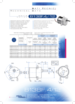
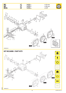
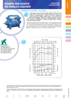
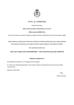
ESECUZIONI SPECIALI ED ACCESSORI
SPECIAL EXECUTION AND ACCESSORIES
RAPPORTI DI RIDUZIONE SPECIALI
SPECIAL REDUCTION RATIOS
Qualora per esigenze particolari, non sia possibile utilizzare i rapporti
di riduzione nominali, elencati nel CAPITOLO 2 CARATTERISTICHE COSTRUTTIVE, è possibile a richiesta costruire rapporti di riduzione nominali iN :
Should it be impossible for specific reasons to use the reduction ratios listed in CHAPTER 2 TECHNICAL INFORMATION, on request the following
reduction ratios iN :
6.3-12.5-28
6.3-12.5-28
Tali rapporti nominali non sono possibili su tutte le grandezze, inoltre,
possono variare da grandezza a grandezza.
The actual ratios may differ enough from the nominal ones, depending
on sizes.
SUPPORTO MOTORE
MOTOR MOUNT
Il supporto motore permette di ottenere un insieme motore elettrico-riduttore estremamente compatto. Tutti i riduttori possono essere
forniti del supporto motore, ad ogni grandezza corrisponde un supporto motore. La tensione della cinghia viene regolata semplicemente
registrando il braccio di reazione del supporto motore. Si raccomandano le seguenti grandezze motore massime.
The motor mount offers a compact solution for electric motor-gear reducer assembly. All reducers can be supplied with a motor mount to suit the
most popular combination. The belt tension is adjusted simply by calibrating the motor mount torque arm. The recommended maximum motor
sizes are the following.
Dimensioni supporto motore
Motor mount dimensions
A
B
C
D
E
F
G
Peso supporto
motore
Kg
Motor mount
weight
208
8
3
200
43
210
81.4
3.4
112 M
132 M - L
160 M
246
287
338
8
3
230
52
235
91.9
4.2
3
290
61
270
105.1
7.6
3
350
66
325
131.8
13.3
380
412
488
3
395
76
340
142.2
17.7
395
80.5
405
161.9
20.6
3
475
103.5
470
189.9
32
250
225 M
545
14
16
16
3
210
180 M
180 M
200 L
10
12
14
3
505
116
555
228.6
41.7
Grandezza motore
Grandezza massima
B3
Size
Maximum motor
size
85
105
125
150
165
180
90 L
Descrizione aggiuntiva alla designazione, esempio:
Further description of designation, example:
RP2C150-19.5 ARO CON TENDITORE CON STAFFE CON SUPPORTO
MOTORE
RP2CC150-19.5 ARO WITH TORQUE ARM WITH BRACKETS AND MOTOR
MOUNT
20
UNITA’ DI BLOCCAGGIO
SHRINK DISC
E’ un dispositivo che permette il montaggio e il fissaggio dell’albero della macchina azionata al riduttore, con l’eliminazione
della linguetta e della rondella di installazione. Il serraggio delle viti genera delle
forze che permettono la trasmissione di
forti momenti torcenti. A richiesta questa
esecuzione può essere fornita sia all’entrata che all’uscita, del dispositivo di tenuta
supplementare, per una più efficace protezione contro le impurità.
E’ necessario un albero cavo speciale
delle dimensioni indicate nella tabella.
The shrink disc is a keyless device for mounting and fixing the machine shaft to the reducer, assuring a perfect control of the transmitting torque.
See the main dimensions of the special
hollow shaft of the table below.
Grandezza
Size
B C
M
Unità di bloccaggio / Shrink disc
D
L
N
A
85
Ø 40H7
153
64
62
27
4
M 6 Ø 50h8
70 Ø 90 22 d 50
12
1.160
58.000
0,8
105
Ø 45H7
176
74
72
30
4
M 6 Ø 55h8
75 Ø100 23 d 55
12
1.520
67.600
1,1
125
Ø 55H7
199
86
83
30
4
M 6 Ø 68h8
86 Ø115 23 d 68
12
2.500
91.000
1,4
150
Ø 60H7
217
95
92
30
4
M 6 Ø 68h8
86 Ø115 23 d 68
12
3.150
105.000
1,4
165
Ø 70H7
238 104,5
101,5
32
5,5
M 8 Ø 80h8 100 Ø145 25 d 80
30
4.600
131.500
1,9
180
Ø 70H7 250
111
107
32
5,5
M 8 Ø 80h8 100 Ø145 25 d 80
30
4.600
131.500
1,9
210
Ø 85H7 311
132,5
128,5
50
7
M10 Ø110h8 136 Ø185 39 d110
59
10.800
254.100
5,9
250
Ø100H7 357
151
146
60
8
M12 Ø140h8 175 Ø230 46 d140
100
17.600
352.000
Viti
Screws
E
F
G
H Tipo
Coppia serraggio viti
Momento trasmissibile
Forza assiale
Peso
Nm
N
Kg
Type Screws tightening torque Nm Transmissible torque
Axial force
Weight
10
MONTAGGIO
Pulire accuratamente le superfici di contatto dell’albero cavo, dell’unità di bloccaggio e dell’albero da serrare. Applicare sugli stessi una
leggera pellicola di lubrificante antiossidazione da contatto.
ATTENZIONE: non usare bisolfuro di molibdeno o altri grassi, causa la
notevole riduzione del coefficiente di attrito. Accertarsi che i dischi siano allineati in piani paralleli. Serrare le viti in modo graduale ed uniforme, secondo uno schema a croce, sino a raggiungere la coppia di
serraggio indicata in tabella. Per raggiungere questo valore, sono necessari più serraggi delle viti.
INSTALLATION
Carefully clean the contact surfaces of the hollow shaft, the locking assembly and the input shaft. These should also be given a light coating of
anti-rust contact lubricant.
WARNING: do not use molybdenum bisulphide or other greases, these
cause a considerable reduction in the friction coefficient.
Ensure that the disks are aligned on parallel planes. Tighten the screws
gradually and evenly in a cross pattern until the screw couple is reached as
indicated in the table. To reach this figure the screws have to be tightened
a number of times.
SMONTAGGIO
Allentare tutte le viti di serraggio con sequenza continua e graduale.
Non estrarre completamente le viti dalle filettature. Normalmente con
queste operazioni l’unità di bloccaggio è sbloccata.
Togliere eventuali ossidazioni formatesi sull’albero cavo e sull’albero
da serrare.
DEMOUNTING
Loosen all the fixing screws in a constant and gradual sequence. Do not
remove them completely from the threads.
Normally this procedure releases the locking assembly. Remove incidental
rust on the hollow shaft and the input shaft.
Descrizione aggiuntiva alla designazione, esempio:
Further description of designation, example:
RP2C150-19.5 ARO SD PREDISPOSTO PER UNITA’ DI BLOCCAGGIO
CON TENDITORE CON STAFFE
RP2C150-19.5 ARO SD SUITABLE FOR SHRINK DISC WITH TORQUE ARM
WITH BRACKETS
21
TENUTA SUPPLEMENTARE
SPECIAL SEALS
Quando il riduttore è installato in ambienti con impurità (polveri, prodotti aggressivi, spruzzi), queste nel funzionamento possono penetrare tra l’anello di tenuta e la sede rotante causando, nel tempo, la
fuoriuscita di olio. E’ possibile fornire il riduttore di una tenuta supplementare, composta da un anello di tenuta frontale ruotante con l’albero in contatto con una superficie fissa.
E’ necessario un albero cavo speciale delle dimensioni indicate
nella tabella.
For critical and aggressive environment ( dust, chemical sprays) and wherever a regular maintenance of sealing rings is impossible, oil leakage
could occur. An additional seal can be supplied with the reducer, namely
rotary front seal rings rotating with the shaft and in contact with a fixed
surface.
A special hollow shaft is necessary for this seal, see the table for size
indications.
D
Grandezza
Size
22
L
N
A
B
C
Anello di tenuta frontale con
dischetto di contatto
Frontseal V-ring with wear plate
Entrata
Input
85
105
125
Ø
Ø
Ø
150
165
180
210
250
Ø 60
Ø 70
Ø 70
Ø 85
Ø 100
40 H 7
45 H 7
55 H 7
H
H
H
H
H
7
7
7
7
7
128
148
172
64
74
86
----55
65
190
209
222
265
302
95
104.5
111
132.5
151
72.5
85
85
102.5
125
----M 6
M 6
M 8
M 10
M 10
M 12
M 12
N° 1
Uscita
Output
N° 2
----16
16
20
25
30
55
20
25
25
32
32
40
45
45
50
60
85
100
100
120
150
65
75
MONTAGGIO
Pulire, sgrassare la superficie frontale degli anelli di tenuta del riduttore e i dischi di contatto.
Applicare su questa superficie un prodotto a base siliconica tipo:
RHÔNE-POULENC CAF1 RHODORSIL o similari. Posare la parte del dischetto più rugosa sull’anello e tenere premuto per qualche secondo,
l’incollaggio completo avviene dopo qualche ora.
Dopo avere ingrassato abbondantemente la superficie del dischetto
ma non l’albero, applicare l’anello di tenuta frontale, allargandolo e infilandolo sull’albero.
FITTING
Clean and degrease the front surface of the speed reducer’s sealing rings and contact disks. Cover the surface with a silicon based product, like
RHÔNE-POULENC CAF1 RHODORSIL, or similar. Now place the roughest
part of the disk on the ring and press down for a few seconds, the glue is
fully effective after a few hours.
After abundantly greasing the surface of the disk, but not the shaft, with
water-repellent grease, fit the frontal sealing ring by opening it and sliding
it onto the shaft.
SMONTAGGIO
Sfilare l’anello di tenuta frontale, poi, servendosi di una lama togliere
il dischetto di contatto. Pulire la superficie dell’anello di tenuta utilizzando carta abrasiva. Sostituire il dischetto, l’anello frontale e ripetere
le operazioni come sopra.
DEMOUNTING
Slide off the frontal sealing ring and then use a knife to remove the contact
disk. Clean the surface of the sealing ring using emery paper. Replace the
disk, the frontal ring and repeat the operations described above.
Descrizione aggiuntiva alla designazione, esempio:
Further description of designation, example:
RP2C150-19.5 ARO VS TENUTA SUPPLEMENTARE CON TENDITORE
CON STAFFE
RP2C150-19.5 ARO VS ADDITIONAL SEAL WITH TORQUE ARM WITH
BRACKETS
MOTORE IDRAULICO
HYDRAULIC MOTOR
Tutti i riduttori possono essere predisposti per l’accoppiamento con
motore idraulico tipo DANFOSS, OMP, OMR ed altri. Questa soluzione
conferisce al gruppo un insieme economico, compatto e silenzioso.
All reducers can be delivered to fit a hydraulic motor, type DANFOSS, OMP,
OMR and others. The resulting assembly is economical, compact and
quiet.
23
ALBERO CAVO, DIAMETRO MASSIMO, DIAMETRI SPECIALI
DIVERSI DA CATALOGO
HOLLOW SHAFT, MAXIMUM DIAMETERS, SPECIAL DIAMETERS NOT IN CATALOGUE
Quando è possibile, installare il riduttore su un albero di diametro
equivalente a quello dell’albero cavo di catalogo.
In caso di impossibilità, si possono costruire alberi cavi di diametro diverso.
La tabella indica diversi casi, compreso il diametro massimo che si può
costruire.
Where possible install the reducer on a shaft having the same diameter as
the ones of hollow shaft. If not possible, hollows shaft with special diameters can be supplied. In the table below we show the range of hollow shaft
values available, where:
Grandezza / Size
D
B
A
E
C
85
105
125
150
165
180
210
250
□ = Predisposto per
bussole di riduzione con
linguetta
Ø 30H7
8
33,3 1,3
Ø 31,4
SPEC
SPEC
Ø 35H7
10
38,3 1,6
Ø 37
SPEC
SPEC
Ø 38H7
10
41,3 1,6
Ø 40
CAT
SPEC
Ø 40H7
12
43,3 1,85
Ø 42,5
MAX
SPEC
SPEC
Ø 45H7
14
48,3 1,85
Ø 47,5
CAT MAX
SPEC
Ø 50H7
14
53,3 2,15
Ø 53
SPEC
SPEC
Ø 55H7
16
59,3 2,15
Ø 58
CAT MAX
SPEC
Ø 60H7
18
64,4 2,15
Ø 63
CAT
SPEC
SPEC
Ø 65H7
18
69,4 2,65
Ø 68
MAX
SPEC
SPEC
Ø 70H7
20
74,9 2,65
Ø 73
CAT
CAT
Ø 75H7
20
79,9 2,65
Ø 78
MAX
MAX
Ø 80H7
22
85,4 2,65
Ø 83,5
Ø 85H7
22
90,4 3,15
Ø 88,5
CAT
Ø 90H7
25
95,4 3,15
Ø 93,5
MAX
Ø100H7 28 106,4 3,15
Ø 103,5
CAT
Ø 114
MAX
Ø110H7 28 116,4 4,15
CAT = Catalogo
SPEC = Speciale
MAX = Massimo
CAT = Standard dimension
SPEC = Special dimension
MAX = Maximum allowable
bore
= Predisposed for
reduction bush with key
□
SPEC
SPEC
SPEC
Descrizione aggiuntiva alla designazione, esempio:
Further description of designation, example:
RP2C150-19.5 ARO D 50 ALBERO CAVO D 50 CON TENDITORE CON
STAFFE
RP2C150-19.5 ARO D 50 HOLLOW SHAFT D 50 WITH TORQUE ARM WITH
BRACKETS
Oltre ai valori di tabella, si possono costruire alberi cavi con misure in
pollici, purchè non superino il diametro massimo possibile.
Hollow shafts can also be made to imperial or American specifications, as
long as they do not exceed the maximum bore size.
24
ALBERO CAVO CON FORI FILETTATI
HOLLOW SHAFTS WITH TAPPED HOLES
La installazione del riduttore sull’albero della macchina da azionare si
può anche ottenere costruendo una particolare rondella, fissata per
mezzo di 4 viti all’albero cavo e dotata di un foro filettato al centro di
diametro superiore al diametro del foro filettato dell’albero della macchina. Questa soluzione permette il montaggio, il fissaggio e lo smontaggio del riduttore.
A richiesta si possono fornire i riduttori con 4 fori filettati sull’albero
cavo, aventi le dimensioni descritte nella tabella.(In alcuni casi, a parità
di grandezza, per gli alberi cavi di foro massimo, i fori filettati possono
essere di diametro inferiore ad un interasse di diametro superiore ).
A richiesta è anche possibile la fornitura della speciale rondella necessaria allo scopo.
The reducer can be easily mounted to, locked to and dismantled from the
input shaft of the driven machine by using a special mounting plate with 4
screws on the same pcd of the threaded holes on hollow shaft and having
a central drilled and tapped hole, the diameter of which is greater than
that of the threaded hole of the driven machine shaft.
Reducers should be then equipped with these 4 threaded holes on the hollow shaft as specified in the table. (In some cases, when the unit is supplied
with the maximum bore, the threaded holes can be smaller than expected
for the hollow shaft, due to a limit thickness of the same). The special washer for this applications can be supplied on request.
Grandezza
Size
D
A
B
C
85
Ø
Ø
Ø
Ø
Ø
25 H 7
30 H 7
35 H 7
38 H 7
40 H 7
46,5
46,5
46,5
46,5
M
M
M
M
6
6
6
6
16
16
16
16
105
Ø
Ø
Ø
Ø
35 H 7
38 H 7
40 H 7
45 H 7
55
55
55
55
M
M
M
M
6
6
6
6
16
16
16
16
125
Ø
Ø
Ø
Ø
40 H 7
45 H 7
50 H 7
55 H 7
65
65
65
65
M
M
M
M
6
6
6
6
16
16
16
16
150
Ø
Ø
Ø
Ø
50 H 7
55 H 7
60 H 7
65 H 7
72,5
72,5
72,5
75
M
M
M
M
8
8
8
6
20
20
20
16
165
Ø
Ø
Ø
Ø
60 H 7
65 H 7
70 H 7
75 H 7
85
85
85
87,5
M 10
M 10
M 10
M 8
25
25
25
20
180
Ø
Ø
Ø
Ø
60 H 7
65 H 7
70 H 7
75 H 7
85
85
85
87,5
M 10
M 10
M 10
M 8
25
25
25
20
210
Ø
Ø
Ø
Ø
Ø
70 H 7
75 H 7
80 H 7
85 H 7
90 H 7
102,5
102,5
102,5
102,5
105
M 12
M 12
M 12
M 12
M 8
32
32
32
32
20
250
Ø 85 H 7
Ø 90 H 7
Ø 100 H 7
Ø 110 H 7
125
125
125
130
M 12
M 12
M 12
M 10
32
32
32
25
Descrizione aggiuntiva alla designazione, esempio:
Further description of designation, example:
RP2C150-19.5 ARO ACF ALBERO CAVO CON FORI CON TENDITORE
CON STAFFE
RP2C150-19.5 ARO ACF HOLLOW SHAFT TAPPED HOLES WITH TORQUE
ARM WITH BRACKETS
25
BUSSOLA DI RIDUZIONE CON LINGUETTA
REDUCTION BUSHING WITH KEY
Questo accessorio permette al cliente di ottenere un riduttore con albero cavo in uscita di diametro inferiore disponendo a magazzino di
un riduttore con albero cavo normale, speciale o massimo, secondo
i casi. Si evita così l’ordinazione di un nuovo gruppo speciale, richiedendo semplicemente una bussola di riduzione con relativa linguetta.
This accessory enables both stockist and endusers to stock only reducers
with the maximum bore hollow output shafts. When smaller diameters
bores are required, use the bushing to obtain the correct fit. The advantage: less investment in stock and greater flexibility to meet market demand.
IMPORTANTE: le bussole di riduzione con linguetta sono applicabili quando il riduttore ha in origine i diametri albero
cavo evidenziati nella tabella albero cavo.
ATTENTION: reduction bushings with key are applicable when
the reducer is originally supplied with hollow shafts having
diameters as reported in the hollow shaft table.
E’ consigliato il bloccaggio assiale della bussola per mezzo di distanziali, rondelle di installazione, etc.
Come si può vedere dalla tabella sotto, per tutte le grandezze, la lunghezza delle bussole è inferiore di 5 mm alla lunghezza dell’albero
cavo.
The bushing should be axially locked using spacers, installation washers,
etc. As can be seen in the table below, in all cases the bushing is 5 mm
shorter than the hollow shaft length.
Grandezza / Size
D
85
Ø 35 H 7
105
125
150
165
180
210
250
Ø 45 H 7
Ø 55 H 7
Ø 65 H 7
Ø 75 H 7
Ø 75 H 7
Ø 90 H 7
Ø 110 H 7
A
Ø 25 H 7
Ø 35 H 7
Ø 40 H 7
Ø 40 H 7
Ø 55 H 7
Ø 60 H 7
Ø 70 H 7
Ø 80 H 7
C
B
E
Ø 30 H 7
111
30
91
Ø 40 H 7
131
38
107
Ø 45 H 7
Ø 50 H 7
149
45
123
Ø 55 H 7
Ø 60 H 7
167
52
139
Ø 70 H 7
186
58
156
Ø 70 H 7
197
63
167
Ø 80 H 7
237
75
202
Ø 100 H 7
272
90
234
Ø 50 H 7
Ø 60 H 7
Ø 65 H 7
Ø 75 H 7
Ø 90 H 7
Ø 65 H 7
Designazione, esempio:
Designation, example:
BUSSOLA DI RIDUZIONE CON LINGUETTA 65-50 RP 150
REDUCTION BUSHING WITH KEY 65-50 RP 150
26
FISSAGGIO DEL RIDUTTORE DIVERSO DA CATALOGO
SPECIAL SUPPLY NOT IN CATALOGUE
TENDITORE
TORQUE ARM WITHOUT BRACKETS
Grandezza
Size
A
B
M
W
K
85
290
0
154,3
13
36
105
328
0
177
13
45
125
385
0
216,1
16
53
150
445
0
251,1
16
58
165
498
0
273,1
16
68
180
549
0
303
16
73
210
639
0
351,8
21
92
250
756
94,2
449
21
104
Descrizione aggiuntiva alla designazione, esempio:
Further description of designation, example:
RP2C150-19.5 ARO CON TENDITORE
RP2C150-19.5 ARO WITH TORQUE ARM
SENZA TENDITORE
WITHOUT TORQUE ARM
Descrizione aggiuntiva alla designazione, esempio:
Further description of designation, example:
RP2C150-19.5 ARO
RP2C150-19.5 ARO
27
TENDITORE CON PIASTRA
TORQUE ARM WITH PLATE
Grandezza
Size
A
G
M
Q
W
K
85
297
85
165
14
8
35
105
350
102
200
16
8
44
125
388
115
220
18
10
51
150
454
120
260
20
12
56
165
534
135
315
21
15
66
180
558
155
320
22
15
70
210
657
175
375
25
15
89
250
752
190
450
28
15
101
Descrizione aggiuntiva alla designazione, esempio:
Further description of designation, example:
RP2C150-19.5 ARO CON TENDITORE CON PIASTRA
RP2C150-19.5 ARO WITH TORQUE ARM WITH PLATE
RIDUTTORE CON ALBERO DI ENTRATA BISPORGENTE
SPEED REDUCER WITH DOUBLE EXTENDED INPUT SHAFT
In questa esecuzione speciale non è possibile installare il dispositivo
antiretro.
The backstop device cannot be installed in this execution.
Descrizione aggiuntiva alla designazione, esempio:
Further description of designation, example:
RP2C150-19.5 B BISPORGENTE CON TENDITORE CON STAFFE
RP2C150-19.5 B DOUBLE EXTENDED INPUT SHAFT WITH TORQUE ARM
WITH BRACKETS
RIDUTTORE CON ALBERO DI ENTRATA SPORGENTE DAL
LATO OPPOSTO A QUELLO DI CATALOGO
SPEED REDUCER WITH INPUT SHAFT ON THE OPPOSITE SIDE
In questa esecuzione speciale, nelle grandezze: 85-105-125-150-165
non è possibile installare il dispositivo antiretro.
In this special execution, with sizes: 85-105-125-150-165 the backstop device cannot be fitted.
Descrizione aggiuntiva alla designazione,esempio:
Further description of designation, example:
RP2C150-19.5 O OPPOSTO CON TENDITORE CON STAFFE
RP2C150-19.5 O OPPOSITE WITH TORQUE ARM WITH BRACKETS
TRATTAMENTO ANTIGRIPPANTE E ANTIUSURA ALBERO CAVO
ANTI-FRETTING CORROSION TREATMENT OF HOLLOW SHAFT
Descrizione aggiuntiva alla designazione, esempio:
Further description of designation, example:
RP2C150-19.5 ARO ACFF ALBERO CAVO CON TRATTAMENTO FF
CON TENDITORE CON STAFFE
RP2C150-19.5 ARO ACFF HOLLOW SHAFT WITH TREATMENT FF WITH
TORQUE ARM WITH BRACKETS
28
© Copyright 2026 Paperzz