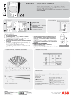
Centralina Elettronica di Controllo
Per gestire due semafori a due luci.
oppure
Per gestire i semafori di un incrocio di due strade con
semafori a due luci.
Manuale di Installazione pag. 2-12
____
Control Unit Board
For traffic Light with two Lights.
or
for controlling four traffic lights with two lights at a four
ways intersection.
Sede Legale
Domotime srl
Via Michelangelo, 152/B 25010 Desenzano d/G (Bs) – Italy
Sede Operativa
Via Monico, 9 25017 Lonato d/G (Bs) - Italy
Tel +39 030 9913901 Fax +39 030 9901307
Skype: domotime
Email [email protected] Web site www.domotime.com
Installation
Manual pag…..13-23
CE
Installation Manual
Manuale di istruzioni
AVVERTENZE PER
L’INSTALLATORE
La messa in servizio e la manutenzione della centralina
devono essere effettuate esclusivamente da installatori
qualificati.
NOTES
Use a 24 voltage for this LED traffic light.
Set the dip after power has been disconnected.
Disconnect the power supply whenever working on the circuit board
or on the traffic light.
Scollegare l’alimentazione elettrica quando si effettuano i
collegamenti.
The traffic lights are designed to remain on red light whenever the
detectors are sending always the same signal to the traffic lights. This
may occur for example when the photocells are blocked or fail for any
reason.
Utilizzare la centralina esclusivamente per la gestione dei
semafori a due luci.
Settare i Dip dopo aver scollegato l’alimentazione.
Proteggere i relè con fusibili del tipo F1 e F2 con portata max
2° sui comuni dei due semafori.
A differential magnetothermic switch before connecting the central
unit power supply is recommended.
Installare un interruttore differenziale magnetotermico prima
di collegare la centralina all’alimentazione.
Si raccomanda l’utilizzo di ricambi originali. L’utilizzo di parti
non originali comporta il decadimento della garanzia e della
responsabilità del produttore per eventuali danni.
2
Domotime srl
Via Michelangelo 152/B – 25010 Desenzano d/G (Bs) - Italy
To prevent from short circuit use two F1 and F2 fuses with adequate
capacity (max 2A) on the two commons of the two traffic lights.
MAINTENANCE
Periodically check the proper functioning of traffic lights as preset by
the installer.
Domotime srl
Via Michelangelo 152/B – 25010 Desenzano d/G (Bs) - Italy
23
Installation Manual
Manuale di istruzioni
PRESENTAZIONE
DEL PRODOTTO
Questa centralina elettronica di controllo per semafori è stata
progettata per il loro collegamento in situazioni nelle quali è richiesta
una gestione organizzata dei passaggi e degli accessi come sensi unici
alternati, crocevia, stazioni di servizio, aree di sosta ecc.
La centralina elettronica può funzionare con o senza l’ausilio di
apparecchi di rilevamento che ne regolano il funzionamento.
Nel primo caso la durata delle fasi di verde e di rosso saranno
regolate da fotocellule collegate alla centralina.
Nel secondo caso basterà agire sui trimmer della centralina per
preimpostare tempi fissi di durata delle fasi di rosso e di verde.
Inoltre,
questa
centralina
può
gestire
4
semafori
contemporaneamente come ad es. in prossimità di incroci stradali
dove è necessario gestire il traffico proveniente da quattro direzioni
diverse.
22
Domotime srl
Via Michelangelo 152/B – 25010 Desenzano d/G (Bs) - Italy
Domotime srl
Via Michelangelo 152/B – 25010 Desenzano d/G (Bs) - Italy
3
Installation Manual
Manuale di istruzioni
OPERATING WITH 4
TRAFFIC LIGHTS
DATI TECNICI
This unit can handle up to 4 traffic lights with two lights. This
way it is possible to coordinate the passage of cars at 4
ways junctions.
Alimentazione 230V 50 Hz (5 VA)
Nr. 1 fusibile per protezione linea 24V ac. 130 mA max.
Nr. 1 fusibile per protezione uscita linea 160 mA
Nr. 1 fusibile per protezione uscita ausiliaria 160 mA
Nr. 4 uscite a relè con contatto pulito in commutazione (230V 2A max)
Nr. 2 ingressi per dispositivi di controllo settabili N.A. o N.C.
Nr. 1 microinterruttore (Dip 2) per selezione ingressi N.A. e N.C.
Nr. 1 microinterruttore Dip 1 per funzionamento con dispositivo di rilevamento
Nr. 1 Trimmer (T1) per regolazione tempo di luce rossa (range da 5 a 120 secondi)
Nr. 1 Trimmer (T2) per regolazione tempo di luce verde (range da 5 a 120 secondi)
Nr. 1 Trimmer (T3) per regolazione tempo di priorità (range da 5 a 120 secondi)
Nr. 5 LED per segnalazione stato ingressi e uscite
I due microintenrruttori Dip consentono due tipi di funzionamento della
centralina e la possibilità di scegliere il tipo di contatto per i dispositivi di
controllo in ingresso.
DIP 1
OFF
CONFIGURAZIONE PER FUNZIONAMENTO A TEMPI PREIMPOSTATI
DIP 2
OFF
DIP 1
DIP 2
ON
OFF
CONFIGURAZIONE PER FUNZIONAMENTO CON L’AUSILIO DI DISPOSITIVI DI
RILEVAMENTO TIPO N.A.
DIP 1
DIP 2
ON
OFF
CONFIGURAZIONE PER FUNZIONAMENTO CON L’AUSILIO DI DISPOSITIVI DI
RILEVAMENTO TIPO N.C.
WIRING 4 TRAFFIC
LIGHTS WITH TWO
LIGHTS TO THE CENTRAL
BOARD
In this case it is necessary to connect the two equal colors of
the opposed traffic lights on the same central board output
(V1-R1-V2-R2). The returning wire of each traffic light is a
common which is connected to the neutral for the power
supply.
4
Domotime srl
Via Michelangelo 152/B – 25010 Desenzano d/G (Bs) - Italy
Domotime srl
Via Michelangelo 152/B – 25010 Desenzano d/G (Bs) - Italy
21
Installation Manual
DESCRIPTION OF
THE PRESET TIME
OPERATING MODE
This configuration provides that when the unit is turned on
both lights are on red. The duration of this phase is preset
by the installer on trimmer T1. After the preset time the unit
will turn green the light connected to terminal 1 and keep
the light connected to terminal 2 on red. Even for this phase
the duration will be preset by the installer, but this time by
acting T2 trimmer.
At this stage both lights come back on red for the duration
preset by T1.
Now the unit will turn on the lights again but this time it will
reverse the connections, making red the light connected to
terminal 1 and green the light connected to terminal 2. Once
again, the duration of this phase is the default on T2.
Finally the two lights come back again on red and the cycle
repeats.
Manuale di istruzioni
DESCRIZIONE DEL FUNZIONAMENTO CON L’AUSILIO DI DISPOSITIVI DI
RILEVAMETO
1
2
3
4
5
6
7
Quando si accende la centralina elettronica ambedue i semafori si posizionano sul
rosso per il tempo preimpostato dall’installatore sul Trimmer 1
scaduto il tempo del Trimmer 1 il semaforo del rilevatore sollecitato da un
passaggio diventa verde per il tempo preimpostato dal Trimmer 2 mentre l’altro
semaforo rimane sul rosso. Il tempo del Trimmer 1 viene azzerato ad ogni
successivo passaggio. L’azzeramento si arresta solo quando anche l’altro
rilevatore viene attivato
Quando anche la fotocellula o il rilevatore posti sull’altro semaforo vengono
eccitate parte il tempo preimpostato sul Trimmer 3
Finito il tempo sul Trimmer 3, l’azzeramento continuo del Trimmer2 viene
bloccato
Quando anche il tempo del Trimmer 2 si esaurisce entrambi e semafori tornano
sul rosso.
I semafori restano sul rosso per il tempo impostato su Trimmer 1
Scaduto il tempo del Trimmer 1 il ciclo si ripete con il verde del semaforo che
inizialmente era rimasto sul rosso
NOTE IMPORTANTI
I semafori sono progettati per rimanere sul rosso nei casi in cui i rilevatori dovessero inviare
sempre lo stesso segnale al semaforo. Ciò può avvenire ad esempio quando le fotocellule si
bloccano o si guastano per un qualsiasi motivo.
Settare i Dip solo dopo aver scollegato l’alimentazione.
20
Domotime srl
Via Michelangelo 152/B – 25010 Desenzano d/G (Bs) - Italy
Domotime srl
Via Michelangelo 152/B – 25010 Desenzano d/G (Bs) - Italy
5
Installation Manual
Manuale di istruzioni
CONFIGURAZIONE DEL
FUNZIONAMENTO CON
L’AUSILIO DI
DISPOSITIVI DI
RILEVAMENTO
Per configurare il funzionamento della centralina con
l’ausilio di dispositivi di rilevamento (es. fotocellule)
agire come indicato di seguito:
-
-
-
6
Posizionare Dip 1 su ON;
Posizionare Dip 2 in posizione OFF per contatti
NA ovvero in posizione ON per contatti NC;
Regolare il Trimmer T1 per impostare la durata
della fase durante la quale i semafori devono
essere ambedue rossi. E’ possibile impostare un
tempo che va da un minimo di 5 secondi ad un
massimo di 120.
Regolare il trimmer T2 per impostare la durata
della fase durante la quale uno dei semafori
deve essere verde (min. 5 sec. Max 120).
Per evitare il reset ripetuto del trimmer T2
dovuto a ripetuti passaggi davanti al dispositivo
di rilevamento, regolare il Trimmer T3 (min. 5
sec. Max 120)
Domotime srl
Via Michelangelo 152/B – 25010 Desenzano d/G (Bs) - Italy
CONFIGURING THE
PRESET TIME
OPERATING MODE
To configure the operation with a predetermined duration of the
phases of green and red act as follows:
-
-
-
Position Dip 1 OFF;
Adjust trimmer T1 to set the duration of the phase
during which the two lights must be on red. You can
set a time ranging from a minimum of 5 seconds to a
maximum of 120;
Adjust the trimmer T2 to set the duration of the
phase during which the two lights must be on green
(between 5 and 120 sec.);
The Trimmer T3 should not be changed.
Domotime srl
Via Michelangelo 152/B – 25010 Desenzano d/G (Bs) - Italy
19
Installation Manual
CONFIGURING THE
BOARD WITH
DETECTION
DEVICES
To configure the central board for the use with detection
devices (eg photocells) act as follows:
-
-
-
18
set Dip 1 ON;
set DIP 1 in OFF position for NA contacts or in the
ON position for NC contacts;
adjust trimmer T1 to set the duration of the phase
during which the two lights must be red. You can
set a time ranging from a minimum of 5 seconds to
a maximum of 120.
adjust the trimmer T2 to set the duration of the
phase during which red light must be green (at least
5 sec. Max 120 sec.);
to avoid the repeated resetting of the trimmer T2
due to repeated passages in front of the detection
device, adjust the trimmer T3 (min. 5 sec. Max 120)
Domotime srl
Via Michelangelo 152/B – 25010 Desenzano d/G (Bs) - Italy
Manuale di istruzioni
DESCRIZIONE DEL
FUNZIONAMENTO A
TEMPI PREIMPOSTATI
La configurazione per il funzionamento a tempi predeterminati
prevede che quando la centralina viene accesa ambedue i
semafori si trovino sul rosso. La durata di questa fase è quella
preimpostata dall’installatore sul trimmer T1. Trascorso il
tempo predeterminato la centralina farà diventare verde il
semaforo collegato al morsetto 1 mentre manterrà sul rosso il
semaforo collegato al morsetto 2. Anche per questa fase la
durata sarà preimpostata dall’installatore ma questa volta
agendo trimmer T2.
A questo punto entrambi i semafori tornano sul rosso per la
durata preimpostata con T1.
Infine la centralina provvederà ad accendere i semafori uno
rosso e l’altro verde ma questa volta invertendo i collegamenti,
facendo diventare rosso il semaforo collegato al morsetto 1 e
verde quello collegato al morsetto 2. Ancora una volta la
durata di questa fase è quella preimpostata su T2.
I semafori tornano poi ambedue sul rosso e il ciclo si ripete.
Domotime srl
Via Michelangelo 152/B – 25010 Desenzano d/G (Bs) - Italy
7
Installation Manual
Manuale di istruzioni
CONFIGURAZIONE
DEL
FUNZIONAMENTO A
TEMPI
PRE IMPOSTATI
Per configurare il funzionamento con durata predeterminata
delle fasi di verde e di rosso agire come indicato di seguito:
-
-
posizionare Dip 1 e Dlp 2 su OFF;
regolare il Trimmer T1 per impostare la durata della
fase durante la quale i semafori devono essere
ambedue rossi. E’ possibile impostare un tempo che va
da un minimo di 5 secondi ad un massimo di 120.
regolare il trimmer T2 per impostare la durata della
fase durante la quale i semafori devono essere
ambedue verdi (min. 5 sec. Max 120).
Il Trimmer T3 non va modificato
DESCRIPTION OF OPERATING WITH DETECTION DEVICES
1
2
3
4
5
6
7
Turning on the electronic control unit both traffic lights are positioned on the red
for the time preset by the installer on the trimmer 1
When the Trimmer 1 preset time is passed the traffic light connected to the
detection device which has been solicited turns green for the time preset by
Trimmer 2 while the other remains on red.
The preset time is reset by each successive passage. The reset is stopped only
when the other detector is triggered.
When even the photocell or the detector placed on the other traffic light is excited
starts the Trimmer 3 preset time
When the preset time of Trimmer 3 is finished, the continuos reset of Trimmer 2
is locked.
When even the time of the trimmer 2 is exhausted both traffic lights come back
on red.
The traffic light remain on red light during the preset time of Trimmer 1
When preset time of Trimmer 1 has expired cycle repeats with the green traffic
light that was initially left on red
NOTES
The traffic lights are designed to remain on red in cases where the detectors should always
send the same signal at the traffic lights. This may occur for example when the photocells are
blocked or fail for any reason.
Set the dip only after disconnecting the power
8
Domotime srl
Via Michelangelo 152/B – 25010 Desenzano d/G (Bs) - Italy
Domotime srl
Via Michelangelo 152/B – 25010 Desenzano d/G (Bs) - Italy
17
Installation Manual
TECHNICAL DATA
Power supply 230V 50 Hz (5 VA)
No. 1 24V ac Auxiliary output max 130 mA
No. 1 160 mA protection fuse
No. 1 160 mA protection fuse for auxiliary output
No. 4 relay outputs with clean contact switch (230V 2A max)
No. 2 inputs for settable control devices N.O. or N.C
No. 1 Dip 2 switch input selection for NA and N.C.
No. 1 Dip 1 switch for use with detection devices
No. 1 Trimmer (T1) for time adjustment of red light (interval from 5 to 120
seconds)
No. 1 Trimmer (T2) for time adjustment of green light (interval from 5 to 120
seconds)
No. 1 Trimmer (T3) for time adjustment of priorities (range 5 to 120 seconds)
No. 5 LED to indicate status of inputs and outputs
The two DIP switches allow to choose between two types of instrument
operation and also to choose the type of contact for incoming control
devices.
DIP 1 OFF
CONFIGURATION FOR A PRESET TIME OPERATION
DIP 2 OFF
DIP 1
ON
DIP 2
OFF
DIP 1
ON
Manuale di istruzioni
FUNZIONAMENTO
CON 4 SEMAFORI A 2
LUCI
Questa centralina può gestire anche 4 semafori a due luci. In
questo modo è possibile coordinare il passaggio delle automobli
in prossimità di incroci.
SCHEMA DI
COLLEGAMENTO DI 4
SEMAFORI ALLA
CENTRALINA PER
SINCRONIZZARE UN
INCROCIO A 4
STRADE
CONFIGURATION FOR OPERATING WITH THE AID OF DETECTION
DEVICE TYPE NO
CONFIGURATION FOR OPERATING WITH THE AID OF DETECTION
DEVICE TYPE N.C.
In questo caso è necessario collegare sulla stessa uscita della
centralina (V1-R1-V2-R2) i due colori uguali dei semafori
contrapposti, il filo di ritorno di ogni semaforo è un comune che
va collegato al neutro per l’alimentazione.
16
Domotime srl
Via Michelangelo 152/B – 25010 Desenzano d/G (Bs) - Italy
Domotime srl
Via Michelangelo 152/B – 25010 Desenzano d/G (Bs) - Italy
9
Installation Manual
Manuale di istruzioni
PRODUCT OVERVIEW
This electronic control unit for traffic lights has been designed to
link two traffic lights together in situations demanding an
organized management of entrances and passages as
alternating one-way streets, crossroads, service stations, rest
areas etc.
The electronic control unit can operate with or without the aid of
detection equipment that regulate the operation.
In the first case the duration of the phases of green and red will
be regulated by photocells or other detecting devices connected
to the control unit.
In the second case, you just adjust the trimmer unit for
presetting a fixed time duration of the phases of red and green.
This unit can handle up to 4 traffic lights with two lights eg. for
coordinating the passage of cars at 4 ways junctions.
10
Domotime srl
Via Michelangelo 152/B – 25010 Desenzano d/G (Bs) - Italy
Domotime srl
Via Michelangelo 152/B – 25010 Desenzano d/G (Bs) - Italy
15
Installation Manual
IMPORTANT
Installation and maintenance must be performed by qualified
personnel.
Manuale di istruzioni
MANUTENZIONE
Scollegare l’alimentazione elettrica ogni volta che si interviene
sulla scheda elettronica o sul semaforo.
Disconnect the power supply when while connecting the
cables
Use the central unit board for traffic light with 2 lights only.
Verificare periodicamente il regolare funzionamento del semaforo
secondo quanto preimpostato dall’installatore sulla scheda
elettronica.
We recommend the use of original spare parts. The use of
other replacement parts will void the manufacturer's warranty
and responsability for any damage.
14
Domotime srl
Via Michelangelo 152/B – 25010 Desenzano d/G (Bs) - Italy
Domotime srl
Via Michelangelo 152/B – 25010 Desenzano d/G (Bs) - Italy
11
Installation Manual
Headquarter
Domotime srl
Via Michelangelo, 152/B 25010 Desenzano d/G (Bs) – Italy
Warehouse and Offices
Via Monico, 9 25017 Lonato d/G (Bs) - Italy
Tel +39 030 9913901 Fax +39 030 9901307
Skype: domotime
Email [email protected] Web site www.domotime.com
12
13
© Copyright 2026 Paperzz