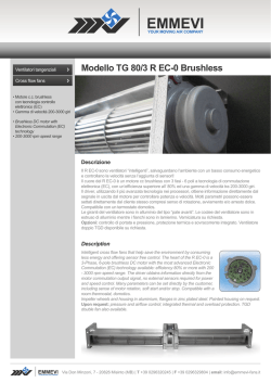
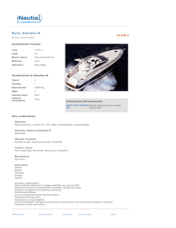
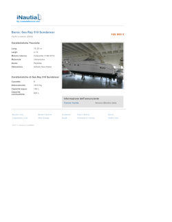
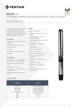
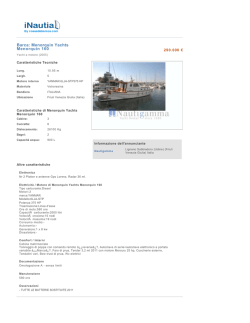
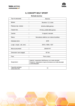
EC
Modello EC1- EC2 - EC3
Model EC1- EC2 - EC3
• Motore A.C. Forma B14 - CE
• Riduttore epicicloidale
• Stelo filettato trapezoidale o a ricircolo di sfere (VRS)
• Asta traslante in acciaio cromato
• Lubrificazione a grasso
• IP 50 / IP 65
• Temperatura di funzionamento -10°C +60°C
• Impiego intermittente S3 30% (5 min) a 30°C*
• Fine corsa integrato di serie
• Potenziometro ed encoder a richiesta
• Dispositivo di antirotazione di serie
(*) Per impieghi diversi contattare il Ns Ufficio Tecnico
• A.C. motor, flange B14 - CE
• Planetary gearbox
• Acme lead screw or ballscrew (VRS)
• Chrome plated steel push rod
• Grease Lubricated
• IP 50 / IP 65
• Working temperature range -10°C +60°C
• Intermittent duty S3 30% (5 min) a 30°C*
• Integrated Limit switches for standard
• Potentiometer and encoder on request
• Antirotation device
(*) For any special duty please contact our technical dept.
EC1 (Vac)
Fmax
Fmax
(N)
500
1250
2000
5000
5000
5000
Rapporti Riduzione
Velocità Versione Taglia motore Potenza motore Giri motore
Motor size
Motor power Motor speed Gearbox Reduction Ratio
Speed Version
(mm/s)
(KW)
(rpm)
193
M01
IEC63
0.37
2800
1/1
97
M02
IEC71
0.37
1400
1/1
60
M03
IEC71
0.37
900
1/1
24
M04
IEC71
0.55
1400
1/4
15
M05
IEC71
0.25
900
1/4
6
M06
IEC63
0.13
1400
1/16
Fmax
Fmax
(N)
500
1250
2000
5000
5000
5000
Rapporti Riduzione
Velocità Versione Taglia motore Potenza motore Giri motore
Motor size
Motor power Motor speed Gearbox Reduction Ratio
Speed Version
(mm/s)
(KW)
(rpm)
230
M01
IEC63
0.18
2800
1/1
115
M02
IEC63
0.18
1400
1/1
75
M03
IEC71
0.25
900
1/1
30
M04
IEC63
0.18
1400
1/4
19
M05
IEC71
0.18
900
1/4
7
M06
IEC63
0.13
1400
1/16
Fmax
Fmax
(N)
1000
2500
2500
10000
10000
10000
Rapporti Riduzione
Velocità Versione Taglia motore Potenza motore Giri motore
Motor size
Motor power Motor speed Gearbox Reduction Ratio
Speed Version
(mm/s)
(KW)
(rpm)
193
M01
IEC80
0.75
2800
1/1
97
M02
IEC80
0.75
1400
1/1
60
M03
IEC80
0.55
900
1/1
24
M04
IEC80
1.1
1400
1/4
15
M05
IEC80
0.55
900
1/4
6
M06
IEC71
0.25
1400
1/16
Fmax
Fmax
(N)
1250
2500
5000
10000
10000
Rapporti Riduzione
Velocità Versione Taglia motore Potenza motore Giri motore
Motor size
Motor power Motor speed Gearbox Reduction Ratio
Speed Version
(mm/s)
(KW)
(rpm)
230
M01
IEC71
0.37
1400
1/1
150
M02
IEC80
0.55
900
1/1
60
M03
IEC71
0.37
1400
1/4
35
M04
IEC80
0.55
900
1/4
15
M05
IEC63
0.18
1400
1/16
Fmax
Fmax
(N)
2500
5000
5000
15000
15000
15000
Rapporti Riduzione
Velocità Versione Taglia motore Potenza motore Giri motore
Motor size
Motor power Motor speed Gearbox Reduction Ratio
Speed Version
(mm/s)
(KW)
(rpm)
193
M01
IEC90
2.20
2800
1/1
97
M02
IEC90
1.80
1400
1/1
60
M03
IEC90
1.50
900
1/1
24
M04
IEC90
1.80
1400
1/4
15
M05
IEC90
1.10
900
1/4
6
M06
IEC71
0.37
1400
1/16
Fmax
Fmax
(N)
3000
3000
10000
15000
15000
Rapporti Riduzione
Velocità Versione Taglia motore Potenza motore Giri motore
Motor size
Motor power Motor speed Gearbox Reduction Ratio
Speed Version
(mm/s)
(KW)
(rpm)
230
M01
IEC80
0.75
1400
1/1
150
M02
IEC80
0.55
900
1/1
60
M03
IEC80
0.75
1400
1/4
35
M04
IEC80
0.55
900
1/4
15
M05
IEC71
0.25
1400
1/16
D vite
Screw D
(mm)
18
18
18
18
18
18
Passo
Pitch
(mm)
4
4
4
4
4
4
Rendimento
Efficiency
D vite
Screw D
(mm)
16
16
16
16
16
16
Passo
Pitch
(mm)
5
5
5
5
5
5
Rendimento
Efficiency
D vite
Screw D
(mm)
25
25
25
25
25
25
Passo
Pitch
(mm)
4
4
4
4
4
4
Rendimento
Efficiency
D vite
Screw D
(mm)
25
25
25
25
25
Passo
Pitch
(mm)
10
10
10
10
10
Rendimento
Efficiency
D vite
Screw D
(mm)
32
32
32
32
32
32
Passo
Pitch
(mm)
4
4
4
4
4
4
Rendimento
Efficiency
D vite
Screw D
(mm)
32
32
32
32
32
Passo
Pitch
(mm)
10
10
10
10
10
Rendimento
Efficiency
0.34
0.34
0.34
0.32
0.32
0.31
Corsa max (mm)
Max stroke [mm]
EC1-F
EC1
365
365
520
520
650
650
590
590
590
590
590
590
EC1 VRS (ballscrew) (Vac)
0.90
0.90
0.90
0.86
0.86
0.81
Corsa max (mm)
Max stroke [mm]
EC1-VRS-F
EC1-VRS
365
355
500
500
625
625
495
495
495
495
495
495
EC2 (Vac)
0.28
0.28
0.28
0.27
0.27
0.25
Corsa max (mm)
Max stroke [mm]
EC2-F
EC2
450
450
635
635
795
795
945
945
945
945
945
945
EC2 VRS (ballscrew) (Vac)
0.90
0.90
0.86
0.86
0.81
Corsa max (mm)
Max stroke [mm]
EC2-VRS-F
EC2-VRS
630
630
785
785
1225
1225
875
875
875
875
EC3 (Vac)
0.24
0.24
0.24
0.23
0.23
0.22
Corsa max (mm)
Max stroke [mm]
EC3-F
EC3
520
520
735
735
915
915
1205
1370
1205
1370
1205
1370
EC3 VRS (ballscrew) (Vac)
0.90
0.90
0.86
0.86
0.81
Corsa max (mm)
Max stroke [mm]
EC3-VRS-F
EC3-VRS
710
710
885
885
1360
1360
1285
1285
1150
1150
edizione - edition
02/2011
161
EC
EC1 / 2 / 3
g3
112
c3
g1
c2
g2
P
c4
a2
H
a3
a1
a4
Attacco anteriore / Front Ends
Versione A7 / Version A7
Versione / Version
1)
2)
a2
a3
a4
(Øh7)
b1 b2
b3
c1
c2
c3
c4
g1
g2
g3
1
133 103
*
61
Ø14 105 145 M10 Ø30 Ø65
41
50
103
*
2
191 156
*
66
Ø20 140 200 M12 Ø45 Ø85
68
65
118
*
3
245 200
*
75
Ø30 190 270 M18 Ø60 Ø105 94
80
138
*
TABELLA DIMENSIONI VRS / BALLSCREW DIMENSIONS TABLE
GR. / SIZE
1
1)
1)
2)
a1
a2
a3
a4
*
61
146 116
(Øh7)
b1 b2
2)
c4
g1
g2
g3
Ø14 105 145 M10 Ø30 Ø65
41
50
103
*
b3
c1
c2
c3
EC1-VRS
1)
a1
2)
EC1
TABELLA DIMENSIONI STANDARD / DIMENSIONS TABLE
GR. / SIZE
b3
Ø
b2
c1
95
b1
M01 M02 M03 M04 M05 M06
a3
147 157 157 157 157 172
g3
131 141 141 141 141 156
Versione / Version
M01 M02 M03 M04 M05 M06
a3
147 147 157 147 157 172
g3
131 131 141 131 141 156
257 222
*
66
Ø20 140 200 M12 Ø45 Ø85
68
65
118
*
Versione / Version
307 262
*
75
Ø30 190 270 M18 Ø60 Ø105 94
80
138
*
M01 M02 M03 M04 M05 M06
1) Dimensions are valid for
stroke = 0, for the exact overall
dimension add the wanted
stroke in mm.
2) Dimensions change according to actuator model.
See charts sidewards.
EC2-VRS
1) Le quote valgono per
corsa = 0, per l'esatto ingombro aggiungere la corsa
desiderata in mm.
2) Quote che variano in base
alla versione dell’attuatore.
Vedere tabelle a lato.
EC2
2
3
a3
182 182 182 182 182 201
g3
158 158 158 158 158 177
Versione / Version
M01 M02 M03 M04 M05
a3
169 182 169 182 201
g3
145 158 145 158 177
DIMENSIONI MOTORI C.A. / A.C. MOTORS DIMENSIONS
71
80
90
162
edizione - edition
02/2011
H
Standard
185
Autofrenante / Brake motors
234
Standard
215
Autofrenante / Brake motors
267
Standard
238
Autofrenante / Brake motors
296
Standard
255
Autofrenante / Brake motors
319
Ø
P
123
110
140
121
159
138
Versione / Version
176
149
EC3
63
VERSIONE / TYPE
EC3-VRS
GR. / SIZE
M01 M02 M03 M04 M05 M06
a3
200 200 200 200 200 226
g3
173 173 173 173 173 199
Versione / Version
M01 M02 M03 M04 M05
a3
188 188 188 188 226
g3
161 161 161 161 199
EC
Modello EC4 - EC5
Model EC4 - EC5
• Motore A.C. Forma B14 - CE
• Riduttore epicicloidale
• Stelo filettato trapezoidale o a ricircolo di sfere (VRS)
• Asta traslante in acciaio cromato
• Lubrificazione a grasso
• IP 50 / IP 65
• Temperatura di funzionamento -10°C +60°C
• Impiego intermittente S3 30% (5 min) a 30°C*
• Fine corsa,potenziometro ed encoder a richiesta
• A.C. motor, flange B14 - CE
• Planetary gearbox
• Acme lead screw or ballscrew (VRS)
• Chrome plated steel push rod
• Grease Lubricated
• IP 50 / IP 65
• Working temperature range -10°C +60°C
• Intermittent duty S3 30% (5 min) a 30°C*
• Limit switches,potentiometer and encoder on request
(*) Per impieghi diversi contattare il Ns Ufficio Tecnico
(*) For any special duty please contact our technical dept.
EC4 (Vac)
Fmax
Fmax
(N)
15000
25000
30000
30000
Rapporti Riduzione
Velocità Versione Taglia motore Potenza motore Giri motore
Motor size
Motor power Motor speed Gearbox Reduction Ratio
Speed Version
(mm/s)
(KW)
(rpm)
56
M01
IEC112
2.20
900
1/4
42
M02
IEC100
4.00
1400
1/4
25
M03
IEC112
3.00
900
1/4
10
M04
IEC90
1.50
1400
1/16
Fmax
Fmax
(N)
25000
30000
30000
Rapporti Riduzione
Velocità Versione Taglia motore Potenza motore Giri motore
Motor size
Motor power Motor speed Gearbox Reduction Ratio
Speed Version
(mm/s)
(KW)
(rpm)
60
M01
IEC90
1.80
1400
1/4
35
M02
IEC100
1.50
900
1/4
15
M03
IEC90
1.10
1400
1/16
Fmax
Fmax
(N)
50000
50000
Rapporti Riduzione
Velocità Versione Taglia motore Potenza motore Giri motore
Motor size
Motor power Motor speed Gearbox Reduction Ratio
Speed Version
(mm/s)
(KW)
(rpm)
11
M01
IEC100
3.00
1400
1/16
7
M02
IEC100
2.20
900
1/16
Fmax
Fmax
(N)
50000
50000
Rapporti Riduzione
Velocità Versione Taglia motore Potenza motore Giri motore
Motor size
Motor power Motor speed Gearbox Reduction Ratio
Speed Version
(mm/s)
(KW)
(rpm)
15
M01
IEC90
1.10
1400
1/16
10
M02
IEC90
0.75
900
1/16
D vite
Screw D
(mm)
40
40
40
40
Passo
Pitch
(mm)
14
7
7
7
Rendimento
Efficiency
D vite
Screw D
(mm)
40
40
40
Passo
Pitch
(mm)
10
10
10
Rendimento
Efficiency
D vite
Screw D
(mm)
55
55
Passo
Pitch
(mm)
9
9
Rendimento
Efficiency
D vite
Screw D
(mm)
50
50
Passo
Pitch
(mm)
10
10
Rendimento
Efficiency
0.36
0.27
0.27
0.25
Corsa max (mm)
Max stroke [mm]
EC4-F
EC4
1545
1545
1405
1475
1345
1345
1345
1345
EC4 VRS (ballscrew) (Vac)
0.86
0.86
0.81
Corsa max (mm)
Max stroke [mm]
EC4-VRS-F
EC4-VRS
1535
1535
1400
1400
1400
1400
EC5 (Vac)
0.23
0.23
Corsa max (mm)
Max stroke [mm]
EC5-F
EC5
1810
1820
1810
1820
EC5 VRS (ballscrew) (Vac)
0.81
0.81
Corsa max (mm)
Max stroke [mm]
EC5-VRS-F
EC5-VRS
1820
1820
1820
1820
edizione - edition
02/2011
163
EC
EC4 / 5
g3
112
c3
g1
c2
g2
P
c4
a2
H
a3
a1
a4
Attacco anteriore / Front ends
Versione A7 / Version A7
b2
Ø
Versione / Version
1)
2)
a1
a2
a3
a4
**
*
79.5 40
79.5 40
4
269 214
5
269 214
Øh7
b1 b2
2)
c3
c4
g1
g2
g3
200 300 M24x2 70
105
70
80
136
200 300 M24x2 70
105
70
80
1 36
**
*
b3
c1
c2
TABELLA DIMENSIONI VRS / BALLSCREW DIMENSIONS TABLE
GR. / SIZE
1)
1)
2)
a1
a2
a3
a4
**
*
79.5 40
79.5 40
4
316 261
5
316 261
Øh7
b1 b2
2)
c3
c4
g1
g2
g3
200 300 M24x2 70
105
70
80
136
200 300 M24x2 70
105
70
80
13 6
**
*
b3
c1
c2
M01
a3
g3
EC4-VRS
GR. / SIZE
1)
EC4
TABELLA DIMENSIONI STANDARD / DIMENSIONS TABLE
M02
M03
218
218
218
Versione / Version
M01
a3
g3
DIMENSIONI MOTORI C.A. / A.C. MOTORS DIMENSIONS
GR. / SIZE
VERSIONE / TYPE
H
Standard
255
Autofrenante / Brake motors
319
90
Standard
309
Autofrenante / Brake motors
374
Standard
328
Autofrenante / Brake motors
407
112
164
edizione - edition
02/2011
Ø
P
176
149
195
173
219
192
EC5
EC5-VRS
1) Dimensions are valid for
stroke = 0, for the exact overall
dimension add the wanted
stroke in mm.
2) Dimensions change according to actuator model.
See charts sidewards.
M04
246.5 246.5 246.5 238.5
M02
M03
200.5 246.5 238.5
172
218
210
Versione / Version
1) Le quote valgono per
corsa = 0, per l'esatto ingombro aggiungere la corsa
desiderata in mm.
2) Quote che variano in base
alla versione dell’attuatore.
Vedere tabelle a lato.
100
b3
c1
95
b1
M01
M02
a3
284.5
284.5
g3
256
256
Versione / Version
M01
M02
a3
238.5
238.5
g3
210
210
210
EC
Front ends
a10
Attacchi anteriori
a3
A3 = FORCELLA CON CLIP DIN 71752 / UNI 1676
A3 = YOKE WITH CLIP DIN 71752 / UNI 1676
TABELLA DIMENSIONI / DIMENSIONS TABLE
a2
a1 + corsa/stroke
GR. / SIZE
a1
a1 VRS
(BALLSCREW)
1
160
2
220
3
4/5
a2
a3
173
11
286
14
280
342
335
382
a4
a5
a6
a7
a8
a9
a10
Ø10
M10
10
57
68
Ø12
M12
12
64
97
20
20
20
24
24
19
Ø16
M18
16
80
129
24
32
32
32
Ø25 M24x2
25
32
121 139.5 50
50
50
a9
a5
a4
a8
a6
a7
b9
b3
A4 = TESTA A SNODO DIN 648 serie K / UNI 6126
A4 = ROD END DIN 648 serie K / UNI 6126
TABELLA DIMENSIONI / DIMENSIONS TABLE
GR. / SIZE
b5
b4
b1 VRS
(BALLSCREW)
1
162
2
222
3
4/5
b6
b2
b1 + corsa/stroke
b1
b7
b2
b3
(ØH7)
b4
b5
b6
b7
175
15
Ø10
M10
288
17
Ø12
M12
289
351
23
327
374
30
10.5
14
12
16
Ø18 M18x1.5 16.5
Ø25 M24x2
22
b8
b9
59
70
30
66
99
34
23
89
138
46
31
113
131
60
b8
Handwheel and safety-switch unit
ØD
ØD
E
E
Gruppo volantino e micro di sicurezza
N
P
H
MS
A
B
G
A
B
H
F
C
C
ØD
GR. / SIZE
MS
MS
MS =micro di sicurezza / safety microswitch
Le opzioni "N" ed "H" per le grandezze "4" e "5" sono speciali
"N" and "H" options for sizes "4" and "5" are not standard
Attenzione!
“E’ vietato l’ uso del volantino con il motore collegato alla tensione di rete ; prima di connettere
elettricamente il Motore, deve essere connesso
elettricamente il micro di sicurezza, posto sopra
il volantino, in modo che tolga alimentazione al
motore quando è premuto. Questo permette di
lavorare in sicurezza.”
A
B
C
ØD
E
F
G
H
1
153 206
99 Ø150 61
95
146
79
2
179 232
99 Ø150 66
95
146
79
3
222 274
99 Ø150 75
95
146
79
275 358 109 Ø250 79.5 109 199
81
4/5
Warning danger!
“Before connecting the motor to the power supply,
you must connect to the electricity the safety microswitch positioned on the hand wheel : this will enable disconnecting the motor from the power supply
when the safety switch is pressed and this for work
in safe conditions”
edizione - edition
02/2011
165
EC
Dispositivi Controllo Corsa
Elettrici / Elettronici
Electric / Electronic
Stroke Control Devices
FINE CORSA E POTENZIOMETRI INTEGRATO
Gruppo controllo corsa (fine corsa e potenziometro)
INTEGRATED LIMIT SWITCHES AND POTENTIOMETER
Stroke Control devices Assembly
POT
FC3
CAMMA3 / CAM3
CAMMA2 / CAM2
CAMMA1 / CAM1
FC2
FC1
Finecorsa / Switches FC
Potenziometro / Potentiometer
Camma / Cam
FC1 - micro inferiore
FC2 - micro centrale
FC3 - micro superiore
CAMMA 1 - camma inferiore
CAMMA 2 - camma centrale
CAMMA 3 - camma superiore
POT - potenziometro
FC 1 - lower microswitch
FC 2 - middle microswitch
FC 3 - upper microswitch
CAM 1 - lower cam
CAM 2 - middle cam
CAM 3 - upper cam
POT - potentiometer
Nota: la combinazione fine corsa + potenziometro dev’essere
valutata con il nostro Ufficio Tecnico per corse eccedenti
rispetto a quelle riportate sulle tabelle delle prestazioni
Note: for microswitches + potentiometer versions contact our
Technical Dept. in case strokes exceed values mentioned on
performance tables.
Fine corsa - Limit switches
Tipo / Type
Prestazioni / Performance
XCF
XGG (speciale a richiesta - on request)
Tensione / Voltage
250 Vac
230 Vac / 30 Vdc
Carico resistivo / Resistive load
10 A
16 A
Carico motore / Motor load
2A
6A
Caratteristiche tecniche micro
Switches technical features
Le caratteristiche dei microinterruttori di finecorsa montati sono
le seguenti:
• Alloggiamento: resina fenolica / melaminica termosaldata
• Meccanismo:
azione a scatto con molla in bronzo / berillio.
Un contatto in scambio NC/NO
Limit Switches Features
4
• Housing:
• Mechanism:
2
4
1
• Contatti:
• Terminali:
• Vita meccanica:
166
edizione - edition
02/2011
argento
dorati
3x10⁵ (XGG) azionamenti non impulsivi.
Phoenolic-melamine thermosetting
Snap-action coil spring mechanism with beryllium / bronze spring. Changeover contact, normally-closed / normally-open.
2
1
• Contacts:
• Terminals:
• Mechanical life:
fine silver
gold flashed
3x10⁵ (XGG) cycles minimum (impact free
actuation).
EC
Potenziometro rotativo - Spinning potentiometer
Prestazioni / Performances
Tipo / Type (A)
Tipo / Type (B)
Angolo max. di lavoro / Max. angle
Resistenza Ohm / Resistance
Alimentazione consigliata / Voltage
Linearità indipendente / Indipendent linearity
Tolleranza / Tolerance
Coefficente deriva termica / Temperature coefficient of resistance
340° ± 3°
1K / 5K / 10K (standard)
MAX 10 V
± 2%
± 20%
600 ppm / °C
352° ± 2°
1K / 5K / 10K (standard)
MAX 50 V
± 1%
± 3%
20 ppm / °C
90.0°
3.2
±0.015
Ø 0.500
(12.70)
BC
9.3
SIMBOLO / SYMBOL
2
2
1
2
3
3
Ø22.2
SIMBOLO / SYMBOL
1
60°
Versione / Version
1
CW
1
±0.015
0.625
(15.88)
3
2
3
±0.015
0.015
(4.75)
±0.015
B
Versione / Version
1.312
(33.32)
A
.5
R4
ENCODER
ENCODER
Encoder su motori CA
Encoder mounted on AC motors
Encoder incrementale bidirezionale con (standard) e senza
impulso di zero IP54.
Bidirectional incremental encoder, with (standard) or without
zero-pulse, protection IP54.
Impulsi giro disponibili: 50 / 100 / 200 / 400 / 500 / 512 /1000
/ 1024 (standard)
Available ppr: 50 / 100 / 200 / 400 / 500 / 512 / 1000 / 1024 (standard)
Circuiti d’uscita disponibili: Line Drive 5 Vdc (standard) Push
Pull 24 Vdc / Open Collector NPN 10 -30 Vdc / Open Collector
PNP 10 - 30 Vdc.
Available output circuits: Line Drive 5 Vdc (standard) Push Pull
24 Vdc / Open Collector NPN 10 -30 Vdc / OpenCollector PNP 10 -30
Vdc.
Rosso / Red
Nero / Black
Ver de / Green
Giallo / Yellow
Blu / Blue
Marrone / Brown
Arancione / Orange
Bianco / White
÷Vdc
0 Vdc
A
B
Z
-A
-B
-Z
LINE DRIVER
+ Vdc
+ Vdc
Out
Out
Out
0 Vdc
0 Vdc
PUSH-PULL
RIFERIMENTO SIGLA D’ORDINAZIONE
ORDERING KEY REFERENCES
Fine Corsa Meccanici:
2FC2 = 2 Micro XGG
3FC2 = 3 Micro XGG
Potenziometri:
POT01A = 1 k Ohm (versioni standard)
POT05A = 5 k Ohm (versioni standard)
POT10A = 10 k Ohm (versioni standard)
Mechanical limit switches:
2FC2 = 2 Micro XGG
3FC2 = 3 Micro XGG
Potentiometers:
POT01A = 1 k Ohm (standard version)
POT05A = 5 k Ohm (standard version)
POT10A = 10 k Ohm (standard version)
POT01B = 1 k Ohm (versioni speciali)
POT05B = 5 k Ohm (versioni speciali)
POT10B = 10 k Ohm (versioni speciali)
Encoder:
E05 = Push Pull 1024 ppr (solo su motore CA)
E06 = Line Drive 1024 ppr (solo su motore CA)
E07 = Open Collector NPN (solo su motore CA)
E08 = Open Collector PNP (solo su motore CA)
POT01B = 1 k Ohm (special version)
POT05B = 5 k Ohm (special version)
POT10B = 10 k Ohm (special version)
Encoder:
E05 = Push Pull 1024 ppr (with AC motor only)
E06 = Line Drive 1024 ppr (with AC motor only)
E07 = Open Collector NPN (with AC motor only)
E08 = Open Collector PNP (with AC motor only)
E13 = Encoder non contemplato (indicare le caratteristiche nel
disegno d’assieme)
E13 = Special encoder (advise features in drawing)
edizione - edition
02/2011
167
EC
Guida alla scelta della motorizzazione - Motor choice guideline
TIPO MOTORE / MOTOR TYPE
Versione / Version:
CA = corrente alternata / AC = alternate current
PD = PAM a disegno / Special motorflange (provide drawing)
Tensione / Voltage:
CA / AC = 230/400/50 – 400/690/50 – 277/480/60 – 480/830/60
MT = Multitensione / Multivoltage 230/50 (monofase / 1-phase)
Tipo / Type:
T = trifase / 3-phase
M = monofase / 1-phase
DP = trifase doppia polarità / 3-phase double polarity
AT = trifase autofrenante / 3-phase with brake
MD = monofase doppia polarità / 1-phase double polarity
AM = monofase autofrenante / 1-phase with brake
AD = trifase doppia polarità autofrenante / 3-phase double polarity with brake
AP = monofase doppia polarita’autofrenante / 1-phase double polarity with brake
I = trifase predisposto inverter / 3-phase inverter-friendly
ME = monofase con condensatore elettronico / 1-phase whit starting capacitor
AI = trifase autofrenante predisposto per inverter / 3-phase with brake,inverter-friendly
AE = monofase autofr. con condensatore elettronico/ 1-phase with brake and starting cap
Grandezza / Size:
IEC63 / 71 / 80 / 90 / 100 / 112
N°Poli / Pole:
CA / AC: 2 / 4 / 6
Potenza CA / AC Power: kW
kW trifase / 3-phase
MODELLO
EC1
EC1
EC2
EC2
EC2
EC3
EC3
EC3
EC4-EC5
EC4-EC5
EC4-EC5
IEC
63
71
63
71
80
71
80
90
90
100
112
2POLI/POLE
0,18 - 0,25 - 0,37
0,37 - 0,55
0,18 - 0,25 - 0,37
0,37 - 0,55 - 0,75
0,75
0,37 - 0,55 - 0,75
0,75 - 1,1 - 1,5
1,5 - 2,2
1,5 - 2,2 - 3
3-4
4
4POLI/POLE
0,13 - 0,18 - 0,22
0,25 - 0,37 - 0,55
0,13 - 0,18 - 0,22
0,25 - 0,37 - 0,55
0,55 - 0,75
0,25 - 0,37 - 0,55
0,55 - 0,75 - 0,88 - 1,1
1,1 - 1,5 - 1,8
1,1 - 1,5 - 1,8
2,2 - 3 - 4
4
6POLI/POLE
0,09 - 0,13
0,18 - 0,25 - 0,37
0,09 - 0,13
0,18 - 0,25 - 0,37
0,37 - 0,55 - 0,75
0,18 - 0,25 - 0,37
0,37 - 0,55 - 0,75
0,75 - 1,1 - 1,5
1,1 - 1,5
1,5 - 1,8 - 2,2
2,2 - 3
kW monofase / 1-phase
2POLI/POLE
0,18 - 0,25
0,37 - 0,55
0,18 - 0,25
0,37 - 0,55
0,75
0,37 - 0,55
0,75 - 1,1 - 1,5
1,5
1,5 - 1,8 - 2,2
2,2 - 3
-------
4POLI/POLE
0,12 - 0,18 - 0,22
0,25 - 0,37
0,12 - 0,18 - 0,22
0,25 - 0,37
0,55 - 0,75
0,25 - 0,37
0,55 - 0,75 - 0,88
1,1 - 1,5
1,1 - 1,5 - 1,8
2,2
-------
6POLI/POLE
0,09 - 0,12
0,18 - 0,25
0,09 - 0,12
0,18 - 0,25
0,37 - 0,45
0,18 - 0,25
0,37 - 0,45
0,55 - 0,75
------1,1 - 1,5
-------
VARIANTI MOTORE CA / AC MOTOR OPTIONS
Flangia tipo / Motorflange type:
PAM63B14 / PAM63B5 / PAM71B14 / PAM71B5 / PAM80B14 / PAM80B5 / PAM90B14
PAM90B5 / PAM100B14 / PAM100B5 / PAM112B14 / PAM112B5
Nota: IN GRASSETTO LE FLANGE STANDARD / STANDARD MOTORFLANGE IN BOLD
Tipo servizio / Service rate:
S1 / S2 / S3
Classe isolamento / Insulation class:
F = standard (non indicare)/ standard (leave blank)
Specificare solo se diversa / Advise only if different than “F”
Grado Protezione / Protection Degree:
IP55 (non indicare / leave blank)
IP65
TP = tropicalizzato / tropicalization
168
edizione - edition
02/2011
EC
Freno / Brake:
FECC = freno elettromagnetico negativo in CC / DC brake negative action (standard)
Tensione di alimentazione
230V± 10% 50/60Hz dal lato A.C. dell’alimentatore freno. Il freno viene alimentato direttamente
dall’alimentazione del motore. (standard)
Sono disponibili a richiesta motori con freni con alimentazione separata e con tensioni nel range
(24-205 Vdc)
In questo caso il freno necessita di una alimentazione separata da quella del motore. In questo
caso la sigla diventa FECC-AS-24Vdc
Power Supply
230V±10% 50/60Hz AC side inside the brake. The brake is powered directly from the power
supply of the motor (standard)
Motors with separated brake power supply and tensions in the range (24-205 Vdc) can be
available on request.
In this case the brake needs a separated power supply from the motor and its code becomes
FECC-AS-24 Vdc
FECA= freno elettromagnetico in CA / AC brake
Tensione di alimentazione
230/400V± 10% 50/60Hz. Il freno viene alimentato direttamente dall’alimentazione del motore.
Sono disponibili a richiesta motori con freni con alimentazione separata e con tensioni nel range
(24-690 Vac) 50/60 HZ
In questo caso il freno necessita di una alimentazione separata da quella del motore. In questo
caso la sigla diventa FECA-AS-230 Vac 50 HZ
Power Supply
230/400V±10% 50/60Hz. The brake is powered directly from the power supply of the motor.
Motors with separated brake power supply and tensions in the range (24-690 Vac - 50/60 Hz) can
be available on request.
In this case the brake needs a separated power supply from the motor and its code becomes
FECA-AS-230 Vac 50 HZ
Alimentazione separata del freno / Separate brake power supply:
si ottiene tramite una morsettiera ausiliaria, con fissati i morsetti delle bobine freno, posizionata
all’interno del coprimorsettiera motore.
achieved by means of an auxiliary terminal board, with fixed brake coil terminals, located inside
the motor terminal box.
Nb. Per tutti i motori predisposti inverter il freno deve avere senpre l’alimentazione separata
Nb. On all motors prepared for frequency converter the brake must always have a separate
power supply
SENZA = omettere / NO BRAKE = leave blank
Opzioni / Options:
LS = leva sblocco / hand release lever (non indicare / leave blank)
Nota: = non disponibile per motori IEC 50 IEC 56 / NOTE: not available for motor IEC 50 IEC 56
AB = albero bisporgente / 2’shaft
IN = avvolgimento per inverter / winding for inverters
ALTRO / OTHER = indicare per esteso / advise
SENZA / NONE = omettere / leave blank
edizione - edition
02/2011
169
NOTE
170
edizione - edition
02/2011
NOTES
EC
SIGLA DI ORDINAZIONE - ORDERING KEY
EC1 / 0250 / M01 / CA-400-50-T-56-4-0,09 / SI+AB / E05 / 2FC2 / POT01A / IP65 / A3 / A+B / N.DIS
MODELLO / MODEL:
EC1 / EC2 / EC3 / EC4 / EC5
EC1-VRS / EC2-VRS / EC3-VRS / EC4-VRS
EC5-VRS
CORSA / STROKE: mm
es. 250 mm = 0250
VELOCITÀ / SPEED: tabella / table (Pag. 161/163)
Indicare: vedi tabelle
Advise: choose among
M00 = Velocità non contemplate / Not standard speed
Versione PAM / Flanged Version:
Indicare rapporto riduzione + passo stelo
Advise reduction ratio and screw pitch
MOTORE / MOTOR: (Pag. 168)
Indicare solo con motore: / Advise only if with motor:
versione, tensione, tipo, grandezza, n°poli, potenza
version, voltage, type, size, n°pole, power
In versione predisposizione motore “PAM” indicare: 0 / With motorflange only put 0
In versione PAM a disegno indicare: PD / With special motorflange put: PD
VARIANTI MOTORE CA / AC MOTOR OPTIONS: (Pag. 168)
Flangia motore: solo in versione PAM - esempio PAM 80B14 indicare 80B14
Motorflange: for motorflange version only advise size - i.e.for IEC80 B14 put 80B14
Senza motore: Omettere tutti i parametri sottoindicati
No motor: leave all following parameters blank
Tipo Servizio: Indicare se diverso da S3 (std)
Service rate: Advise if different than S3 (std)
Classe isolamento: Indicare se diverso da F (std)
Insulation class: Advise if different than F (std)
Grado Protezione: Indicare se diverso da IP55 (std)
Protection Degree: Advise if different than IP55 (std)
Tipo freno: solo se autofrenante: ES. FECA
Brake type: for brakemotors only: ES. FECA
Opzioni: Indicare se richiesto (ES. AB Albero Bisporgente)
Options: Advise if needed (ES. AB 2’shaft)
ENCODER / ENCODER: (Pag. 167)
Senza / None: Omettere / Leave blank
FINE CORSA / LIMIT SWITCHES: (Pag. 167)
Senza / None: Omettere / Leave blank
POTENZIOMETRO / POTENTIOMETER: (Pag. 167)
Senza / None: Omettere / Leave blank
GRADO PROTEZIONE / PROTECTION CLASS:
IP50 (Std): omettere / leave blank
IP65
altro / Other: specificare / Advise
AA = allestimento acciaierie / Steel works
ATTACCO ANTERIORE / FRONT END: (Pag. 165)
A3 = Forcella + Clip / Yoke + Clip
A4 = Testa a Snodo / Rod end
A7 = Maschio filettato / Male threaded pin
A9 = Attacco a Disegno / Special (provide drawing)
OPZIONI / OPTIONS:
Senza / None: Omettere / Leave blank
A = Versione Inox (canotto, asta, attacco anteriore) / Stainless steel version (protection tube, push rod, front end)
B = Protezione soffietto / Bellows
E = Guarnizioni in viton / Viton seals
H = Volantino su Motore con Micro di Sicurezza / Handwheel on 2’shaft with safety microswitch
N = Volantino su Riduttore con Micro di Sicurezza (Destro) / Handwheel on gearbox with safety microswitch (Right)
P = Volantino su Riduttore con Micro di Sicurezza (Sinistro) / Handwheel on gearbox with safety microswitch (Left)
Q = Senza dispositivo antirotazione / Without anti-rotation device
VARIANTI / VERSIONS:
N° Disegno / Drawing number: Per Condizioni non Contemplate / Presence of not standard options
Senza / None: Omettere / Leave blank
edizione - edition
02/2011
171
NOTE
172
edizione - edition
02/2011
NOTES
© Copyright 2026 Paperzz