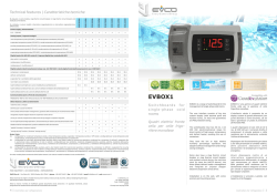
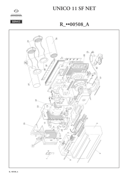
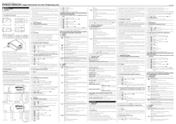
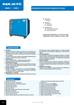
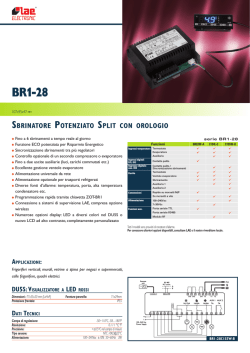
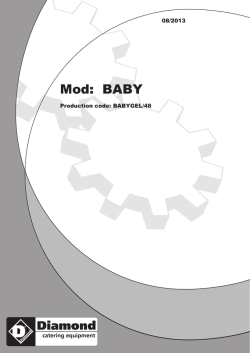
Evco S.p.A. • Code 104KB23A01
EVKB23 and EVKB33
Simple digital thermostats for ventilated refrigerating units
GB ENGLISH
1
GETTING STARTED
1.1 Important
Read these instructions carefully before installing and using the instrument and follow all additional information for installation and electrical
connection; keep these instructions close to the instrument for future
consultations.
The instrument must be disposed according to the local
legislation about the collection for electrical and electronic
equipment.
1.2 Installing the instrument
Panel mounting, with click brackets (supplied by the builder); dimensions in mm (in).
Models with power supply 230 VAC and 115 VAC.
Modelli con alimentazione 230 VCA e 115 VCA.
DIMENS.
A
B
MINIMUM
71.0 (2.795)
29.0 (1.141)
TYPICAL
71.0 (2.795)
29.0 (1.141)
MAXIMUM
71.8 (2.826)
29.8 (1.173)
Additional information for installation:
• 59.0 (2.322) is the maximum depth with screw terminal blocks
• 81.5 (3.208) is the maximum depth with extractable terminal blocks
• the panel thickness must not be higher than 8.0 mm (0.314 in)
• working conditions (working temperature, humidity, etc.) must be between the limits indicated in the technical data
• do not install the instrument close to heating sources (heaters, hot air
ducts, etc.), devices provided with big magnetos (big speakers, etc.),
locations subject to direct sunlight, rain, humidity, dust, mechanical
vibrations or bumps
• according to the safety legislation, the protection against electrical
parts must be ensured by a correct installation of the instrument; the
parts that ensure the protection must be installed so that you can not
remove them if not by using a tool.
1.3 Wiring diagram
With reference to the wiring diagrams: the serial port (by request) is the
port for the communication with the programming key.
Models with power supply 230 VAC and 115 VAC.
Modelli con alimentazione 230 VCA e 115 VCA.
Models with power supply 12 VAC/DC.
Modelli con alimentazione 12 VCA/CC.
Models with power supply 12 VAC/DC.
Modelli con alimentazione 12 VCA/CC.
Additional information for electrical connection:
• do not operate on the terminal blocks with electrical or pneumatic
screwers
• if the instrument has been moved from a cold location to a warm one,
the humidity could condense on the inside; wait about an hour before supplying it
• test the working power supply voltage, working electrical frequency
and working electrical power of the instrument; they must correspond
with the local power supply
• disconnect the local power supply before servicing the instrument
• do not use the instrument as safety device
• for repairs and information on the instrument please contact Evco
sales network.
2
USER INTERFACE
2.1 Preliminary information
There are the following operation status:
• status “on” (the instrument is supplied and is turned on: the regulators
can be turned on)
• status “stand-by” (the instrument is supplied but it is turned off via
software: the regulators are turned off)
• status “off” (the instrument is not supplied).
“Turning on” means moving from status stand-by to status on; “turning
off” means moving from status on to status stand-by.
After an interruption of power supply the instrument moves to the status it was before the interruption.
2.2 Turning on/off the instrument
• make sure the keyboard is not locked and no procedure is running
• press
4 s.
2.3 The display
If the instrument is turned on, during the normal operation the display
will show the cabinet temperature.
If the instrument is turned off, the display will be switched off.
2.4 Showing the evaporator temperature
• make sure the keyboard is not locked and no procedure is running
• press
2 s: the display will show “P2”
• press
To quit the procedure:
• press
or do not operate 60 s
• press
or
as long as the display shows the cabinet
temperature or do not operate 60 s.
If the evaporator probe is not enabled (parameter P3 = 0), the label
“P2” will not be shown.
2.5 Activating the defrost by hand
• make sure the keyboard is not locked and no procedure is running
• press
4 s.
If the function of the evaporator probe is the one of defrost probe (parameter P3 = 1) and to the defrost activation the evaporator temperature is above the one you have set with parameter d2, the defrost will
not be activated.
2.6 Locking/unlocking the keyboard
To lock the keyboard:
• make sure no procedure is running
• press
and
1 s: the display will show “Lo” 1 s.
If the keyboard is locked, you will not be allowed to:
• turn on/off the instrument through button
• show the evaporator temperature
• activate the defrost by hand
• modify the working setpoint with the procedure related in paragraph
3.1 (you also can modify the working setpoint through parameter SP).
These operations provoke the visualization of the label “Lo” 1 s.
To unlock the keyboard:
and
1 s: the display will show “Un” 1 s.
• press
3
SETTINGS
3.1 Setting the working setpoint
• make sure the keyboard is not locked and no procedure is running
• press
: LED
will flash
• press
or
in 15 s; also look at parameters r1 and r2
• press
or do not operate 15 s.
You also can modify the working setpoint through parameter SP.
3.2 Setting configuration parameters
To gain access the procedure (for the models without access password):
• make sure the keyboard is not locked and no procedure is running
• press
and
4 s: the display will show “SP”.
To gain access the procedure (for the models with access password):
• make sure no procedure is running
• press
and
4 s: the display will show “PA”
• press
• press
or
in 15 s to set “-19”
• press
or do not operate 15 s
• press
and
4 s: the display will show “SP”.
To select a parameter:
• press
or
To modify a parameter:
• press
• press
or
in 15
• press
or do not operate 15 s.
To quit the procedure:
• press
and
4 s or do not operate 60 s.
Switch off/on the power supply of the instrument after the
modification of the parameters.
4
SIGNALS
4.1 Signals
LED
MEANING
LED compressor
if it is lit, the compressor will be turned on
if it flashes:
• the modification of the working setpoint will be running
• a compressor protection will be running (parameters C0
and C2)
LED defrost
if it is lit, the defrost will be running
if it flashes:
• the defrost will be required but a compressor protection
will be running (parameters C0 and C2)
• the dripping will be running (parameter d7)
• the heating of the freezing fluid will be running (parameter dA)
LED evaporator fan
if it is lit, the evaporator fan will be turned on
if it flashes, the after dripping evaporator fan delay will be
running (parameter F3)
LED alarm
if it is lit, an alarm or an error will be running
°C
LED Celsius degree
if it is lit, the unit of measure of the temperatures will be
Celsius degree (parameter P2)
°F
LED Fahrenheit degree
if it is lit, the unit of measure of the temperatures will be
Fahrenheit degree (parameter P2)
CODE MEANING
Lo
the keyboard is locked; look at paragraph 2.6
5
ALARMS
5.1 Alarms
CODE MEANING
AL
Lower temperature alarm
Remedies:
• check the cabinet temperature
• look at parameter A1
Effects:
• no effect
AH
Upper temperature alarm
Remedies:
• check the cabinet temperature
• look at parameter A4
Effects:
• no effect
iA
Multipurpose input alarm (only if parameter i5 has value 1
or 2)
Remedies:
• check the reasons that have provoked the activation of
the input
• look at parameters i1 and i5
Effects:
• if parameter i5 has value 1, there will be no effect
• if parameter i5 has value 2, the compressor will be turned
off
version 1.01
id
Door switch input alarm (only if parameter i5 has value 3 or
4)
Remedies:
• check the reasons that have provoked the activation of
the input
• look at parameters i1 and i5
Effects:
• if parameter i5 has value 3, the compressor and the evaporator fan will be turned off
• if parameter i5 has value 4, the evaporator fan will be turned
off
When the cause that has provoked the alarm disappears, the instrument restores the normal operation.
6
INTERNAL DIAGNOSTICS
6.1 Internal diagnostics
CODE MEANING
P1
Cabinet probe error
Remedies:
• check the kind of probe
• check the integrity of the probe
• check the connection instrument-probe
• check the cabinet temperature
Effects:
• in EVKB23 the compressor will be turned on cyclically,
10 min turned on and 10 min turned off; in EVKB33 the
compressor will be turned on
P2
Evaporator probe error
Remedies:
• the same you saw in the previous case but related to the
evaporator probe
Effects:
• if parameter P3 has value 1, the defrost will last the time
you will have set with parameter d3
• if parameter F0 has value 1 or 2, the instrument will work
as if the parameter had value 0
When the cause that has provoked the alarm disappears, the instrument restores the normal operation.
7
TECHNICAL DATA
7.1 Technical data
Box: self-extinguishing grey.
Frontal protection: IP 65.
Connections (use copper conductors only): screw terminal blocks
(power supply, inputs and outputs), 6 poles connector (serial port; by
request); extractable terminal blocks (power supply, inputs and outputs)
by request.
Working temperature: from 0 to 55 °C (32 to 131 °F, 10 ... 90% of
relative humidity without condensate).
Power supply: 230 VAC, 50/60 Hz, 3 VA (approximate); 115 VAC or
12 VAC/DC by request.
Insulation class: 2.
Measure inputs: 2 (cabinet probe and evaporator probe) for
PTC or NTC probes (according to the model).
Digital inputs: 1 (multipurpose/door switch) for NO/NC contact (free
of voltage, 5 V 1 mA).
Working range: from -50 to 150 °C (-50 to 199 °F) for PTC probe,
from -40 to 105 °C (-40 to 199 °F) for NTC probe.
Resolution: 0.1 °C (between -19.9 and 19.9 °C)/1 °C/1 °F.
Digital outputs: 3 relays:
• compressor relay: 30 res. A @ 250 VAC,
12 FLA, 72 LRA in EVKB33; 16 res. A @ 250 VAC,
5 FLA, 30 LRA in EVKB23 with power supply
12 VAC/DC; 8 res. A @ 250 VAC, 2 FLA, 12 LRA
otherwise (NO contact)
• defrost relay: 8 res. A @ 250 VAC, 2 FLA,
12 LRA (NO contact in EVKB33 with power supply
12 VAC/DC; change-over contact otherwise)
• evaporator fan relay: 8 res. A @ 250 VAC,
2 FLA, 12 LRA in EVKB23 with power supply
12 VAC/DC; 5 res. A @ 250 VAC otherwise (NO
contact).
The maximum current allowed on the loads is 10 A.
Serial port: port for the communication with the programming key;
by request.
I ITALIANO
1
PREPARATIVI
1.1 Importante
Leggere attentamente queste istruzioni prima dell’installazione e prima
dell’uso e seguire tutte le avvertenze per l’installazione e per il collegamento elettrico; conservare queste istruzioni con lo strumento per consultazioni future.
Lo strumento deve essere smaltito secondo le normative
locali in merito alla raccolta delle apparecchiature elettriche
ed elettroniche.
1.2 Installazione
A pannello, con le staffe a scatto in dotazione (si vedano i disegni del
paragrafo 1.2 della sezione in Inglese).
Avvertenze per l’installazione:
• 59,0 è la profondità massima con morsettiere a vite
• 81,5 è la profondità massima con morsettiere estraibili
• lo spessore del pannello non deve essere superiore a 8,0 mm
• accertarsi che le condizioni di lavoro (temperatura di impiego, umidità, ecc.) rientrino nei limiti indicati nei dati tecnici
• non installare lo strumento in prossimità di fonti di calore (resistenze,
condotti dell’aria calda, ecc.), di apparecchi con forti magneti (grossi
diffusori, ecc.), di luoghi soggetti alla luce solare diretta, pioggia, umidità, polvere eccessiva, vibrazioni meccaniche o scosse
• in conformità alle normative sulla sicurezza, la protezione contro eventuali contatti con le parti elettriche deve essere assicurata mediante
una corretta installazione dello strumento; tutte le parti che assicurano la protezione devono essere fissate in modo tale da non poter
essere rimosse senza l’aiuto di un utensile.
1.3 Collegamento elettrico
Si vedano i disegni del paragrafo 1.3 della sezione in Inglese.
Con riferimento agli schemi elettrici: la porta seriale (su richiesta) è la
porta per la comunicazione con la chiave di programmazione.
Avvertenze per il collegamento elettrico:
• non operare sulle morsettiere utilizzando avvitatori elettrici o pneumatici
• se lo strumento è stato portato da un luogo freddo a uno caldo,
l’umidità potrebbe condensare all’interno; attendere circa un’ora prima di alimentarlo
• accertarsi che la tensione di alimentazione, la frequenza e la potenza
elettrica operativa dello strumento corrispondano a quelle dell’alimentazione locale
• disconnettere l’alimentazione prima di procedere con qualunque tipo
di manutenzione
• non utilizzare lo strumento come dispositivo di sicurezza
• per le riparazioni e per informazioni riguardanti lo strumento rivolgersi
alla rete di vendita Evco.
2
INTERFACCIA UTENTE
2.1 Cenni preliminari
Esistono i seguenti stati di funzionamento:
• lo stato “on” (lo strumento è alimentato ed è acceso: i regolatori possono essere accesi)
• lo stato “stand-by” (lo strumento è alimentato ma è spento via software:
i regolatori sono spenti)
• lo stato “off” (lo strumento non è alimentato).
Con il termine “accensione” si intende il passaggio dallo stato stand-by
allo stato on; con il termine “spegnimento” si intende il passaggio dallo
stato on allo stato stand-by.
Dopo un’interruzione dell’alimentazione lo strumento passa allo stato in
cui si trovava prima dell’interruzione.
2.2 Accensione/spegnimento dello strumento
• assicurarsi che la tastiera non sia bloccata e che non sia in corso alcuna procedura
per 4 s.
• premere
2.3 Il display
Se lo strumento è acceso, durante il normale funzionamento il display
visualizzerà la temperatura della cella.
Se lo strumento è spento, il display sarà spento.
2.4 Visualizzazione della temperatura dell’evaporatore
• assicurarsi che la tastiera non sia bloccata e che non sia in corso alcuna procedura
• premere
per 2 s: il display visualizzerà “P2”
• premere
Per uscire dalla procedura:
• premere
o non operare per 60 s
• premere
o
fino a quando il display visualizza la temperatura
della cella o non operare per 60 s.
Se la sonda evaporatore è assente (parametro P3 = 0), la label “P2” non
verrà visualizzata.
2.5 Attivazione dello sbrinamento in modo manuale
• assicurarsi che la tastiera non sia bloccata e che non sia in corso alcuna procedura
• premere
per 4 s.
Se la funzione della sonda evaporatore è quella di sonda di sbrinamento
(parametro P3 = 1) e all’attivazione dello sbrinamento la temperatura
dell’evaporatore è al di sopra di quella stabilita con il parametro d2, lo
sbrinamento non verrà attivato.
2.6 Blocco/sblocco della tastiera
Per bloccare la tastiera:
• assicurarsi che non sia in corso alcuna procedura
• premere
e
per 1 s: il display visualizzerà “Lo” per 1 s.
Se la tastiera è bloccata, non sarà consentito:
• accendere/spegnere lo strumento attraverso il tasto
• visualizzare la temperatura dell’evaporatore
• attivare lo sbrinamento in modo manuale
• modificare il setpoint di lavoro con la procedura indicata nel paragrafo
3.1 (il setpoint di lavoro è impostabile anche attraverso il parametro
SP).
Queste operazioni provocano la visualizzazione della label “Lo” per 1 s.
Per sbloccare la tastiera:
• premere
e
per 1 s: il display visualizzerà “Un” per 1 s.
3
IMPOSTAZIONI
3.1 Impostazione del setpoint di lavoro
• assicurarsi che la tastiera non sia bloccata e che non sia in corso alcuna procedura
• premere
: il LED
lampeggerà
• premere
o
entro 15 s; si vedano anche i parametri r1 e r2
• premere
o non operare per 15 s.
È inoltre possibile impostare il setpoint di lavoro attraverso il param. SP.
3.2 Impostazione dei parametri di configurazione
Per accedere alla procedura (per i modelli senza password di accesso):
• assicurarsi che la tastiera non sia bloccata e che non sia in corso alcuna procedura
• premere
e
per 4 s: il display visualizzerà “SP”.
Per accedere alla procedura (per i modelli con password di accesso):
• assicurarsi che non sia in corso alcuna procedura
• premere
e
per 4 s: il display visualizzerà “PA”
• premere
• premere
o
entro 15 s per impostare “-19”
• premere
o non operare per 15 s
• premere
e
per 4 s: il display visualizzerà “SP”.
Per selezionare un parametro:
• premere
o
Per modificare un parametro:
• premere
• premere
o
entro 15 s
• premere
o non operare per 15 s.
Per uscire dalla procedura:
• premere
e
per 4 s o non operare per 60 s.
Interrompere l'alimentazione dello strumento dopo la modifica dei parametri.
4
SEGNALAZIONI
4.1 Segnalazioni
LED
SIGNIFICATO
LED compressore
se è acceso, il compressore sarà acceso
se lampeggia:
• sarà in corso la modifica del setpoint di lavoro
• sarà in corso una protezione del compressore (parametri
C0 e C2)
LED sbrinamento
se è acceso, sarà in corso lo sbrinamento
se lampeggia:
• sarà richiesto lo sbrinamento ma sarà in corso una protezione del compressore (parametri C0 e C2)
• sarà in corso il gocciolamento (parametro d7)
• sarà in corso il risc. del fluido refrigerante (parametro dA)
LED ventilatore dell’evaporatore
se è acceso, il ventilatore dell’evaporatore sarà acceso
se lampeggia, sarà in corso il fermo ventilatore
dell’evaporatore (parametro F3)
LED allarme
se è acceso, sarà in corso un allarme o un errore
°C
LED grado Celsius
se è acceso, l’unità di misura delle temperature sarà il grado
Celsius (parametro P2)
°F
LED grado Fahrenheit
se è acceso, l’unità di misura delle temperature sarà il grado
Fahrenheit (parametro P2)
CODICE SIGNIFICATO
Lo
la tastiera è bloccata; si veda il paragrafo 2.6
5
ALLARMI
5.1 Allarmi
CODICE SIGNIFICATO
AL
Allarme di temperatura di minima
Rimedi:
• verificare la temperatura della cella
• si veda il parametro A1
Conseguenze:
• lo strumento continuerà a funzionare regolarmente
AH
Allarme di temperatura di massima
Rimedi:
• verificare la temperatura della cella
• si veda il parametro A4
Conseguenze:
• lo strumento continuerà a funzionare regolarmente
iA
Allarme ingresso multifunzione (solo se il parametro i5 è impostato a 1 o 2)
Rimedi:
• verificare le cause che hanno provocato l’attivazione dell’ingresso
• si vedano i parametri i1 e i5
Conseguenze:
• se il parametro i5 è impostato a 1, lo strumento continuerà a funzionare regolarmente
• se il parametro i5 è impostato a 2, il compressore verrà
spento
id
Allarme ingresso micro porta (solo se il parametro i5 è impostato a 3 o 4)
Rimedi:
• verificare le cause che hanno provocato l’attivazione dell’ingresso
• si vedano i parametri i1 e i5
Conseguenze:
• se il parametro i5 è impostato a 3, il compressore e il ventilatore dell’evaporatore verranno spenti
• se il parametro i5 è impostato a 4, il ventilatore
dell’evaporatore verrà spento
Quando la causa che ha provocato l’allarme scompare, lo strumento
ripristina il normale funzionamento.
Temperatura di impiego: da 0 a 55 °C (10 ... 90% di umidità relativa senza condensa).
Alimentazione: 230 VCA, 50/60 Hz, 3 VA (approssimativi); 115 VCA
o 12 VCA/CC su richiesta.
Classe di isolamento: 2.
Ingressi di misura: 2 (sonda cella e sonda evaporatore) per sonde
PTC o NTC (a seconda del modello).
Ingressi digitali: 1 (multifunzione/micro porta) per contatto NA/NC
(contatto pulito, 5 V 1 mA).
Campo di misura: da -50 a 150 °C per sonda PTC, da -40 a 105 °C
per sonda NTC.
Risoluzione: 0,1 °C (tra -19,9 e 19,9 °C)/1 °C/1 °F.
Uscite digitali: 3 relè:
• relè compressore: 30 A res. @ 250 VCA, 12 FLA,
72 LRA nell’EVKB33; 16 A res. @ 250 VCA, 5 FLA,
30 LRA nell’EVKB23 con alimentazione 12 VCA/CC;
8 A res. @ 250 VCA, 2 FLA, 12 LRA altrimenti (contatto NA)
• relè sbrinamento: 8 A res. @ 250 VCA, 2 FLA,
12 LRA (contatto NA nell’EVKB33 con alimentazione 12 VCA/CC; contatto in scambio altrimenti)
• relè ventilatore dell’evaporatore: 8 A res. @
250 VCA, 2 FLA, 12 LRA nell’EVKB23 con alimentazione 12 VCA/CC; 5 A res. @ 250 VCA altrimenti
(contatto NA).
La corrente massima consentita sui carichi è di 10 A.
Porta seriale: porta per la comunicazione con la chiave di programmazione; su richiesta.
GB ENGLISH
8
WORKING SETPOINTS AND CONFIGURATION PARAMETERS
8.1 Working setpoints
MIN. MAX. U.M.
DEF.
r1
r2
°C/°F (1) 0.0
8.2 Configuration parameters
PARAM. MIN. MAX. U.M.
DEF.
SP
r1
r2
°C/°F (1) 0.0
PARAM. MIN. MAX. U.M.
DEF.
o1
-25
25
°C/°F (1) 0.0
o2
-25
25
°C/°F (1) 0.0
P1
0
1
--1
WORKING SETPOINTS
working setpoint
WORKING SETPOINTS
working setpoint
MEASURE INPUTS
cabinet probe offset
evaporator probe offset
decimal point Celsius degree (for the quantity to
show during the normal operation, between -9.9
and 19.9 °C)
1 = YES
unit of measure temperature (2)
0 = °C
1 = °F
evaporator probe function
0 = probe not enabled
1 = defrost probe and thermostat probe for the
evaporator fan
2 = thermostat probe for the evaporator fan
P2
0
1
---
0
P3
0
2
---
1
PARAM. MIN.
r0
0.1
r1
-99
r2
r1
PARAM. MIN.
C0
0
MAX.
15.0
r2
199
MAX.
199
U.M.
°C/°F (1)
°C/°F (1)
°C/°F (1)
U.M.
min
DEF.
2.0
(3)
50
DEF.
0
MAIN REGULATOR
working setpoint differential
minimum working setpoint
maximum working setpoint
COMPRESSOR PROTECTIONS
compressor delay since you turn on the instrument
C2
0
C3
0
PARAM. MIN.
d0
0
199
199
MAX.
99
min
s
U.M.
h
3
0
DEF.
8
minimum time the compressor remains turned off
minimum time the compressor remains turned on
DEFROST
defrost interval
0 = the defrost at intervals will never be activated
d1
0
1
---
0
d2
d3
-99
0
99
99
°C/°F (1) 2.0
min
30
d4
0
1
---
0
d5
0
199
min
0
d6
0
1
---
1
kind of defrost
0 = electric defrost
1 = hot gas defrost
defrost cutoff temperature (only if P3 = 1)
if P3 = 0 or 2, defrost duration
if P3 = 1, defrost maximum duration
0 = the defrost will never be activated
defrost when you turn on the instrument
1 = YES
defrost delay when you turn on the instrument
(only if d4 = 1)
temperature shown during the defrost
0 = cabinet temperature
1 = if to the defrost activation the cabinet temperature is below “working setpoint + r0”, at most
“working setpoint + r0”; if to the defrost activation the cabinet temperature is above “working setpoint + r0”, at most the cabinet temperature to the defrost activation (4)
d7
dA
0
0
15
99
min
min
2
0
dripping duration
minimum time the compressor must be remained
turned on (to the defrost activation) in order that
the defrost can be activated (only if d1 = 1) (5)
ITALIANO
SETPOINT DI LAVORO E PARAMETRI
DI CONFIGURAZIONE
8.1 Setpoint di lavoro
SETPOINT DI LAVORO
setpoint di lavoro
8.2 Parametri di configurazione
SETPOINT DI LAVORO
setpoint di lavoro
INGRESSI DI MISURA
offset sonda cella
offset sonda evaporatore
punto decimale grado Celsius (per la grandezza
visualizzata durante il normale funzionamento, tra
-9,9 e 19,9 °C)
1 = SI
unità di misura temperatura (2)
0 = °C
1 = °F
funzione della sonda evaporatore
0 = sonda assente
1 = sonda di sbrinamento e sonda per la
termostatazione del ventilatore dell’evaporatore
2 = sonda per la termostatazione del ventilatore
dell’evaporatore
REGOLATORE PRINCIPALE
differenziale del setpoint di lavoro
minimo setpoint di lavoro
massimo setpoint di lavoro
PROTEZIONI DEL COMPRESSORE
ritardo compressore dall’accensione dello strumento
durata minima dello spegnimento del compressore
durata minima dell’accensione del compressore
SBRINAMENTO
intervallo di sbrinamento
0 = lo sbrinamento a intervalli non verrà mai attivato
tipo di sbrinamento
0 = elettrico
1 = a gas caldo
temperatura di fine sbrinamento (solo se P3 = 1)
se P3 = 0 o 2, durata dello sbrinamento
se P3 = 1, durata massima dello sbrinamento
0 = lo sbrinamento non verrà mai attivato
sbrinamento all’accensione dello strumento
1 = SI
ritardo sbrinamento dall’accensione dello strumento (solo se d4 = 1)
temperatura visualizzata durante lo sbrinamento
0 = temperatura della cella
1 = se all’attivazione dello sbrinamento la temperatura della cella è al di sotto di “setpoint di lavoro + r0”, al massimo “setpoint di lavoro + r0”; se
all’attivazione dello sbrinamento la temperatura della cella è al di sopra di “setpoint di lavoro
+ r0”, al massimo la temperatura della cella all’attivazione dello sbrinamento (4)
durata del gocciolamento
durata minima dell’accensione del compressore all’attivazione dello sbrinamento affinchè questi possa essere attivato (solo se d1 = 1) (5)
8
PARAM. MIN.
A1
0.0
MAX.
199
U.M.
DEF.
°C/°F (1) 10.0
TEMPERATURE ALARMS (6) (7)
temperature below which the lower temperature
alarm is activated (relative to the working setpoint
or "working setpoint - A1”) (8)
0.0 = alarm not enabled
A4
0.0
199
°C/°F (1)
10.0
temperature above which the upper temperature
alarm is activated (relative to the working setpoint
or "working setpoint + A4”) (8)
0.0 = alarm not enabled
A6
0
199
min
120
A7
0
PARAM. MIN.
F0
0
199
MAX.
2
min
U.M.
---
15
DEF.
2
upper temperature alarm delay since you turn on
the instrument
temperature alarm delay
EVAPORATOR FAN
evaporator fan activity during the normal operation
0 = according to the compressor
1 = according to F1 (9)
2 = turned off if the compressor is turned off, according to F1 if the compressor is turned on (9)
F1
-99
99
°C/°F (1)
-1.0
evaporator temperature above which the evaporator fan is turned off (only if F0 = 1 or 2) (8)
F2
0
1
---
0
F3
0
PARAM. MIN.
i1
0
15
MAX.
1
min
U.M.
---
2
DEF.
0
i3
-1
120
min
15
i5
0
4
---
4
evaporator fan activity during the defrost and the
dripping
0 = turned off
1 = turned on
duration of the after dripping evaporator fan delay
DIGITAL INPUTS
kind of contact digital input
0 = NO (the input will be active if you close the
contact)
1 = NC (the input will be active if you open the
contact)
maximum duration of the effect provoked by the
activation of the door switch input on the loads (only
if i5 = 3 or 4)
-1 = the effect will last as long as the input will be
deactivated
kind of digital input (effect provoked by the activation of the digital input)
0 = no effect
1 = MULTIPURPOSE (activation external alarm) spent the time i7 the display will show the code
“iA” flashing (as long as the input will be deactivated)
2 = MULTIPURPOSE (activation manostat) - the compressor will be turned off and the display will
show the code “iA” flashing (as long as the
input will be deactivated); also look at i7
3 = DOOR SWITCH INPUT (compressor and evaporator fan turned off) - the compressor and the
evaporator fan will be turned off (at most for
the time i3 or as long as the input will be deactivated) and spent the time i7 the display will
show the code “id” flashing (as long as the input will be deactivated) (10)
4 = DOOR SWITCH INPUT (evaporator fan turned
off) - the evaporator fan will be turned off (at
most for the time i3 or as long as the input will
be deactivated) and spent the time i7 the display will show the code “id” flashing (as long
as the input will be deactivated)
i7
-1
120
min
30
(1)
(2)
the unit of measure depends on parameter P2
set the parameters related to the regulators appropriately after the
modification of the parameter P2
the value depends on the kind of model (-50 for the models for PTC probe, -40 for the
models for NTC probe)
the display restores the normal operation as soon as the after dripping evaporator fan
delay ends and the cabinet temperature falls below the one that has locked the display
(or if a temperature alarm arises)
if (to the defrost activation) the duration of the activation of the compressor is shorter
than the time you have set with parameter dA, the compressor will further remain turned
on the fraction of time required to complete it
during the defrost, the dripping and the evaporator fan delay the temperature alarms
are not enabled, on condition that they have arisen after the activation of the defrost
during the activation of the door switch input the upper temperature alarm is not
enabled, on condition that it has arisen after the activation of the input
I
(3)
(4)
(5)
(6)
(7)
PT • 51/10
6
DIAGNOSTICA INTERNA
6.1 Diagnostica interna
CODICE SIGNIFICATO
P1
Errore sonda cella
Rimedi:
• verificare il tipo di sonda
• verificare l’integrità della sonda
• verificare il collegamento strumento-sonda
• verificare la temperatura della cella
Conseguenze:
• nell’EVKB23 il compressore verrà acceso in modo ciclico,
10 min acceso e 10 min spento; nell’EVKB33 il compressore verrà acceso
P2
Errore sonda evaporatore
Rimedi:
• gli stessi del caso precedente ma relativamente alla sonda
evaporatore
Conseguenze:
• se il parametro P3 è impostato a 1, lo sbrinamento durerà
il tempo stabilito con il parametro d3
• se il parametro F0 è impostato a 1 o 2, lo strumento funzionerà come se il parametro fosse impostato a 0
Quando la causa che ha provocato l’allarme scompare, lo strumento
ripristina il normale funzionamento.
7
DATI TECNICI
7.1 Dati tecnici
Contenitore: autoestinguente grigio.
Grado di protezione del frontale: IP 65.
Connessioni (usare solo conduttori in rame): morsettiere a vite
(alimentazione, ingressi e uscite), connettore a 6 poli (porta seriale; su
richiesta); morsettiere estraibili (alimentazione, ingressi e uscite) su rich.
if i5 = 1, delay to signal the multipurpose input alarm
-1 = no signal
if i5 = 2, compressor delay since the deactivation of
the multipurpose input (11)
if i5 = 3, delay to signal the door switch input alarm
-1 = no signal
EVCO S.p.A.
Via Mezzaterra 6, 32036 Sedico Belluno ITALY
Phone +39-0437-852468 • Fax +39-0437-83648
[email protected] • www.evco.it
ALLARMI DI TEMPERATURA (6) (7)
temperatura al di sotto della quale viene attivato
l’allarme di temperatura di minima (relativo al
setpoint di lavoro ovvero “setpoint di lavoro - A1”)
(8)
0.0 = allarme assente
temperatura al di sopra della quale viene attivato
l’allarme di temperatura di massima (relativo al
setpoint di lavoro ovvero “setpoint di lavoro + A4”)
(8)
0.0 = allarme assente
ritardo allarme di temperatura di massima dall’accensione dello strumento
ritardo allarme di temperatura
VENTILATORE DELL’EVAPORATORE
attività del ventilatore dell’evaporatore durante il
normale funzionamento
0 = parallelamente al compressore
1 = dipendente da F1 (9)
2 = spento se il compressore è spento, dipendente
da F1 se il compressore è acceso (9)
temperatura dell’evaporatore al di sopra della quale il ventilatore dell’evaporatore viene spento (solo
se F0 = 1 o 2) (8)
attività del ventilatore dell’evaporatore durante lo
sbrinamento e il gocciolamento
0 = spento
1 = acceso
durata del fermo ventilatore dell’evaporatore
INGRESSI DIGITALI
tipo di contatto dell’ingresso digitale
0 = NA (ingresso attivo con contatto chiuso)
1 = NC (ingresso attivo con contatto aperto)
(8)
(9)
(10)
(11)
(5)
the differential of the parameter is 2.0 °C/4 °F
if parameter P3 has value 0, the instrument will work as if parameter F0 had value 0
the compressor is turned off spent 10 s since the activation of the input; if the input is
activated during the defrost or the after dripping evaporator fan delay, the activation
will provoke no effect on the compressor
if parameter i5 has value 2 and parameter i7 has value -1, the instrument will work as if (6)
parameter i7 had value 0.
se all’attivazione dello sbrinamento la durata
dell’accensione del compressore è inferiore al
tempo stabilito con il parametro dA, il compressore rimarrà ulteriormente acceso per la
frazione di tempo necessaria a completarlo
durante lo sbrinamento, il gocciolamento e il
fermo ventilatore dell'evaporatore gli allarmi
di temperatura sono assenti, a condizione che
questi si siano manifestati dopo l’attivazione
dello sbrinamento
(7) durante l’attivazione dell’ingresso micro porta
l’allarme di temperatura di massima è assente,
a condizione che questi si sia manifestato dopo
l’attivazione dell’ingresso
(8) il differenziale del parametro è di 2,0 °C/4 °F
(9) se il parametro P3 è impostato a 0, lo strumento funzionerà come se il parametro F0
fosse impostato a 0
(10) il compressore viene spento trascorsi 10 s dall’attivazione dell’ingresso; se l’ingresso viene
attivato durante lo sbrinamento o il fermo ventilatore dell’evaporatore, l’attivazione non provocherà alcun effetto sul compressore
(11) se il parametro i5 è impostato a 2 e il parametro i7 è impostato a -1, lo strumento funzionerà come se il parametro i7 fosse impostato a
0.
durata massima dell’effetto provocato dall'attivazione dell’ingresso micro porta sui carichi (solo se
i5 = 3 o 4)
-1 = l’effetto durerà fino a quando l’ingresso verrà
disattivato
tipo di ingresso digitale (effetto provocato dall'attivazione dell’ingresso digitale)
0 = nessun effetto
1 = INGRESSO MULTIFUNZIONE (attivazione allarme esterno) - trascorso il tempo i7 il display
visualizzerà il codice “iA” lampeggiante (fino a
quando l’ingresso verrà disattivato)
2 = INGRESSO MULTIFUNZIONE (intervento
pressostato) - il compressore verrà spento e il
display visualizzerà il codice “iA” lampeggiante
(fino a quando l’ingresso verrà disattivato); si
veda anche i7
3 = INGRESSO MICRO PORTA (compressore e ventilatore dell’evaporatore spenti) - il compressore
e il ventilatore dell’evaporatore verranno spenti
(al massimo per il tempo i3 o fino a quando
l’ingresso verrà disattivato) e trascorso il tempo
i7 il display visualizzerà il codice “id” lampeggiante (fino a quando l’ingresso verrà disattivato)
(10)
4 = INGRESSO MICRO PORTA (ventilatore
dell’evaporatore spento) - il ventilatore
dell’evaporatore verrà spento (al massimo per il
tempo i3 o fino a quando l’ingresso verrà
disattivato) e trascorso il tempo i7 il display
visualizzerà il codice “id” lampeggiante (fino a
quando l’ingresso verrà disattivato)
se i5 = 1, ritardo segnalazione allarme ingresso
multifunzione
-1 = l’allarme non verrà segnalato
se i5 = 2, ritardo compressore dalla disattivazione
dell’ingresso multifunzione (11)
se i5 = 3 o 4, ritardo segnalazione allarme ingresso
micro porta
-1 = l’allarme non verrà segnalato
(1) l’unità di misura dipende dal parametro P2
(2) impostare opportunamente i parametri relativi ai regolatori dopo la modifica del parametro P2
(3) il valore dipende dal tipo di modello (-50 per i
modelli per sonda PTC, -40 per i modelli per
sonda NTC)
(4) il display ripristina il normale funzionamento
quando, concluso il fermo ventilatore
dell’evaporatore, la temperatura della cella
scende al di sotto di quella che ha bloccato il
display (o se si manifesta un allarme di temperatura)
This document belongs to Evco; unless you are authorized by Evco, you can not publish it.
Evco does not take any responsibility about features, technical data and possible mistakes related in this document or coming by its use.
Evco does not take any responsibility about damages coming by the non-observance of the additional information.
Evco reserves the right to make any change without prior notice and at any time without prejudice the basic safety and operating features.
© Copyright 2026 Paperzz