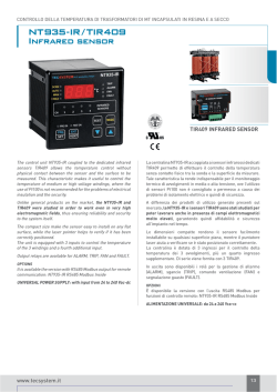
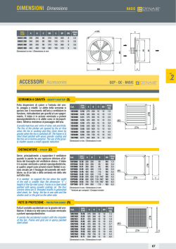
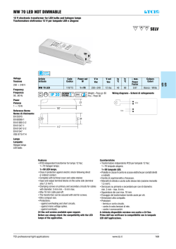
TEMPERATURE CONTROL OF MV DRY TYPE AND CAST RESIN TRANSFORMERS
VRT SERIES
SERIE VRT
The series consists of three VRT devices specially developed
for the control of electric motors, particularly those fitted
to the ventilation systems, able to diagnose motor faults by
evaluating changes in current drawn by the same. Protection
and operation of ventilation systems for cast resin
transformers are integrated in one device.
The product range is made of three devices:
VRT200: basic model with 2 outputs, able to drive 3 fans each
VRT300: 3 outputs version, able to drive 3 fans
VRT600: 6 outputs version, able to drive 6 fans
All units are equipped with leds for visual anomalies indication
and FAULT relay for signal anomalies.
Fans can be driven remotely (dry contact input) or “locally” via
the front push button.
OPTIONS
VRT-U version 12 Vac-dc: input for motor power from 85 to
260 Vac
POWER SUPPLY: 230 Vac ± 10% 50/60 Hz
La serie VRT è composta da tre dispositivi appositamente
sviluppati per il pilotaggio di motori elettrici, in particolare
per quelli che equipaggiano i sistemi di ventilazione, in grado
di diagnosticare eventuali malfunzionamenti dei motori
analizzando le variazioni della corrente assorbita dagli stessi.
La protezione e l’azionamento dei sistemi di ventilazione per
trasformatori in resina sono integrati in un solo dispositivo.
La gamma è composta da tre modelli:
VRT200: modello base con 2 uscite, in grado di pilotare 3
ventilatori ciascuna
VRT300: versione a 3 uscite, in grado di pilotare 3 singoli
ventilatori
VRT600: versione con 6 uscite, in grado di pilotare singolarmente
6 ventilatori
Tutte le centraline sono dotate di led per l’indicazione visiva
delle anomalie e relè di FAULT per la segnalazione anomalie.
L’azionamento dei ventilatori può avvenire da remoto (ingresso da
contatto pulito) o in “locale” tramite tasto di azionamento frontale.
OPZIONI
Versione VRT-U 12 Vca-cc: disponibile con range di alimentazione
motori da 85 a 260 Vca
ALIMENTAZIONE: 230 Vca ± 10% 50/60 Hz
28
www.tecsystem.it
CONTROLLO DELLA TEMPERATURA DI TRASFORMATORI DI MT INCAPSULATI IN RESINA E A SECCO
TECHNICAL SPECIFICATIONS
SPECIFICHE TECNICHE
VRT200
VRT200
POWER SUPPLY
Rated values: 230 Vac ± 10% 50/60 Hz
Burden: 5VA (max)
ALIMENTAZIONE
Valori nominali: 230 Vca ± 10% 50/60 Hz
Assorbimento: 5VA (max)
INPUTS
1 contact to enable the remote control (ENABLE)
2 inputs to check the temperature by Ptc or auxiliary contact.
Removable rear terminals
INGRESSI
1 contatto di abilitazione gestione remota (ENABLE)
2 ingressi per controllo temperatura con Ptc o contatto aux.
Collegamenti su morsettiere estraibili
OUTPUTS
1 alarm and fault relay (ALARM/FAULT)
Output relay capacity: 5A-250 Vac cosϕ=1
Outputs M1-M2: 230 Vac±10%, 2x5 A max., 50-60 Hz
USCITE
1 relè allarme e guasto (ALARM/FAULT)
Relè di uscita con contatti da 5A-250 Vca cosϕ=1
Uscite M1-M2: 230 Vca±10%, 2x5 A max., 50-60 Hz
TESTS AND PERFORMANCES
Assembling in accordance with CEI EN61000-4-4
Dielectric strength: 2500 Vac for 1 minute:
supply-relay fault, supply-remote
Ambient operating temperature: from -20°C to + 60°C
Humidity: 90% non-condensing
Self-extinguishing housing NORYL 94V0
Option: tropicalization
Vibration test IEC 68-2-6:
• Amplitude ± 1 mm from 2Hz to 13.2Hz
• Acceleration ± 0.7G from 13.2Hz to100Hz
Sismic test according to IEEE 344-1.987
Frontal in polycarbonate IP65
TEST E PRESTAZIONI
Costruzione in accordo alle normative CEI EN61000-4-4
Rigidità dielettrica: 2500 Vca per 1 minuto:
alimentazione-relè fault, alimentazione-remote
Temperatura di lavoro: da -20°C a + 60°C
Umidità ammessa: 90% senza condensa
Contenitore in NORYL 94V0 autoestinguente
Opzione: tropicalizzazione
Test di vibrazioni IEC 68-2-6:
• Ampiezza ± 1 mm da 2Hz a 13.2Hz
• Accelerazione ± 0.7G da 13.2Hz a 100Hz
Test sismico secondo la normativa IEEE 344-1.987
Frontale in policarbonato IP65
DISPLAYING AND DATA MANAGEMENT
Alarm leds: undercurrent, overcurrent, overtemp-aux stop
Running, remote, local leds
Prg, prg setting, cal. leds
Starting AUTO-TUNING for motor protection set-up
Front key for manual START/STOP of the motors
Front alarm reset key
Programming access through front key
VISUALIZZAZIONE E GESTIONE DATI
Led allarme: undercurrent, overcurrent, overtemp-aux stop
Led running, remote, local
Led prg, prg setting, cal.
AUTO-TUNING iniziale di impostazione protezione motori
Tasto frontale per lo START/STOP manuale dei motori
Tasto frontale per il reset degli allarmi
Accesso alla programmazione tramite tasto frontale
DIMENSIONS
100 x 100 mm DIN 43700 depth 130 mm (terminals included)
Panel cut-out 92 x 92 mm
DIMENSIONI
100 x 100 mm DIN 43700 prof. 130 mm (compreso morsettiera)
Foro pannello 92 x 92 mm
VRT200
5 Amp - 230 Vac
5 Amp - 230 Vac
ELECTRICAL CONNECTIONS
VRT200
VRT200-U
COLLEGAMENTI ELETTRICI
VRT200
VRT200-U
FAN CONTROL OUTPUT
USCITA CONTROLLO VENTILAZIONE
FAN CONTROL OUTPUT
USCITA CONTROLLO VENTILAZIONE
42 FAN LINE POWER SUPPLY
41 ALIMENTAZIONE LINEA FAN
FAN INPUT
INGRESSO FAN
OUTPUTS ALARM RELAYS
USCITE RELÈ DI ALLARME
www.tecsystem.it
85-260 VAC 10A MAX
40 85-260 VCA 10A MAX
POWER SUPPLY
ALIMENTAZIONE
230 VAC 50/60 Hz
230 VCA 50/60 Hz
10A max
MAX
5A 230 Vac
MAX
5A 230 Vac
42 POWER SUPPLY
41
85-260 VAC/DC 5A MAX 2 OUTPUTS
2 USCITE 85-260 VCA/CC 5A MAX
ALIMENTAZIONE
12 VAC/DC
40 12 VCA/CC
29
TEMPERATURE CONTROL OF MV DRY TYPE AND CAST RESIN TRANSFORMERS
TECHNICAL SPECIFICATIONS
SPECIFICHE TECNICHE
VRT300
VRT300
POWER SUPPLY
Rated values: 230 Vac ± 10% 50/60 Hz
Burden: 5 VA
ALIMENTAZIONE
Valori nominali: 230 Vca ± 10% 50/60 Hz
Assorbimento: 5 VA
INPUTS
1 line input FAN 230 Vac±10%, 15 A max., 50-60 Hz
1 contact to enable the remote control (ENABLE)
Removable rear terminals (except FAN lines)
INGRESSI
1 ingresso linea FAN 230 Vca±10%,15 A max., 50-60 Hz
1 contatto di abilitazione gestione remota (ENABLE)
Collegamenti su morsettiere estraibili (esclusa linea FAN)
OUTPUTS
1 alarm and fault relay (ALARM/FAULT)
Output relay capacity: 5A-250 Vac cosϕ=1
Outputs: M1-M2-M3: 230 Vac±10%, 3x5 A max., 50-60 Hz
USCITE
1 relè allarme e guasto (ALARM/FAULT)
Relè di uscita con contatti da 5A-250 Vca cosϕ=1
Uscite: M1-M2-M3: 230 Vca±10%, 3x5 A max., 50-60 Hz
TESTS AND PERFORMANCES
Assembling in accordance with CEI-EN61000-4-4
Dielectric strength 2500 Vac for 1 minute:
supply-relay fault, supply-remote
Ambient operating temperature: from -20°C to + 60°C
Humidity: 90% non-condensing
Self-extinguishing housing NORYL 94V0
Option: tropicalization
Vibration test IEC 68-2-6:
• Amplitude ± 1 mm from 2Hz to 13.2Hz
• Acceleration ± 0.7G from 13.2Hz to100Hz
Sismic test according to IEEE 344-1.987
Frontal in polycarbonate IP65
TEST E PRESTAZIONI
Costruzione in accordo alle normative CEI-EN61000-4-4
Rigidità dielettrica: 2500 Vca per 1 minuto:
alimentazione-relè fault, alimentazione-remote
Temperatura di lavoro: da -20°C a + 60°C
Umidità ammessa: 90% senza condensa
Contenitore in NORYL 94V0 autoestinguente
Opzione: tropicalizzazione
Test di vibrazioni IEC 68-2-6:
• Ampiezza ± 1 mm da 2Hz a 13.2Hz
• Accelerazione ± 0.7G da 13.2Hz a 100Hz
Test sismico secondo la normativa IEEE 344-1.987
Frontale in policarbonato IP65
DISPLAYING AND DATA MANAGEMENT
Alarm leds: undercurrent, overcurrent, overtemp
Running remote, local leds
Prg, prg setting, cal. leds
Starting AUTO-TUNING for motor protection set-up
Front key for manual START/STOP of the motors
Front alarm reset key
Programming access through front key
VISUALIZZAZIONE E GESTIONE DATI
Led allarme: undercurrent, overcurrent.
Led running, remote, local
Led prg, prg setting, cal.
AUTO-TUNING iniziale di impostazione protezione motori
Tasto frontale per lo START/STOP manuale dei motori
Tasto frontale per il reset degli allarmi
Accesso alla programmazione tramite tasto frontale
DIMENSIONS
100 x 100 mm DIN 43700 depth 130 mm (terminals included)
Panel cut-out 92 x 92 mm
DIMENSIONI
100 x 100 mm DIN 43700 prof. 130 mm (compreso morsettiera)
Foro pannello 92 x 92 mm
VRT300
Tot.: 15 Amp - 230 Vac
ELECTRICAL CONNECTIONS
VRT300
VRT300-U
COLLEGAMENTI ELETTRICI
VRT300
VRT300-U
A
A
POWER SUPPLY VRT
ALIMENTAZIONE VRT
230 VAC 50/60 Hz
230 VCA 50/60 Hz
FAN CONTROL OUTPUT
USCITA CONTROLLO VENTILAZIONE
FAN INPUT
INGRESSO FAN
FAN CONTROL OUTPUT
USCITA CONTROLLO VENTILAZIONE
B
OUTPUTS ALARM RELAYS
USCITE RELÈ DI ALLARME
30
3x5A 230 Vac
B
FAN LINE POWER SUPPLY
ALIMENTAZIONE LINEA FAN
230 VAC 50/60 Hz
230 VCA 50/60 Hz
15A max
1
2
3
www.tecsystem.it
CONTROLLO DELLA TEMPERATURA DI TRASFORMATORI DI MT INCAPSULATI IN RESINA E A SECCO
TECHNICAL SPECIFICATIONS
SPECIFICHE TECNICHE
VRT600
VRT600
POWER SUPPLY
Rated values 230 Vac ± 10% 50/60 Hz
Burden: 7,5 VA
ALIMENTAZIONE
Valori nominali 230 Vca ± 10% 50/60 Hz
Assorbimento: 7,5 VA
INPUTS
2 lines input FAN 230 Vac±10%, 30 A max., 50-60 Hz
1 contact to enable the remote control (ENABLE)
Removable rear terminals (except FAN lines)
INGRESSI
2 ingressi linea FAN 230 Vca±10%, 30 A max., 50-60 Hz
1 contatto di abilitazione gestione remota (ENABLE)
Collegamenti su morsettiere estraibili (esclusa linea FAN)
OUTPUTS
1 alarm and fault relay (ALARM/FAULT)
Output relay capacity: 5A-250 Vac cosϕ=1
Outputs: M1-M2-M3-M4-M5-M6: 230 Vac±10%, 6x5 A max., 50-60 Hz
USCITE
1 relè allarme e guasto (ALARM/FAULT)
Relè di uscita con contatti da 5A-250 Vca cosϕ=1
Uscite: M1-M2-M3-M4-M5-M6: 230 Vca±10%, 6x5 A max., 50-60 Hz
TESTS AND PERFORMANCES
Assembling in accordance with CEI-EN61000-4-4
Dielectric strength 2500 Vac for 1 minute:
supply-relay fault, supply-remote
Ambient operating temperature: from -20°C to + 60°C
Humidity: 90% non-condensing
Self-extinguishing housing NORYL 94V0
Option: tropicalization
Vibration test IEC 68-2-6:
• Amplitude ± 1 mm from 2Hz to 13.2Hz
• Acceleration ± 0.7G from 13.2Hz to100Hz
Sismic test according to IEEE 344-1.987
Frontal in polycarbonate IP65
TEST E PRESTAZIONI
Costruzione in accordo alle normative CEI-EN61000-4-4
Rigidità dielettrica: 2500 Vca per 1 minuto:
alimentazione-relè fault, alimentazione-remote
Temperatura di lavoro: da -20°C a + 60°C
Umidità ammessa: 90% senza condensa
Contenitore in NORYL 94V0 autoestinguente
Opzione: tropicalizzazione
Test di vibrazioni IEC 68-2-6:
• Ampiezza ± 1 mm da 2Hz a 13.2Hz
• Accelerazione ± 0.7G da 13.2Hz a 100Hz
Test sismico secondo la normativa IEEE 344-1.987
Frontale in policarbonato IP65
DISPLAYING AND DATA MANAGEMENT
Alarm leds: undercurrent, overcurrent, overtemp
Running remote, local leds
Prg, prg setting, cal. leds
Starting AUTO-TUNING for motor protection set-up
Front key for manual START/STOP of the motors
Front alarm reset key
Programming access through front key
VISUALIZZAZIONE E GESTIONE DATI
Led allarme: undercurrent, overcurrent
Led running, remote, local
Led prg, prg setting, cal.
AUTO-TUNING iniziale di impostazione protezione motori
Tasto frontale per lo START/STOP manuale dei motori
Tasto frontale per il reset degli allarmi
Accesso alla programmazione tramite tasto frontale
DIMENSIONS
100 x 100 mm DIN 43700 depth 130 mm (terminals included)
Panel cut-out 92 x 92 mm
DIMENSIONI
100 x 100 mm DIN 43700 prof. 130 mm (compreso morsettiera)
Foro pannello 92 x 92 mm
VRT600
Tot.: 30 Amp - 230 Vac
ELECTRICAL CONNECTIONS
VRT600
VRT600-U
COLLEGAMENTI ELETTRICI
VRT600
FAN CONTROL OUTPUTS LINE 1
LINEA 1 USCITE CONTROLLO VENTILAZIONE
43 44 45 46 47 48
M1
61 60
FAN INPUT
INGRESSO FAN
5A
M3
M2
2
V
VRT600-U
A
42
41
40
40
FAN CONTROL OUTPUTS LINE 2
LINEA 2 USCITE CONTROLLO VENTILAZIONE
49 50 51 52 53 54
41
42
M4
5A
www.tecsystem.it
M6
M5
2
V
FAN LINE 1 POWER SUPPLY
ALIMENTAZIONE LINEA 1 FAN
230 VAC 50/60 Hz 15A max
B2
40
OUTPUTS ALARM RELAYS
POWER SUPPLY VRT
ALIMENTAZIONE VRT
230 VAC 50/60 Hz
230 VCA 50/60 Hz
41
42
FAN LINE 2 POWER SUPPLY
ALIMENTAZIONE LINEA 2 FAN
230 VAC 50/60 Hz 15A max
FAN CONTROL OUTPUTS LINE 1
LINEA 1 USCITE CONTROLLO VENTILAZIONE
43 44 45 46 47 48
M1
M2
M3
85-260 VAC/DC 5A MAX 3 OUTPUTS
3 USCITE 85-260 VCA/CC 5A Max
FAN CONTROL OUTPUTS LINE 2
LINEA 2 USCITE CONTROLLO VENTILAZIONE
49 50 51 52 53 54
A
42
41
40
42
41
40
B2
42
M4
M5
M6
85-260 VAC/DC 5A MAX 3 OUTPUTS
3 USCITE 85-260 VCA/CC 5A Max
41
40
POWER SUPPLY
ALIMENTAZIONE
12 VAC/DC
12 VCA/CC
FAN LINE 1 POWER SUPPLY
ALIMENTAZIONE LINEA 1 FAN
85-260 VAC 15A MAX
85-260 VCA 15A MAX
FAN LINE 2 POWER SUPPLY
ALIMENTAZIONE LINEA 2 FAN
85-260 VAC 15A MAX
85-260 VCA 15A MAX
31
© Copyright 2026 Paperzz