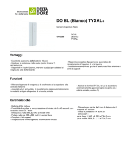
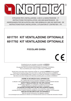
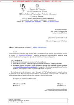
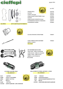
ISTRUZIONI PER L’INSTALLAZIONE, L’USO E LA MANUTENZIONE - IT
INSTRUCTIONS FOR INSTALLATION, USE AND MAINTENANCE - EN
ANWEISUNGEN FÜR DIE AUFSTELLUNG, DEN GEBRAUCH UND DIE WARTUNG - DE
INSTRUCTIONS POUR L’INSTALLATION, L’UTILISATION ET L’ENTRETIEN – FR
1318000 KIT VENTILAZIONE OPTIONALE
FALÒ – INSERTI – FOCOLARE 80
FOCOLARE 100 Bifacciale
|
Complimenti per aver acquistato un prodotto: La NORDICA.
Congratulations for purchasing a product by: La NORDICA.
Wir gratulieren Sie für den Einkauf eines Einsatzes in Gusseisen: La NORDICA.
Nous vous félicitons pour l’achat d’un poêle à bois LA NORDICA!
•
Sentirsi bene e allo stesso tempo risparmiare energia con i prodotti La NORDICA diventa possibile!
Feeling well and sparing energy at the same time is a reality with the products by La NORDICA
Sich wohl zu fühlen und gleichzeitig Energie zu sparen ist nun dank den Produkten La NORDICA möglich!
Bien-être et économie d’énergie sont désormais possibles grâce aux produits LA NORDICA!
NORME DI SICUREZZA SUGLI APPARECCHI
Per il rispetto delle norme di sicurezza è obbligatorio installare
e utilizzare i nostri prodotti seguendo scrupolosamente le indicazioni fornite nel presente manuale.
SAFETY REGULATIONS ON THE APPLIANCES
To meet safety regulations, it is compulsory to install and use our products
carefully following the instructions contained in this manual.
SICHERHEITSVORSCHRIFTEN BEI DEN AUSRÜSTUNGEN
Um die Sicherheitsvorschriften zu beachten, ist es notwendig, unsere Produkte
vorsichtig nach den in diesem Handbuch enthaltenen Anweisungen zu installieren und anzuwenden.
RÉGLÉS DE SÉCURITÉ SUR LES APPAREILS
Selon les normes de sécurité sur les appareils l’acheteur
et le commerçant sont contraints de s’informer sur le fonctionnement correct sur la base des instructions d’emploi.
1391005 KIT VENTILAZIONE OPTIONALE
INFORMAZIONI AL UTENTE SULLO SMALTIMENTO DELLE APPARECCHIATURE DA PARTE DEI PRIVATI
NEL TERRITORIO DELL’UNIONE EUROPEA
Ai sensi dell’art.13 del decreto legislativo 25 luglio 2005, n.151 «attuazione delle direttive 2002/95/CE e 2003/1 08/
CE, relative sostanze alla riduzione dell’uso di sostanze pericolose nelle apparecchiature elettriche ed elettroniche,
nonché allo smaltimento dei rifiuti». il simbolo del cassonetto barrato riportato sull’apparecchiatura o sulla confezione
indica che il prodotto alla fine della propria vita utile deve essere raccolto separatamente dagli altri rifiuti. l’utente dovrà,
pertanto, conferire l’apparecchiatura giunta a fine vita agli idonei centri di raccolta differenziata dei
rifiuti elettronici ed elettrotecnici, oppure riconsegnarla al rivenditore al momento dell’acquisto di una
nuova apparecchiatura di tipo equivalente, in ragione di uno a uno. L’adeguata raccolta differenziata
per l’awio successivo dell’apparecchiatura e dismessa al riciclaggio, al trattamento e allo smaltimento
ambientalmente compatibile, contribuisce ad evitare possibili effetti negativi sull’ambiente e sulla salute
e favorisca il reimpiego e/o riciclo dei materiali di cui è composta l’apparecchiatura. Lo smaltimento
abusivo del prodotto da parte dell’utente comporta l’applicazione delle sanzioni amministrative
previste dalla normativa vigente, di cui al digs n. 22/1997 (articolo 50 e seguenti del digs n. 22/1997).
This symbol appearing on a product or its packaging indicates that the product must not be considered
os normal household waste, but must be token to a special waste collection centre for recycling
electric and electronic appliances. Disposing of this product appropriately helps ovoid any potentially
negative consequences which could arise from its incorrect disposal. For more detailed information
on recyding of this product, contact your local council, the local waste disposal service or the shop
where you bought the product.
Das auf dem Produkt oder derVerpackung angebrachte Symbol besagt, dass das Produkt nicht
als normaler Hausmull anzusehen ist, sondern bei speziellen Sammelstellen für das Recycling von
Elelktro- und Elektronik-Altgeraten abzugeben ist. Durch die ordnungsgemäße Entsorgung dieses
Produktes werden mögliche negative Folgen vermieden, die aus einer unsachgemäßen Entsorgung.
des Produktes entstehen konnten. Ausführlichere Informationen zum Recycling, dieses Produktes
liefern das Gemeindeamt, der örtliche Müllentsorgungsdienst oder der Händler, bei dem das Produkt
gekauft wurde.
Le symbole en question appliqué sur le produit ou sur l’emballage indique que le produit ne doit pas
être considéré comme un déchet domestique normal, mais doit être déposé dans un point de collecte
différenciée approprié au recyclage d’appareils électriques et électroniques.
Le respect de cette norme permet d’éviter toute conséquence négative qui pourrait dériver d’une
élimination du produit de manière non adéquate. Pour des informations plus détaillées sur le recyclage
de ce produit, contacter le service de la mairie compétent, le service local d‘élimination des déchets
ou le magasin auprès duquel le produit a été acheté.
1391005 - IT - EN - DE - FR 5
1391005 KIT VENTILAZIONE OPTIONALE
IT - INDICE
1.
2.
3.
4.
5.
6.
COLLEGAMENTO E MANUTENZIONE VENTILAZIONE (OPZIONALE)...................................................................................... 6
Montaggio kit ventilazione FALÒ................................................................................................................................................. 11
Montaggio kit ventilazione INSERTI Ghisa.................................................................................................................................12
Montaggio kit ventilazione INSERTI Crystal...............................................................................................................................13
Montaggio kit ventilazione FOCOLARE 80 Crystal....................................................................................................................14
Montaggio kit ventilazione FOCOLARE 100 Bifacciale.............................................................................................................15
1.
2.
3.
4.
5.
6.
CONNECTION AND MAINTENANCE OF VENTILATION (OPTIONAL)......................................................................................... 7
FALÒ Ventilation kit assembling................................................................................................................................................ 11
INSERTI Ghisa Ventilation kit assembling..................................................................................................................................12
INSERTI Crystal Ventilation kit assembling................................................................................................................................13
FOCOLARE 80 Ventilation kit Crystal assembling.....................................................................................................................14
FOCOLARE 100 Ventilation kit Bifacciale assembling..............................................................................................................15
1391005 - IT - EN - DE - FR EN - CONTENTS
3
1391005 KIT VENTILAZIONE OPTIONALE
DE - INHALTSVERZEICHNIS
1.
2.
3.
4.
5.
6.
LÜFTUNGSVERBINDUNG UND – WARTUNG (OPTIONAL).........................................................................................................8
KITBAUANLEITUNGEN FALÒ .................................................................................................................................................... 11
KITBAUANLEITUNGEN INSERTI Ghisa ....................................................................................................................................12
KITBAUANLEITUNGEN INSERTI Crystal ..................................................................................................................................13
KITBAUANLEITUNGEN FOCOLARE 80 Crystal........................................................................................................................14
KITBAUANLEITUNGEN FOCOLARE 100 Bifacciale ................................................................................................................15
1.
2.
3.
4.
5.
6.
CONNEXION ET ENTRETIEN (OPTIONNEL).................................................................................................................................9
Montage kit FALÒ ....................................................................................................................................................................... 11
Montage kit INSERTI Ghisa ........................................................................................................................................................12
Montage kit INSERTI Crystal . ....................................................................................................................................................13
Montage kit FOCOLARE 80 Crystal . .........................................................................................................................................14
Montage kit FOCOLARE 100 Bifacciale ....................................................................................................................................15
4
FR - TABLE DES MATIÈRES
1391005 - IT - EN - DE - FR
1391005 KIT VENTILAZIONE OPTIONALE
IT
1. COLLEGAMENTO E MANUTENZIONE VENTILAZIONE (OPZIONALE)
La centralina e l’impianto dovranno essere installate e collegate da personale abilitato secondo le norme vigenti
(vedi capitolo AVVERTENZE GENERALI).
ATTENZIONE: La centralina e il cavo di alimentazione NON deve essere a contatto con parti calde.
Sui nostri prodotti possono essere installati dei kit di ventilazione OPZIONALI adatti a migliorare la distribuzione del calore
attraverso la ventilazione del solo ambiente di installazione oppure del locale adiacente (vedi capitolo PRESA ARIA
ESTERNA).
Per l’installazione del Kit di ventilazione forzata seguire le istruzioni indicate (vedi capitolo KIT VENTILAZIONE OPZIONALE). Il Kit
è composto da un ventilatore centrifugo, una centralina di accensione e regolazione e da un termostato (TM) che fa avviare
il ventilatore quando l’apparecchio è adeguatamente riscaldato e lo arresta quando è parzialmente freddo.
L’accensione e la regolazione viene effettuata tramite l’apposita centralina in dotazione la quale dovrà essere installata
lontana da fonti di calore dirette.
COLLEGAMENTO (Figura 1 a pagina 10):
Collegare il cavo di alimentazione della centralina ad un interruttore bipolare con distanza tra i contatti di almeno 3 mm
(Alimentazione 230V~ 50 Hz, indispensabile il corretto collegamento all’impianto di messa a terra).
AVVERTENZA: Il COMANDO deve essere alimentato in rete con a monte un interruttore generale differenziale di linea come
dalle vigenti normative. Il corretto funzionamento del comando è garantito solamente per l’apposito motore per il quale è
stato costruito. L’uso improprio solleva il costruttore da ogni responsabilità.
OBBLIGATORIO: cavo non visibile!
6
CARATTERISTICHE TECNICHE
ALIMENTAZIONE
230 V~ +15 – 10% 50/60 Hz
DIMENSIONI
120 x 74 x 51 mm
CONTENITORE
ABS autoestinguente IP40 V0
TM
Termostato
1391005 - IT - EN - DE - FR
1391005 KIT VENTILAZIONE OPTIONALE
EN
1. CONNECTION AND MAINTENANCE OF VENTILATION (OPTIONAL)
The control unit and the plant must be installed and connected by authorized personnel according to the standards
in force. (see chapter GENERAL REMARKS).
ATTENTION: the control unit and the feeding cable must not be in contact with hot parts.
On our products, it is possible to install Optional ventilation kits suitable to improve the distribution of heat by ventilation only
either of the installation room or of the adjacent local (see chapter EXTERNAL AIR INTAKE).
For the installation of the Forced Ventilation Kit, follow the given instructions. (see chapter OPTIONAL VENTILATION KIT).
The Kit is made up of a centrifugal fan, a lighting and adjustment control unit, and a (TM) thermostat that lets the fan start
when the device is properly heated and lets it stop when the fan is partially cold.
The lighting and the adjustment is carried out through the proper standard supplied control unit that has to be installed far
from any direct heat source.
CONNECTION (Picture 1 at page 10):
Connect the feeding cable of the switchboard with an electronic bipolar switch respecting at least a 3 mm distance between
the contacts (power supply 230V~ 50 Hz, it is necessary to provide for the correct connection to the grounding plant).
WARNING: The COMMAND must be connected to the mains with a differential line cut-off switch according to the regulations
in force. Correct operation of the command is assured only for the proper motor for which it has been manufactured. Improper
use relieves the manufacturer from each responsibility.
MANDATORY: cable out of seeing !
TECHNICAL SPECIFICATIONS
POWER SUPPLY
230 V~ +15 – 10% 50/60 Hz
DIMENSIONS
120 x 74 x 51 mm
CONTAINER
Self-extinguishing ABS IP40 V0
TM
1391005 - IT - EN - DE - FR Thermostat
7
1391005 KIT VENTILAZIONE OPTIONALE
DE
1. LÜFTUNGSVERBINDUNG UND – WARTUNG (OPTIONAL)
Die Steuereinheit und die Anlage müssen von nach den geltenden Vorschriften zugelassenem Personal aufgestellt
und verbunden werden. (Siehe KAP. ALLGEMEINE ANWEISUNGEN)
ACHTUNG: die Steuereinheit und die Stromzuführung darf nicht in Kontakt mit warmen Teilen werden sein.
Unsere Produkts können mit OPTIONAL Gebläse Sätze versehen werden, die dafür geeignet sind, die Wärmeverteilung durch
die Lüftung des einzelnen Aufstellungsraumes oder des naheliegenden Raumes zu verbessern (siehe Kap. LUFTEINLASS).
Für die Aufstellung vom Bausatz der Zwangskonvektion bitte die Vorschriften befolgen, die auf dem Bausatz angegeben
sind. Der Bausatz besteht aus einem zentrifugalen (siehe Kap. EXTRA KIT GEBLÄSE ) Lüfter, eine Zündvorrichtung, eine
Steuereinheit und aus einem Thermostat. Der Thermostat (TM) schaltet den Lüfter an, wenn die Ausrüstungen angemessen
geheizt ist und er schaltet den Lüfter aus, wenn die Ausrüstung teilweise kalt ist.
Die Anfeuerung und die Einstellung werden durch eine standardgelieferte zweckmäßige Steuereinheit ausgeführt, die weit
von direkten Wärmequellen aufzustellen ist.
VERBINDUNG (Picture 1 at page 10):
Verbinden Sie den Zuführungskabel des Steuergehäuses mit einem bipolaren Schalter beim Beachten einen 3 mm
Mindestabstand zwischen den Kontakten (Stromversorgung 230V WS 50 Hz - Die richtige Verbindung zur Beerdigungsanlage
ist unentbehrlich).
WARNUNG: Die STEUERUNG muss durch das Netz gespeist werden und muss ein Leitungsdifferentialnetzschalter
stromabwärts laut den geltenden Vorschriften haben. Der richtige Betrieb der Steuerung ist ausschließlich für den
zweckmäßigen Motor gesichert, für den sie hergestellt worden ist. Der Missbrauch befreit den Hersteller von jeder
Verantwortung.
VERBINDLICH: außer Sicht Kabel !
8
TECHNISCHE MERKMALE
STROMVERSORGUNG
230 V~ +15 – 10% 50/60 Hz
ABMESSUNGEN
120 x 74 x 51 mm
BEHÄLTER
ABS selbstlöschend IP40 V0
TM
Thermostat
1391005 - IT - EN - DE - FR
1391005 KIT VENTILAZIONE OPTIONALE
FR
1. CONNEXION ET ENTRETIEN (OPTIONNEL)
La centrale et l’installation devront être installées et connectées par personnel habilité selon les normes en vigueur
(voir chapitre AVERTISSEMENT GÉNÉRAL).
ATTENTION: la centrale et le câble d’alimentation ne doit pas entrer en contact avec des parts chaudes.
Nos produits sont préparés pour un kit de ventilation OPTIONNEL, approprié pour améliorer la distribution de la chaleur à
travers la ventilation du seul environnement d’installation (voir chapitre PRISE D’AIR EXTERNE).
Pour l’installation du Kit de ventilation forcée il faut suivre les instructions indiquées. (voir chapitre KIT VENTILATION EN
OPTION ). Le kit se compose d’un ventilateur centrifuge, une centrale d’allumage et réglage et par un thermostat (TM) qui
fait démarrer le ventilateur lorsque l’appareil est bien chauffé et l’arrête quand il est partiellement froid.
L’allumage et le réglage est effectué à travers la centrale appropriée en dotation qui doit être installée loin de sources de
chaleur directes.
CONNEXION (Figure 1 page 10):
Connecter le câble d’alimentation du tableau de distribution à une interrupteur bipolaire et respecter une distance minimale
de 3 mm (Alimentation 230V~ 50 Hz, indispensable la correcte connexion à l’installation de mise à terre).
AVERTISSEMENT: La COMMANDE doit être alimentée en réseau avec en amont un interrupteur général différentiel de
ligne selon les normatives en vigueur. Le correct fonctionnement de la commande est garantie seulement pour le moteur
approprié pour lequel elle a été construite. L’emploi non approprié libère le constructeur de toute responsabilité.
TECHNICAL FEATURES
OBLIGATOIRE: câble hors de vue !
1391005 - IT - EN - DE - FR ALIMENTATION
230 Vac +15-10% 50/60 Hz
DIMENSIONS
120 x 74 x 51 mm
RECIPIENT
ABS autoéteignant IP40 V0
TM
Thermostat
9
1391005 KIT VENTILAZIONE OPTIONALE
0020803
1
80
6012024
0020800
0020013
125
1351100
45
TM
20mm
0020009
NEW luglio 2014
0020800
A
1
0020800
A
OK
A
2
OK
3
A
4
TM
TM
5
6
7
8
5
6
5
7
8
1 2 3 4
1 2 3 4
O1
O1
6
7
230V~50Hz
10
INTERRUTTORE BIPOLARE
BIPOLAR SWITCH
ZWEIPOLIGER SCHALTER
INTERRUPTEUR BIPOLAIRE 230V~50Hz
8
Blu - Alimentazione
Blue - Power supply
Blau – Stromversorgung
Blue - Alimentation
Marrone - Alimentazione
Brown - Power supply
Braun – Stromversorgung
Brown - Alimentation
Blu - Motore
Blue - Motor
Blau – Motorkabel
Blue - Moteur
Marrone - Motore
Brown -Motor
Braun – Motorkabel
Brown -Moteur
Blu - Termostato
Blue - Thermostat
Blau – Thermostatkabel
Blue - Thermostat
Marrone - Termostato
Brown - Thermostat
Braun – Thermostatkabel
Brown - Thermosta
Giallo/verde - Alimentazione
yellow/green - Power supply
Gelb /Grün – Stromversorgung
jaune/vert - Alimentation
Giallo/verde - Motore
yellow/green - Motor
Gelb /Grün – Motorkabel
jaune/vert - Moteur
1391005 - IT - EN - DE - FR
1391005 KIT VENTILAZIONE OPTIONALE
2. Montaggio kit ventilazione FALÒ2. FALÒ Ventilation kit assembling2. KITBAUANLEITUNGEN FALÒ
2. Montage kit FALÒ
TM
ATTENZIONE: collegare ermeticamente.
ATENTION : hermetic connect.
ACHTUNG : hermetisch verbinden.
ATENTION : Joindre hermetiquement.
FALÒ
NON FORNITO
NOT SUPPLIED
NICHT IM LIEFERUMFANG
PAS FOURNIS
1. Guardando il FALÒ da sotto e facendo riferimento al 1. Indem Sie den FALÒ von unten schauen und sich auf die
disegno, accostare la scatola del termostato (TM) al fondo Zeichnung beziehen, die Thermostatschachtel (TM) an den
del focolare e fissarla con 2 viti in dotazione;
Feuerraumboden anlehnen und diese mit 2 mitgelieferten
Schrauben befestigen;
ATTENZIONE: per motivi di sicurezza è obbligatorio montare
il lato aperto della scatola rivolto verso la lamiera, in modo ACHTUNG: aus Sicherheitsgründen muß die offene Seite
da impedire qualsiasi contatto con le parti in tensione.
der Schachtel nach dem Blech gewandt sein, um jeden
Kontakt mit gespannten Teilen zu verhindern.
2. Quindi posizionare la scatola del ventilatore in
corrispondenza dei 4 fori già esistenti e fissarla con le 2. Danach die Ventilatorschachtel anlehnen, wo sich die 4
restanti viti in dotazione.
Bohrungen finden, und diese mit den restlichen mitgelieferten
Schrauben befestigen.
1. Looking at the FALÒ from underneath and referring to the 1. Regardez le FALÒ du bas et sur la base du dessin, fixer
drawing, lean the thermostat (TM) box against the bottom of la boite du thermostat (TM) au fond du foyer avec les 2 vis
en dotation;
the hearth and fix it with 2 supplied screws;
ATTENTION: for safety reasons it is compulsory to fix the ATTENTION: pour raisons de securité il est obligatoire de
open side of the box turned towards the steel, in order to monter le cote ouvert de la boite vers la tole, de façon qu’ on
prevent from any contact with the parts under tension.
enpeche tout contact avec les parties en tension..
2. Consequently place the fan box in correspondence with 2. Donc, placez la boite du ventilateur en correspondance
the 4 existing holes and fix it with the remaining supplied des 4 trous déjà existentes et fixez-la avec les vis en dotation
screws.
qui restent.
1391005 - IT - EN - DE - FR 11
1391005 KIT VENTILAZIONE OPTIONALE
3. Montaggio kit ventilazione INSERTI Ghisa 3. INSERTI Ghisa Ventilation kit assembling
3. KITBAUANLEITUNGEN INSERTI Ghisa3. Montage kit INSERTI Ghisa
1130087 – Optional
TM
ATTENZIONE: collegare ermeticamente.
ATENTION : hermetic connect.
ACHTUNG : hermetisch verbinden.
ATENTION : Joindre hermetiquement.
NON FORNITO
NOT SUPPLIED
NICHT IM LIEFERUMFANG
INSERTI Ghisa 60 – 70 – 70H49 – 70L
PAS FOURNIS
=
12
=
1391005 - IT - EN - DE - FR
1391005 KIT VENTILAZIONE OPTIONALE
4. Montaggio kit ventilazione INSERTI Crystal4. INSERTI Crystal Ventilation kit assembling
4. KITBAUANLEITUNGEN INSERTI Crystal4. Montage kit INSERTI Crystal
1130087 – Optional
INSERTI Crystal 70 – 80 – 100
TM
ATTENZIONE: collegare ermeticamente.
ATENTION : hermetic connect.
ACHTUNG : hermetisch verbinden.
ATENTION : Joindre hermetiquement.
1391005 - IT - EN - DE - FR NON FORNITO
NOT SUPPLIED
NICHT IM LIEFERUMFANG
PAS FOURNIS
13
1391005 KIT VENTILAZIONE OPTIONALE
5. Montaggio kit ventilazione FOCOLARE 80 Crystal 5. FOCOLARE 80 Ventilation kit Crystal assembling
5. KITBAUANLEITUNGEN FOCOLARE 80 Crystal 5. Montage kit FOCOLARE 80 Crystal
TM
ATTENZIONE: collegare ermeticamente.
ATENTION : hermetic connect.
ACHTUNG : hermetisch verbinden.
ATENTION : Joindre hermetiquement.
NON FORNITO
NOT SUPPLIED
NICHT IM LIEFERUMFANG
PAS FOURNIS
FOCOLARE 80 Crystal
TM
14
1391005 - IT - EN - DE - FR
1391005 KIT VENTILAZIONE OPTIONALE
6. Montaggio kit ventilazione FOCOLARE 100 Bifacciale6. FOCOLARE 100 Ventilation kit Bifacciale assembling
6. KITBAUANLEITUNGEN FOCOLARE 100 Bifacciale 6. Montage kit FOCOLARE 100 Bifacciale
FOCOLARE 100 Bifacciale
TM
ATTENZIONE: collegare ermeticamente.
ATENTION : hermetic connect.
ACHTUNG : hermetisch verbinden.
ATENTION : Joindre hermetiquement.
1391005 - IT - EN - DE - FR NON FORNITO
NOT SUPPLIED
NICHT IM LIEFERUMFANG
PAS FOURNIS
15
Capitolo 4
Dati e modelli non sono impegnativi:
la ditta si riserva di apportare
modifiche e migliorie senza alcun preavviso.
Data and models are not binding: the company
reserves the right to perform modifications
and improvements without notice.
Daten und Modelle sind nicht bindend.
Die Firma behält sich vor, ohne Vorankündigung
Änderungen und Verbesserungen vorzunehmen.
La Maison constructrice n’est pas tenue à respecter ces données
et ces modèles: elle se réserve le droit d’apporter des modifications
et des améliorations sans préavis.
La NORDICA S.p.A.
Via Summano, 104 – 36030 Montecchio Precalcino – VICENZA – ITALIA
Tel: +39 0445 804000 – Fax: +39 0445 804040
email: [email protected] - http: www.lanordica-extraflame.com

1391005 - IT - EN - DE -17
FR
- Rev.03
© Copyright 2026 Paperzz