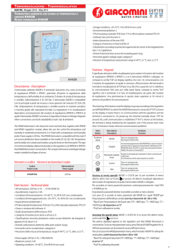
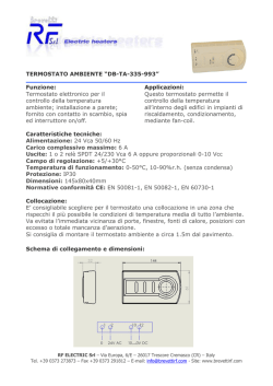
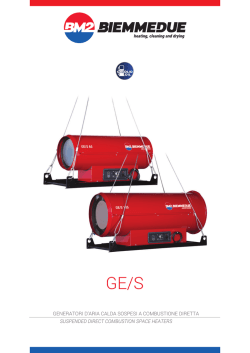
TAE/D
Termostato Ambiente Elettronico
con Display
Manuale d’istruzioni
Introduzione
La ringraziamo per la fiducia che ha voluto riservarci e ci complimentiamo
con Lei per aver scelto un nostro prodotto. Il presente dispositivo è un
termostato elettronico, che consente di regolare la temperatura ambiente
nel luogo in cui è installato; è pertanto in grado di soddisfare le esigenze
degli utenti in termini di comfort ambientale.
cucine,
elettrodomestici
come
televisori, frigoriferi, computer, ecc..),
correnti d’aria (porte, finestre, ventole,
ecc..) e vibrazioni, a circa 1,5m dal
pavimento
garantendo
intorno
all’apparecchio
una
normale
circolazione dell’aria. (fig.1)
Fig. 1
COMANDI DEL
TERMOSTATO
1.
2.
3.
4.
Schema dimensionale senza e con placca
SOSTITUZIONE DELLE BATTERIE
Installazione
senza placca
CONFORMITA’ ALLE
DIRETTIVE
• B.T. 2006/95/CE
• EMC 2004/108CE ed
aggiornamenti successivi
• 93/68/CE
ROHS 2002/95/CE
• EN 60730-1 : 2000
• EN 60730-2-9: 2002
ed aggiornamenti successivi
CONTENUTO DELLA CONFEZIONE
Sono presenti;
• Il termostato TAE/D
• Una coppia pile alkaline 1,5V LR03 (Tipo AAA )
• Placca di adattamento per montaggio su scatola incasso muro:
tonda (ø 60 mm) o quadrata (due moduli)
• Viti e tasselli per fissaggio a muro ed alla placca di adattamento
• Manuale istruzioni
CARATTERISTICHE TECNICHE
Alimentazione: 2 Batterie Alcaline 1,5V LR03 (Tipo AAA )
Campo di visualizzazione temperatura: 0°C÷39°C
Campo di regolazione temperatura: 5°C÷35°C
Tempo di intervento: immediato o con ritardo di 3 minuti
Risoluzione temperatura: 0,1°C in visualizzazione e
1,0°C in impostazione
Differenziale temperatura: 0,4°C.÷0.6°C ÷0.8°C ÷1,0°C
(0,6°C impostazione di fabbrica)
Sonda di temperatura: NTC 10KΩ@25°C
Grado di protezione:IP20
Classe di isolamento: Tipo II (doppio isolamento
)
Uscita: relè in scambio (Tipo SPDT)
Portata sui contatti: 6A(3A)/250VAC 50-60Hz
Tipo di azione: 1B
Situazione di installazione: ambiente normale
Temperatura di stoccaggio: 0÷60°C
Montaggio: a parete con o senza placca di adattamento.
ATTENZIONE!
Si raccomanda di eseguire l’installazione del termostato rispettando
scrupolosamente le norme di sicurezza e le disposizioni di legge vigenti.
POSIZIONAMENTO
La posizione del termostato può influire in modo determinante sulle
prestazioni.
Installare il termostato su una parete interna di un locale in cui si soggiorna
abitualmente, lontano da fonti di calore (caloriferi, raggi solari,
MI070325_REV09_ITA_GB_04/10.doc
All’apparire sul display della scritta Lo
alternativamente al valore di temperatura
ambiente è necessario sostituire le batterie al
più presto possibile.
Per la sostituzione delle batterie rimuovere il
coperchio anteriore usando un cacciavite per
fare pressione sul dentino posto sul lato
superiore (Fig. 3).
SIMBOLI
VISUALIZZABILI
con placca
CONFORMITA’ ALLE
NORME
Display
Pulsante per aumentare la
temperatura.
Interruttore acceso/spento
Pulsante per diminuire la
temperatura.
Temporizzatore d’accensione
Per evitare accensioni e spegnimenti troppo ravvicinati che si possono
presentare in particolari situazioni d’uso, all’interno del termostato è
presente un selettore (fig. 6) che consente di impostare un intervallo
minimo di 3 minuti (ciclo minimo di intervento) tra una attivazione
dell’utilizzatore e la successiva .
L’impostazione di fabbrica di tale selettore, prevede l’attivazione immediata
dell’utilizzatore al raggiungimento della temperatura di intervento (fig. 7).
Dopo aver modificato la posizione del selettore, premere Reset per
rendere attiva la modifica.
ATTENZIONE!
MODO DI FUNZIONAMENTO
Prima di collegare il termostato accertarsi che il carico utilizzatore da
comandare (caldaia, pompa, ecc.) non sia collegato, e che la tensione di
alimentazione corrisponda a quella riportata
all’interno della base dell’apparecchio
(250V~max.). Quindi togliere corrente
all’interruttore generale di rete (fig.2) prima
di effettuare qualsiasi collegamento.
Fig. 2
Premere
l’interruttore
acceso/spento
per
attivare/disattivare
il
funzionamento del Termostato Ambiente. La visualizzazione del display
non cambia nei due stati di funzionamento.
Quando il TAE/D è attivo, l’impianto di riscaldamento viene acceso (con
carico collegato nella modalità RISCALDAMENTO) o l’impianto di
condizionamento viene disattivato (con carico collegato nella modalità
CONDIZIONAMENTO) se la temperatura ambiente scende sotto la
temperatura di comfort impostata (Impostazione di fabbrica = 20°C).
INSTALLAZIONE
Impostazione temperatura di comfort
Durante la sostituzione il termostato mantiene la precedente impostazione
della temperatura di comfort per circa 3 minuti. Per periodi superiori il
termostato riprende il suo funzionamento con le impostazioni di fabbrica.
Si raccomanda di rispettare la polarità indicata. A sostituzione avvenuta
richiudere l’apparecchio assicurandosi di riagganciare la parte inferiore del
coperchio prima di premerlo delicatamente sulla parte superiore fino a
sentire lo scatto del dentino.
SOLUZIONE PROBLEMI
PROBLEMA
L’apparecchio non si
accende
POSSIBILE CAUSA
Batterie scariche
Batterie inserite non
correttamente
Falso contatto
Segnalazione Err
Malfunzionamento
termostato
Batterie scariche
Collegamenti errati
1. Dopo l‘inserimento delle batterie nel termostato, attendere fino alla
visualizzazione fissa del valore della temperatura ambiente rilevata.
Rimuovere il coperchio anteriore usando un
cacciavite per fare pressione sul dentino
posto sul lato superiore (fig.3).
o
e il display visualizzerà il simbolo
, la
2. Premere i tasti
scritta SET e la temperatura di comfort precedentemente impostata.
Separare la base dal coperchio (fig.4).
Fig. 3
Sganciare la protezione che copre i morsetti
elettrici premendola ai lati e tirandola verso
l’esterno.
3. Premere ancora i tasti
lampeggiante.
o
e l’indicazione sul display diventerà
o
la temperatura di
4. Ad ogni pressione successiva dei tasti
comfort diminuirà o incrementerà di 1,0°C.
5. Il valore appena impostato lampeggerà sul display per circa
6 secondi e sarà memorizzato. Il display tornerà in visualizzazione
fissa della temperatura ambiente rilevata
Fissare la base alla parete (con o senza la
placca di adattamento fornita) utilizzando gli
appositi fori (fig.5), ponendo attenzione al
corretto posizionamento dei cavi.
Fig. 4
FUNZIONI SUPPLEMENTARI
Tasto RESET
Collegare i cavi alla morsettiera e inserire le
batterie come indicato nella (fig.6).
Riposizionare la protezione dei morsetti ed il
coperchio.
Fig. 5
Per riportare tutti i parametri dello strumento ai valori impostati in fabbrica
(temperatura Æ 20,0°C, differenziale di temperatura Æ 0,6°C), bisogna
premere il tasto RESET all’interno del termostato (fig. 6).
La buona riuscita dell’operazione viene confermata tramite la
visualizzazione contemporanea per alcuni secondi di tutti i simboli del
display.
SCHEMA COLLEGAMENTI ELETTRICI
ATTENZIONE!
Collegare la FASE al
morsetto 1 (Comune) ed
il carico al morsetto 3.
(U condiz) per utilizzare il
termostato in modalità
CONDIZIONAMENTO
oppure al morsetto 5
(U risc) per utilizzarlo
in modalità
RISCALDAMENTO.
Fig. 6
Segnalazione Lo
Gli impianti di
Riscaldamento o
Condizionamento non
si attivano ma il
simbolo
è visibile (in modalità
Riscaldamento) o
è spento (in modalità
Condizionamento)
Gli impianti di
Riscaldamento o
Condizionamento non
si attivano e il simbolo
NON compare (in
Riscaldamento) o
risulta visibile (in
Condizionamento)
La temperatura
ambiente visualizzata
non corrisponde a
quella reale
L’apparecchio si
comporta in modo
“irregolare”
Fig. 7
Interruttore spento
SOLUZIONE
Sostituire le batterie
Verificare la corretta
polarità
Verificare corretto
inserimento batterie e
premere tasto reset
Premere tasto reset
Sostituire le batterie
Verificare i
collegamenti dei fili
tra utilizzatore e
morsetti del
termostato (Fig.6)
Selezionare
correttamente
l’interruttore
acceso/spento
Premere tasto reset
Malfunzionamento
termostato
Temperatura
Impostare
richiesta inferiore (In
un’adeguata
Riscaldamento) o
temperatura con tasti
superiore (in modalità
o
Condizionamento)
(vedi istruzioni)
alla temperatura
ambiente attuale.
Malfunzionamento
Premere tasto reset
termostato
Errata posizione del
termostato
nell’ambiente
Corrente d’aria
proveniente dal tubo
che porta i fili
dell’impianto al
termostato
Batterie non alkaline
Malfunzionamento
termostato
Seguire le istruzioni
paragrafo
“POSIZIONAMENTO”
Sigillare il condotto
del tubo per evitare
correnti d’aria calda o
fredda
Utilizzare batterie
Alkaline 1,5V LR03
(Tipo AAA )
Premere tasto reset
In caso di anomalie persistenti non manomettere per nessun motivo
alcuna parte del prodotto, ma contattare il proprio tecnico di fiducia o il
punto vendita.
TAE/D
Electronic Room Thermostat
with Display
Instruction Manual
Introduction
Thank you for selecting our product. This electronic thermostat allows you
to adjust the ambient temperature in the room in which it is installed, thus
providing ideal room comfort.
household appliances such as TVs,
refrigerators,
computers,
etc.),
draughts (doors, windows, fans, etc.)
and vibrations, about 1.5m above the
floor in a location which ensures
normal air circulation around the
device (fig.1).
Fig. 1
THERMOSTAT
CONTROLS
5.
6.
7.
8.
Dimensional diagram without and with plate
REPLACING THE BATTERIES
Installation
Without plate
CONFORMITY WITH THE
DIRECTIVES
• L.V. 2006/95/EC
• EMC 2004/108EC and
subsequent amendments
• 93/68/EC
ROHS 2002/95/EC
• EN 60730-1 : 2000
• EN 60730-2-9: 2002
and subsequent amendments
PACKAGE CONTENTS
The package contains:
• The TAE/D thermostat
• A pair of 1.5V LR03 (Type AAA ) alkaline batteries
• Adapter plate for assembly on flush-mounted wall box:
round (ø 60 mm) or square (two modules)
• Screws and plugs for fastening to the wall and adapter plate
• Instruction manual
TECHNICAL SPECIFICATIONS
Power Supply: 2 Alkaline Batteries 1.5V LR03 (Type AAA)
Temperature display range: 0°C÷39°C
Temperature regulation range: 5°C÷35°C
Operate time: immediate or with a 3-minute delay
Temperature resolution: 0.1°C on the display and
1.0°C in setting
Temperature differential: 0.4°C.÷0.6°C ÷0.8°C ÷1.0°C
(factory setting: 0.6°C)
Temperature probe: NTC 10KΩ@25°C
Degree of protection: IP20
Insulation class: Type II (double insulation
)
Output: changeover relay (Type SPDT)
Capacity on the contacts: 6A(3A)/250VAC 50-60Hz
Type of action: 1B
Installation situation: Normal room
Storage temperature: 0÷60°C
Assembly: wall-mounted with or without adapter plate.
CAUTION!
The thermostat must be installed in strict compliance with safety standards
and current regulations.
PLACEMENT OF THE THERMOSTAT
The position of the thermostat may have a decisive impact on its
performance.
Install the thermostat on an internal wall of a room which is normally
occupied, far from sources of heat (heaters, sunlight, kitchens,
MI070325_REV09_ITA_GB_04/10.doc
When the legend Lo appears on the display
alternatively with the value of the room
temperature, the batteries must be replaced
as soon as possible.
To replace the batteries, remove the front
cover using a screwdriver to press on the
small tab located on the top side (Fig. 3).
DISPLAY
SYMBOLS
With plate
CONFORMITY WITH THE
STANDARDS
Display
Button to increase the
temperature
On/Off switch
Button to decrease the
temperature
Turn-on timer
To prevent the equipment from being turned on and off too soon as may
occur under certain usage conditions, a selector inside the thermostat
(fig. 6) can be used to set a minimum interval of 3 minutes (minimum
operating cycle) between one activation of the equipment and the next.
This selector is factory-set for immediate activation of the equipment when
the operating temperature is reached (fig. 7).
After changing the position of the selector, press Reset to make the
modification active.
CAUTION!
OPERATING MODE
Before connecting the thermostat, make certain that the equipment load to
be controlled (boiler, pump, etc.) is not connected and that the power
supply voltage corresponds to the value
shown inside the base of the device (250V~
max.) Then cut off the mains current using
the general switch (fig.2) before making
any connection.
Fig. 2
Press the on/off switch to activate/deactivate operation of the Room
Thermostat. The display remains unchanged in the two operating states.
When the TAE/D is active, the heating system is turned on (with load
connect in HEAT MODE) or the cooling system is turned off (with load
connect in COOL MODE) if the room temperature drops below the comfort
temperature set on it (Factory setting = 20°C).
INSTALLATION
Setting the comfort temperature
7. Press the
or
PROBLEM
The device does not
turn on.
POSSIBLE CAUSE
Low batteries
Batteries inserted
incorrectly
False contact
Err signal
Thermostat
malfunction
Low batteries
Incorrect connections
buttons and the display will show the symbol
, the legend SET and the comfort temperature that was set
previously.
Separate the base from the cover (fig.4).
Fig. 3
Release the protection covering the
electrical terminals by pressing on the sides
and pulling it outwards.
or
8. Press the
begin to flash.
buttons again and the indication on the display will
or
button is pressed, the comfort
9. Now each time the
temperature will decrease or increase by 1.0°C.
10. The value just set will flash on the display for about 6 seconds and be
stored. Then the detected room temperature will return fixed on the
display.
Fix the base to the wall (with or without the
adapter plate supplied) using the
appropriate holes (fig.5), being careful to
position the cables correctly.
Fig. 4
ADDITIONAL FUNCTIONS
RESET button
To return all the instrument parameters to their factory-set values
(temperature Æ 20.0°C, temperature differential Æ 0.6°C), press the
RESET button inside the thermostat (fig. 6).
The successful outcome of this operation is confirmed by the simultaneous
display of all symbols on the display for a few seconds.
Connect the cables to the terminal board
and insert the batteries as indicated in
(fig.6).
of
TROUBLESHOOTING
6. After the batteries have been inserted in the thermostat, wait until the
detected room temperature appears fixed on the display.
Remove the front cover using a screwdriver
to press on the small tab located on the top
side (fig.3).
Replace the plastic protection
terminals and the cover.
During replacement, the thermostat maintains
the previous comfort temperature setting for about 3 minutes. For longer
periods, the thermostat resumes operation with the factory settings. Insert
the new batteries according to the polarity indicated. After the new
batteries have been inserted, close the device by hooking on the lower
part of the cover and then pressing the top part on gently until hearing the
small tab click.
the
Fig. 5
symbol appears
(in Heat mode) or
Switch off
does not appear (in
Cool mode)
Thermostat
malfunction
The Heat or Cool
Required temperature
systems does not turn less (in Heat mode) or
on and the
upper (in Cool mode)
than the actual room
temperature
symbol does
NOT appear (in Heat Thermostat
malfunction
mode) or appear (in
Cool mode)
The room temperature Incorrect positioning
displayed does not
of the thermostat in
correspond to the real the room
temperature
Draught coming from
the cable duct that
conveys the system
wires to the
thermostat
The device behaves in Non-alkaline batteries
an "irregular” manner
ELECTRICAL CONNECTION DIAGRAM
CAUTION!
Connect the LINE to
terminal 1 (Common) and
the load to terminal 3
(L cool) to use the
thermostat in COOL
MODE
or to terminal 5 (L heat) to
use it in HEAT MODE.
Fig. 6
Lo signal
The Heat or Cool
systems does not turn
on and the
Thermostat
malfunction
Fig. 7
SOLUTION
Replace the batteries
Check that the polarity
is correct
Check that the
batteries are inserted
correctly and press
the reset button
Press the reset button
Replace the batteries
Check the
connections of the
wires between the
equipment and the
thermostat terminals
(Fig.6)
Set the On/Off
selector correctly
Press the reset button
Set a suitable
temperature using the
or
buttons
(see instructions)
Press the reset button
Follow the instructions
provided in the
“POSITIONING”
section
Seal the duct in order
to avoid warm or cool
draughts
Use alkaline batteries
1.5V LR03
(AAA Type)
Press the reset button
Problems continue, do not tamper with any part of the product for any
reason whatsoever, but contact your technician or local sales outlet.
© Copyright 2026 Paperzz