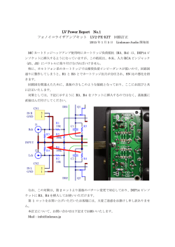
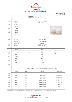
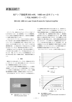
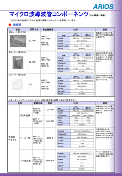
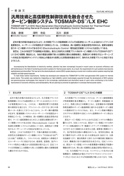
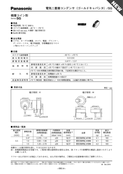
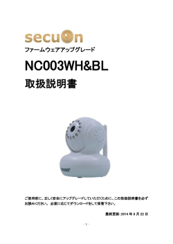
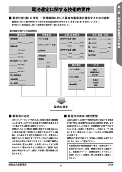
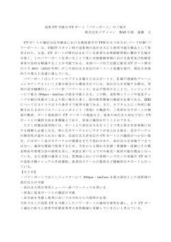
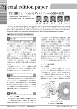
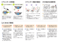
GETTING STARTED GUIDE
NI PXI-4110
Triple-Output Programmable DC Power Supply
Note Before you begin, install and configure your chassis and controller.
This document explains how to install, configure, and test the NI PXI-4110 (NI 4110). The
NI 4110 is a triple-output programmable DC power supply.
To access NI 4110 documentation, navigate to Start»All Programs»National Instruments»
NI-DCPower»Documentation.
Contents
Electromagnetic Compatibility Guidelines............................................................................... 1
Verifying the System Requirements..........................................................................................2
Safety........................................................................................................................................ 2
Unpacking the Kit..................................................................................................................... 2
Kit Contents.............................................................................................................................. 3
Other Equipment............................................................................................................... 4
Preparing the Environment....................................................................................................... 4
Installing the Software.............................................................................................................. 4
Installing the NI 4110................................................................................................................5
Configuring the NI 4110 in MAX.............................................................................................7
Programming the NI 4110.........................................................................................................8
Troubleshooting........................................................................................................................ 8
What Should I Do if the NI 4110 Doesn't Appear in MAX?............................................ 8
What Should I Do if the Module Fails the Self-Test?.......................................................9
Where To Go Next.................................................................................................................. 10
Worldwide Support and Services............................................................................................ 10
Electromagnetic Compatibility Guidelines
This product was tested and complies with the regulatory requirements and limits for
electromagnetic compatibility (EMC) stated in the product specifications. These requirements
and limits provide reasonable protection against harmful interference when the product is
operated in the intended operational electromagnetic environment.
This product is intended for use in industrial locations. However, harmful interference may
occur in some installations, when the product is connected to a peripheral device or test object,
or if the product is used in residential or commercial areas. To minimize interference with
radio and television reception and prevent unacceptable performance degradation, install and
use this product in strict accordance with the instructions in the product documentation.
Furthermore, any changes or modifications to the product not expressly approved by National
Instruments could void your authority to operate it under your local regulatory rules.
Caution To ensure the specified EMC performance, operate this product only with
shielded cables and accessories.
Caution To ensure the specified EMC performance, the length of all attached
cables must be no longer than 30 m (100 ft). In addition, the cable or cables
connected to the Output port must be provided with an overall shield that is
terminated to pin 2 ( ).
Verifying the System Requirements
To use the NI-DCPower instrument driver, your system must meet certain requirements.
For more information about minimum system requirements, recommended system, and
supported application development environments (ADEs), refer to the product readme, which
is available on the driver software media or online at ni.com/updates.
Safety
Caution Always refer to the specifications document included with the NI 4110
device before connecting signals. Failure to observe the specified maximum signal
ratings can cause shock, a fire hazard, or damage to the devices connected to the
NI 4110. NI is not liable for any damage or injuries resulting from incorrect signal
connections.
Related Information
For information about connecting signals for specific devices, refer to the NI DC Power
Supplies and SMUs Help.
Unpacking the Kit
Caution To prevent electrostatic discharge (ESD) from damaging the device,
ground yourself using a grounding strap or by holding a grounded object, such as
your computer chassis.
Touch the antistatic package to a metal part of the computer chassis.
1.
2.
Remove the device from the package and inspect the device for loose components or any
other sign of damage.
Caution Never touch the exposed pins of connectors.
2
|
ni.com |
NI PXI-4110 Getting Started Guide
Notify NI if the device appears damaged in any way. Do not install a damaged device.
3.
Unpack any other items and documentation from the kit.
Store the device in the antistatic package when the device is not in use.
Kit Contents
Figure 1. NI 4110 Kit Contents
1
4
7
1.
2.
3.
4.
8
NI PXI-4110 Power Supply
6-position MINI-COMBICON Connector
2-position MINI-COMBICON Connector
Backshell for 6-position MINI-COMBICON
Connector
5. Backshell for 2-position MINI-COMBICON
Connector
2
3
5
6
9
10
6. (Optional) Auxiliary 12 V Power Source
7. Driver Software DVD
8. NI PXI-4110 Getting Started Guide (this
document)
9. Read Me First: Safety and Electromagnetic
Compatibility
10. Maintain Forced-Air Cooling Note to Users
NI PXI-4110 Getting Started Guide |
© National Instruments
|
3
Other Equipment
There are several required items not included in your device kit that you need to operate the
NI 4110. Your application may require additional items not included in your kit to install or
operate your device.
Required Items
•
A PXI or PXI Express hybrid chassis and chassis documentation. For more information
about compatible chassis options, refer to ni.com.
A PXI embedded controller or MXI controller system that meets the system requirements
specified in this guide and chassis documentation.
1/8 in. flathead screwdriver
•
•
Optional Item
•
If you choose to connect an optional auxiliary 12 V power source to the device, you must
either purchase an NI APS-4100 auxiliary power source from NI (part number
779671-01) or use an auxiliary power source from a third-party vendor.
Related Information
Installing the NI 4110 on page 5
Preparing the Environment
Ensure that the environment you are using the NI 4110 in meets the following specifications.
Operating Environment
Ambient
....................................................................
temperature range
0 °C to 55 °C (Tested in accordance with
IEC 60068-2-1 and IEC 60068-2-2.)
Relative
....................................................................
humidity range
10% to 90%, noncondensing (Tested in
accordance with IEC 60068-2-56.)
Maximum altitude
............................................................................
2,000 m (at 25 °C ambient temperature)
Pollution Degree
............................................................................
2
Indoor use only.
Note Refer to the device specifications on ni.com/manuals for complete
specifications.
Installing the Software
You must be an Administrator to install NI software on your computer.
1. Install an ADE, such as LabVIEW or LabWindows™/CVI™.
4
|
ni.com |
NI PXI-4110 Getting Started Guide
2.
Insert the driver software media into your computer. The installer should open
automatically.
If the installation window does not appear, navigate to the drive, double-click it, and
double-click autorun.exe.
3.
Follow the instructions in the installation prompts.
Note Windows users may see access and security messages during
installation. Accept the prompts to complete the installation.
4.
When the installer completes, select Restart in the dialog box that prompts you to restart,
shut down, or restart later.
Installing the NI 4110
Caution To prevent damage to the device caused by ESD or contamination, handle
1.
the device using the edges or the metal bracket.
Ensure the AC power source is connected to the chassis before installing the modules.
The AC power cord grounds the chassis and protects it from electrical damage while you
install the modules.
2.
Power off the chassis.
3.
Inspect the slot pins on the chassis backplane for any bends or damage prior to
installation. Do not install a module if the backplane is damaged.
4.
Remove the black plastic connectors from all the captive screws on the module front
panel.
5.
Identify a supported slot in the chassis. The following figure shows the symbols that
indicate the slot types.
Figure 2. Chassis Compatibility Symbols
NI PXIe-1062Q
1
1. PXI Express System Controller Slot
2. PXI Peripheral Slot
3. PXI Express Hybrid Peripheral Slot
2
3
5
4
4. PXI Express System Timing Slot
5. PXI Express Peripheral Slot
NI 4110 modules can be placed in PXI peripheral slots or PXI Express Hybrid peripheral
slots.
6.
Touch any metal part of the chassis to discharge static electricity.
7.
Ensure that the ejector handle is in the unlatched (downward) position.
8.
Place the module edges into the module guides at the top and bottom of the chassis. Slide
the device into the slot until it is fully inserted.
NI PXI-4110 Getting Started Guide |
© National Instruments
|
5
Figure 3. Module Installation
1
NI
PX
Ie
-10
75
2
3
1. Chassis
2. Hardware Module
3. Ejector Handle in Down (Unlatched) Position
9.
Latch the module in place by pulling up on the ejector handle.
10. Secure the device front panel to the chassis using the front-panel mounting screws.
Note Tightening the top and bottom mounting screws increases mechanical
stability and also electrically connects the front panel to the chassis, which can
improve the signal quality and electromagnetic performance.
11. Cover all empty slots using filler panels or slot blockers to maximize cooling air flow.
12. (Optional) To gain full output power of the isolated channels on the NI 4110, connect an
auxiliary 12 V power source to the auxiliary power input connector of the device. Tighten
the screws to hold the auxiliary 12 V power source in place.
Note The NI 4110 automatically uses the optional auxiliary 12 V power
source, if it is available, when the session is opened. To override this feature,
use the Power Source property or the NIDCPOWER_ATTR_POWER_SOURCE
attribute.
Figure 4. Connecting an Optional Auxiliary 12 V Power Source
+
1
–
1. Optional Auxiliary Power Source
6
|
ni.com |
NI PXI-4110 Getting Started Guide
Note The auxiliary power source provided by NI uses sufficient wire gauge to
maintain voltage requirements for the device. If you use a third-party auxiliary
power source, you must use the appropriate wire gauge to ensure that it can
provide the required device current without dropping below the minimum
voltage at the auxiliary power input connector.
13. Power on the chassis.
Related Information
For information about wire gauge, refer to the NI DC Power Supplies and SMUs Help.
For internal and auxiliary power ratings, refer to the specifications for your device.
For more information about using an optional auxiliary 12 V power source with your device,
refer to the Internal and Auxiliary Power topic in the NI DC Power Supplies and SMUs Help.
Configuring the NI 4110 in MAX
Use Measurement & Automation Explorer (MAX) to configure your National Instruments
hardware. MAX informs other programs about which devices reside in the system and how
they are configured. MAX is automatically installed with NI-DCPower.
1. Launch MAX.
2.
In the configuration tree, double-click Devices and Interfaces to see the list of installed
devices.
3.
Expand your Chassis tree item.
Installed devices appear under the name of their associated chassis.
MAX lists all devices installed in the chassis. Your default device names may vary.
Note If you do not see your device listed, press <F5> to refresh the list of
installed devices. If the device is still not listed, power off the system, ensure
the device is correctly installed, and restart.
4.
Record the device identifier MAX assigns to the hardware. Use this identifier when
programming the NI 4110.
5.
Self-test the device by selecting the device in the configuration tree and clicking Self-Test
in the MAX toolbar.
The MAX self-test performs a basic verification of hardware resources.
NI PXI-4110 Getting Started Guide |
© National Instruments
|
7
Programming the NI 4110
You can generate signals interactively using the NI-DCPower Soft Front Panel (SFP) or you
can use the NI-DCPower instrument driver to program your device in the supported ADE of
your choice.
Table 1. NI 4110 Programming Options
Application
Programming
Interface (API)
Location
Description
NI-DCPower SFP
Available from the start
menu at Start»All
Programs»National
Instruments»NI-DCPower»
NI-DCPower Soft Front
Panel.
The NI-DCPower SFP acquires,
controls, and presents data. The
NI-DCPower SFP operates on the
PC, to provide additional display
capabilities.
NI-DCPower
Instrument Driver
LabVIEW—Available on the
LabVIEW Functions palette
at Measurement I/O»NIDCPower.
NI-DCPower configures and operates
the device hardware and performs
basic acquisition and measurement
options using LabVIEW VIs or
LabWindows/CVI functions.
C or LabWindows/CVI—
Available at Program Files»
IVI Foundation»IVI»
Drivers»NI-DCPower.
Microsoft Visual C/C++—
NI-DCPower does not ship
with installed C/C++
examples.
Refer to the Creating an Application
with Microsoft Visual C and C++
topic of the NI DC Power Supplies
and SMUs Help to manually add all
required include and library files to
your project.
Troubleshooting
If an issue persists after you complete a troubleshooting procedure, contact NI technical
support or visit ni.com/support.
What Should I Do if the NI 4110 Doesn't Appear in
MAX?
1.
In the MAX configuration tree, click Devices and Interfaces.
2.
Expand the Chassis tree to see the list of installed devices, and press <F5> to refresh the
list.
8
|
ni.com |
NI PXI-4110 Getting Started Guide
3.
If the module is still not listed, power off the system, ensure that all hardware is correctly
installed, and restart the system.
4.
Navigate to the Device Manager.
Operating System Description
5.
Windows 8
Right-click the Start screen, and select All apps»Control Panel»
Hardware and Sound»Device Manager.
Windows 7
Select Start»Control Panel»Device Manager.
Windows Vista
Select Start»Control Panel»System and Maintenance»Device
Manager.
Windows XP
Select Start»Control Panel»System»Hardware»Device
Manager.
If you are using a PXI controller, verify that a National Instruments entry appears in the
system device list. Reinstall NI-DCPower and the device if error conditions appear in the
list. If you are using an MXI controller, right-click PCI-to-PCI Bridge, and select
Properties from the shortcut menu to verify that the bridge is enabled.
What Should I Do if the Module Fails the Self-Test?
1.
Restart the system.
2.
Launch MAX, and perform the self-test again.
3.
Power off the chassis.
4.
Reinstall the failed module in a different slot.
5.
Power on the chassis.
6.
Perform the self-test again.
NI PXI-4110 Getting Started Guide |
© National Instruments
|
9
Where To Go Next
Located in the hardware kit
Located online at ni.com/manuals
Located using the NI Example Finder
EXPLORE
LEARN
CREATE
the application
development environment (ADE)
for your application.
about hardware features
or review device
specifications.
custom applications within
an application programming
interface (API).
NI PXIe-4112
Learn LabVIEW Basics
NI PXI 4110 Specifications*
NI-DCPower Soft Front Panel
NI-DCPower Instrument Driver
NI DCPower Examples*
Getting Started with
LabWindows/CVI
NI DC Power Supplies
and SMUs Help*
NI DC Power Supplies
and SMUs Help*
DISCOVER
more about your products through ni.com.
Support
ni.com/support
Power Supplies
Solutions
ni.com/powersupplies
Services
ni.com/services
NI Community
ni.com/community
*This item is also installed with the driver software.
Worldwide Support and Services
The National Instruments website is your complete resource for technical support. At ni.com/
support, you have access to everything from troubleshooting and application development
self-help resources to email and phone assistance from NI Application Engineers.
Visit ni.com/services for NI Factory Installation Services, repairs, extended warranty, and
other services.
Visit ni.com/register to register your National Instruments product. Product registration
facilitates technical support and ensures that you receive important information updates from
NI.
A Declaration of Conformity (DoC) is our claim of compliance with the Council of the
European Communities using the manufacturer’s declaration of conformity. This system
affords the user protection for electromagnetic compatibility (EMC) and product safety. You
10
|
ni.com
|
NI PXI-4110 Getting Started Guide
can obtain the DoC for your product by visiting ni.com/certification. If your product supports
calibration, you can obtain the calibration certificate for your product at ni.com/calibration.
National Instruments corporate headquarters is located at 11500 North Mopac Expressway,
Austin, Texas, 78759-3504. National Instruments also has offices located around the world.
For telephone support in the United States, create your service request at ni.com/support or
dial 1 866 ASK MYNI (275 6964). For telephone support outside the United States, visit the
Worldwide Offices section of ni.com/niglobal to access the branch office websites, which
provide up-to-date contact information, support phone numbers, email addresses, and current
events.
NI PXI-4110 Getting Started Guide |
© National Instruments
|
11
Refer to the NI Trademarks and Logo Guidelines at ni.com/trademarks for information on National Instruments trademarks.
Other product and company names mentioned herein are trademarks or trade names of their respective companies. For patents
covering National Instruments products/technology, refer to the appropriate location: Help»Patents in your software, the
patents.txt file on your media, or the National Instruments Patent Notice at ni.com/patents. You can find information about
end-user license agreements (EULAs) and third-party legal notices in the readme file for your NI product. Refer to the Export
Compliance Information at ni.com/legal/export-compliance for the National Instruments global trade compliance policy and
how to obtain relevant HTS codes, ECCNs, and other import/export data. NI MAKES NO EXPRESS OR IMPLIED WARRANTIES
AS TO THE ACCURACY OF THE INFORMATION CONTAINED HEREIN AND SHALL NOT BE LIABLE FOR ANY ERRORS.
U.S. Government Customers: The data contained in this manual was developed at private expense and is subject to the
applicable limited rights and restricted data rights as set forth in FAR 52.227-14, DFAR 252.227-7014, and DFAR 252.227-7015.
© 2015 National Instruments. All rights reserved.
374793A-01
Feb15
スタートアップガイド
NI PXI-4110
トリプル出力プログラマブル DC 電源
メモ 作業を開始する前に、シャーシおよびコントローラを取り付けて構成
します。
このドキュメントでは、NI PXI-4110(NI 4110)の取り付け、構成、およびテスト方法に
ついて説明しています。 NI 4110 は、トリプル出力プログラマブル DC 電源です。
NI 4110 のドキュメントにアクセスするには、スタート→すべてのプログラム→
National Instruments→NI-DCPower→ドキュメントを参照してください。
目次
電磁両立性ガイドライン.................................................................................................................................. 1
システム要件を確認する.................................................................................................................................. 2
安全性........................................................................................................................................................................... 2
キットを梱包から取り出す............................................................................................................................. 3
キットに含まれる部品........................................................................................................................................4
他の装置............................................................................................................................................................5
環境を整える............................................................................................................................................................5
ソフトウェアをインストールする.............................................................................................................. 6
NI 4110 を取り付ける............................................................................................................................................6
NI 4110 を MAX で構成する...............................................................................................................................8
NI 4110 をプログラムする............................................................................................................................... 10
トラブルシューティング.................................................................................................................................11
MAX で NI 4110 が表示されない場合...............................................................................................11
モジュールがセルフテストで不合格になる..............................................................................11
その他のガイドとヘルプ................................................................................................................................ 12
世界各地でのサポートおよびサービス..................................................................................................12
電磁両立性ガイドライン
この製品は、製品仕様書に記載された電磁両立性(EMC)の規制基準および制限に基
づいて所定の試験が実施され、これらに適合するものと認定されています。 これらの
基準および制限は、製品を意図された動作電磁環境で操作する場合に、有害な電磁妨
害から保護するために設けられました。
この製品は、工場での使用を意図して設計されています。 ただし、この製品が周辺デ
バイスまたは試験対象に接続されている場合、または住宅地域もしくは商業地域で使
用されている場合、設置方法によっては有害な電磁妨害が発生する場合があります。
製品によるラジオおよびテレビ受信への電磁妨害、そして許容できない性能低下を最
小限に抑えるには、製品ドキュメントの手順に厳密に従って取り付け、使用してくだ
さい。
また、ナショナルインスツルメンツによって明示的に許可されていない製品への変更
および修正は、地域の取締規則下で製品を操作するユーザの権利を無効にする可能性
があります。
注意 指定された EMC のパフォーマンスを確保するには、シールドケーブル
およびアクセサリを必ず使用してください。
注意 また、すべての接続されたケーブルも 30 m
(100 ft)未満である必要があります。また、出力ポートに接続されたケーブル
は、ピン 2 に終端されるシールドを備えている必要があります( )。
システム要件を確認する
NI-DCPower 計測器ドライバを使用するには、特定の要件を満たすシステムが必要で
す。
最低システム要件、推奨要件、サポートされている開発環境(ADE)については、ド
ライバソフトウェアメディアに含まれる、または ni.com/updates から入手できる製品
の readme を参照してください。
安全性
注意 信号を接続する際は、必ず事前に NI 4110 デバイスの仕様書を参照して
ください。仕様書に記載されている最大定格の確認を怠った場合、NI 4110 に
接続されているデバイスにおいてショック、発火、その他の破損が起こる恐
れがあります。ナショナルインスツルメンツでは、誤った信号接続による破
損や損傷の責任を負いかねます。
関連リンク
特定デバイスの信号接続については、『NI DC 電源および SMU ヘルプ』を参照してく
ださい。
2
|
ni.com |
NI PXI-4110 スタートアップガイド
キットを梱包から取り出す
1.
2.
注意 デバイスに破損をもたらす静電気放電(ESD)を防ぐために、接地スト
ラップを使用したり、コンピュータシャーシなどの接地された物体に触れて、
身体の静電気を逃がしてください。
静電気防止用パッケージをコンピュータシャーシの金属部分に接触させます。
デバイスを箱から取り出し、部品がゆるんでいないかどうか、またはその他の破
損箇所がないかどうかを調べます。
注意 露出しているコネクタピンには絶対に触れないでください。
デバイスが破損している場合は、ナショナルインスツルメンツまでご連絡くださ
い。損傷したデバイスは絶対に使用しないでください。
3.
その他の品目および付属文書をキットから取り出します。
デバイスを使用しないときは、静電気防止用パッケージに入れて保管してください。
NI PXI-4110 スタートアップガイド
|
© National Instruments
|
3
キットに含まれる部品
図 1. NI 4110 キットに含まれる部品
1
4
7
8
1. NI PXI-4110 電源
2. 6 ピン MINI-COMBICON コネクタ
3. 2 ピン MINI-COMBICON コネクタ
4. 6 ピン MINI-COMBICON コネクタ用バックシェル
5. 2 ピン MINI-COMBICON コネクタ用バックシェル
4
|
ni.com |
NI PXI-4110 スタートアップガイド
2
3
5
6
9
10
6. (オプション)12 V 補助電源
ドライバソフトウェア DVD
8. 『NI PXI-4110 スタートアップガイド』(本書)
9. 『はじめにお読みください: 安全対策と電磁両立性
について』
10.『強制空冷の維持について』
7.
他の装置
デバイスキットに含まれていませんが、NI 4110 の操作に必要な装置がいくつかありま
す。デバイスを取り付けまたは操作するために、アプリケーションでキットに含まれ
ていない追加装置が必要な場合があります。
必要部品
•
PXI または PXI Express ハイブリッドシャーシおよびシャーシのドキュメント。対
•
•
応シャーシのオプションについては、ni.com を参照してください。
このガイドおよびシャーシドキュメントで指定されたシステム要件を満たす PXI
組込コントローラまたは MXI コントローラシステム。
1/8 in. マイナスドライバー
オプション部品
•
デバイスにオプションの 12 V 補助電源を接続する場合は、NI から NI APS-4100 補
助電源(製品番号 779671-01)を購入するか、他社製の補助電源を使用する必要が
あります。
関連リンク
NI 4110 を取り付ける 6 ページ
環境を整える
NI 4110 を使用する環境が以下の仕様を満たしていることを確認します。
動作環境
......................................................................................
周囲温度範囲
0 ℃~55 ℃(IEC60068-2-1 および
IEC60068-2-2 に準拠して試験済み。)
......................................................................................
相対湿度範囲
10~90%、結露なきこと(IEC60068-2-56 に
従って試験済み。)
................................................................................................
最大使用高度
2,000 m(周囲温度 25℃時)
................................................................................................
2
汚染度
室内使用のみ。
メモ 完全仕様については、ni.com/manuals からデバイスの仕様を参照して
ください。
NI PXI-4110 スタートアップガイド |
© National Instruments
|
5
ソフトウェアをインストールする
NI のソフトウェアをコンピュータにインストールするには、管理者権限を持っている
必要があります。
1. LabVIEW または LabWindows™/CVI™ などの ADE をインストールします。
ドライバソフトウェアメディアをコンピュータに挿入します。インストーラが自
動的に起動します。
2.
インストールウィンドウが開かない場合は、ドライブを開き、ドライブをダブル
クリックして、autorun.exe をダブルクリックします。
インストール画面の指示に従います。
3.
メモ Windows ではアクセス/セキュリティメッセージが表示される場
合があります。画面の指示に従って、インストールを完了します。
インストールが完了したら、再起動、シャットダウン、または後で再起動するか
どうかを尋ねるダイアログボックスで再起動を選択します。
4.
NI 4110 を取り付ける
注意 ESD や汚れによる破損を避けるために、デバイスを取り扱う際には、
デバイスの端や金属ブラケット部分以外には触れないでください。
モジュールを取り付ける前に、AC 電源がシャーシに接続されていることを確認
します。
1.
モジュールを取り付けている間に、AC 電源コードがシャーシを接地して、シャー
シを電気的破損から保護します。
2.
シャーシの電源を切断します。
3.
取り付け前に、シャーシバックプレーン上のスロットを検査して曲がったピンや
破損しているピンがないかどうか調べます。バックプレーンに損傷がある場合、
モジュールを挿入しないでください。
4.
モジュールのフロントパネルにあるすべての取り付けネジから黒色のゴム製ネジ
カバーを取り外します。
5.
シャーシでサポートされているスロットを特定します。次の図は、スロットタイ
プを表す記号を示しています。
6
|
ni.com |
NI PXI-4110 スタートアップガイド
図 2. シャーシ互換性記号
NI PXIe-1062Q
1
2
1. PXI Express システムコントローラスロット
2. PXI 周辺スロット
4
3
5
4. PXI Express システムタイミングスロット
5. PXI Express 周辺スロット
3. PXI Express ハイブリッド周辺スロット
NI 4110 モジュールは、PXI 周辺スロットまたは PXI Express ハイブリッド周辺ス
ロットに取り付けることができます。
6.
静電気を放電するため、シャーシの金属部分に触れます。
7.
着脱ハンドルがラッチされていない状態(下向き)になっていることを確認しま
す。
8.
モジュールの縁をシャーシの上下にあるモジュールガイドに配置します。デバイ
スがスロットに完全に挿入されるまで押し込みます。
図 3. モジュールの取り付け
1
NI
PX
Ie
-10
75
2
3
1. シャーシ
2. ハードウェアモジュール
3. 脱着ハンドル(下向き、ラッチされていない状態)
脱着ハンドルを引き上げてモジュールを固定します。
10. デバイスのフロントパネルを、シャーシのフロントパネルのマウントレールにネ
ジで固定します。
9.
メモ 上下の取り付けネジを締めることで機械的機構が安定し、またフ
ロントパネルとシャーシも電気的に接続します。これにより信号整合性
と電磁性能が向上します。
NI PXI-4110 スタートアップガイド
|
© National Instruments
|
7
11. フィラーパネルまたはスロットブロッカーですべての空のスロットを塞いで、冷
却のための通気を最大限に確保します。
12. (オプション)NI 4110 の絶縁チャンネルの全出力を得るには、12 V 補助電源をデ
バイスの補助電源入力コネクタに接続します。12 V 補助電源を固定するネジを
締めます。
メモ セッションが開かれているときにオプションの 12 V 補助電源ソー
スが利用可能である場合、NI 4110 は、自動的にその補助電源ソースを使
用します。この機能を無効にするには、
「補助電源」プロパティまたは
「NIDCPOWER_ATTR_POWER_SOURCE」属性を使用します。
図 4. オプションの 12 V 補助電源を接続する
+
1
–
1. オプションの補助電源
メモ NI が提供する補助電源は、適切なワイヤゲージを使用してデバイ
スの要求電圧を保持しています。他社製の補助電源を使用する場合は、
適切なワイヤゲージを使用して補助電源入力コネクタで最小電圧を下回
ることなくデバイスに必要な電流を提供できるようにしてください。
13. シャーシの電源を投入します。
関連リンク
線番については、『NI DC 電源および SMU ヘルプ』を参照してください。
内部および補助電力定格については、デバイスの仕様を参照してください。
デバイスでオプションの 12 V 補助電源を使用する方法については、『NI DC 電源およ
び SMU ヘルプ』を参照してください。
NI 4110 を MAX で構成する
Measurement & Automation Explorer(MAX)を使用すると、お使いの NI ハードウェア
を構成できます。MAX はデバイスがシステムにどのように接続し、構成されているか
についての情報を他のプログラムに通知します。MAX は NI-DCPower のインストール
時に自動的にインストールされます。
1. MAX を起動します。
2. 取り付けられているデバイスのリストを表示するには、ツリー構図でデバイスと
インタフェースをダブルクリックします。
取り付けられているデバイスが関連するシャーシ名の下に表示されます。
8
|
ni.com |
NI PXI-4110 スタートアップガイド
3.
お使いのシャーシのツリー項目を展開します。
MAX はシャーシの下にすべての使用可能なデバイスのリストを表示します。デ
フォルトのデバイス名は使用状況により異なります。
メモ お使いのデバイスがリストに表示されない場合、<F5>を押して取
り付けられているデバイスのリストを更新します。上記の手順を行って
もデバイスが表示されない場合は、システムの電源を切り、デバイスが
適切に取り付けられているか確認した後、再度電源を投入します。
4.
MAX によってハードウェアに割り当てられたデバイス識別子をメモします。
NI 4110 をプログラミングする際に、この識別子を使用します。
5.
構成ツリーでデバイスを選択し、MAX ツールバーのセルフテストをクリックして
セルフテストを実行します。
MAX のセルフテストでは、ハードウェアリソースの基本的確認を行います。
NI PXI-4110 スタートアップガイド |
© National Instruments
|
9
NI 4110 をプログラムする
NI-DCPower ソフトフロントパネル(SFP)を使用して信号を対話的に生成できます。
または、NI-DCPower 計測器ドライバを使用して選択した ADE でデバイスをプログラ
ムすることもできます。
表 1. NI 4110 プログラミングオプション
アプリケーションプ
ログラミングインタ
フェース(API)
場所
説明
NI-DCPower SFP
スタートメニューのス
タート→すべてのプログ
ラム→National
Instruments→NI-DCPower
→NI-DCPower ソフトフ
ロントパネルから使用可
能。
NI-DCPower SFP はデータを集録、制
御、表示します。NI-DCPower SFP は
PC 上で動作するので、追加の表示
機能を使用できます。
NI-DCPower 計測器
ドライバ
LabVIEW―LabVIEW 関数 NI-DCPower はデバイスハードウェ
パレットの測定 I/O→NI- アを構成および操作し、LabVIEW VI
DCPower からアクセス。 または LabWindows/CVI 関数を使
用して基本的集録および集録オプ
C または
ションを実行します。
LabWindows/CVI―すべ
てのプログラム→IVI
Foundation→IVI→ドライ
バ→NI-DCPower からア
クセス。
Microsoft Visual C/C++―
発送時の NI-DCPower に
は C/C++サンプルは含ま
れません。
10
|
ni.com
|
NI PXI-4110 スタートアップガイド
すべての必要なインクルードファ
イルおよびライブラリファイルを
手作業でプロジェクトに追加する
場合は、『NI DC 電源および SMU ヘ
ルプ』の「Microsoft Visual C および
C++でアプリケーションを作成す
る」トピックを参照してください。
トラブルシューティング
トラブルシューティングの手順を実行した後も問題が解決しない場合は、NI の技術サ
ポートまでお問い合わせいただくか、ウェブサイト ni.com/support を参照してくださ
い。
MAX で NI 4110 が表示されない場合
1.
MAX のツリー構図で、デバイスとインタフェースをクリックします。
2.
取り付けられているデバイスのリストを表示するには、シャーシツリーを展開し、
<F5>を押してリストを更新します。
3.
リストを更新してもいずれのモジュールも表示されない場合は、システムの電源
を切り、すべてのハードウェアが正しく取り付けられていることを確認し、シス
テムを再起動します。
4.
デバイスマネージャに移動します。
5.
オペレーティング
システム
説明
Windows 8
スタート画面を右クリックし、すべてのアプリ→コント
ロールパネル→ハードウェアとサウンド→デバイスマネー
ジャを選択します。
Windows 7
スタート →コントロールパネル →デバイスマネージャ を
選択します。
Windows Vista
スタート →コントロールパネル →システムとメンテナン
ス →デバイスマネージャ を選択します。
Windows XP
スタート →コントロールパネル →システム →ハードウェ
ア →デバイスマネージャ を選択します。
PXI コントローラをお使いの場合、National Instruments の項目がシステムデバイ
スのリストに表示されていることを確認します。エラー状態がリストに表示され
ているときは、NI-DCPower の再インストールとデバイスの再取り付けを行いま
す。MXI コントローラをお使いの場合、PCI-to-PCI Bridge を右クリックし、ショー
トカットメニューからプロパティを選択して、ブリッジが有効になっていること
を確認します。
モジュールがセルフテストで不合格になる
1.
コンピュータを再起動します。
2.
MAX を起動し、再度セルフテストを実行します。
3.
シャーシの電源を切断します。
4.
不合格になったモジュールを異なるスロットに再取り付けします。
5.
シャーシの電源を投入します。
NI PXI-4110 スタートアップガイド |
© National Instruments
|
11
再度セルフテストを実行します。
6.
その他のガイドとヘルプ
ハードウェアキットから
NIサンプルファインダから
オンラインでni.com/manualsから
探す
学ぶ
作る
用途に適したアプリケーション
開発環境 (ADE)
デバイス仕様を基にした
ハードウェア機能
アプリケーションプログラミング
インタフェース(API)を使用した
カスタムアプリケーション
NI PXIe-4112
NI-DCPowerソフトフロントパネル
NI-DCPower計測器ドライバ
LabVIEWの基本を学ぶ
NI PXIe 4110仕様*
Getting Started with
LabWindows/CVI
NI DC電源およびSMUヘルプ*
NI DCPowerサンプル*
NI DC電源および
SMUヘルプ*
調べる
ni.comから最新の情報を入手
サポート
ni.com/support
電源およびSMU
ni.com/powersupplies
製品サービス
ni.com/jp/services
NI コミュニティ
ni.com/community/ja
*ドライバソフトウェアと一緒にインストールされる
世界各地でのサポートおよびサービス
技術サポートリソースの一覧は、ナショナルインスツルメンツのウェブサイトでご覧
いただけます。 ni.com/jp/support では、トラブルシューティングやアプリケーション
開発のセルフヘルプリソースから、ナショナルインスツルメンツのアプリケーション
エンジニアの E メール/電話の連絡先まで、あらゆるリソースを参照できます。
ni.com/jp/services からは、NI インストールサービス、修理、保証期間延長、その他の
サービスをご利用いただけます。
ナショナルインスツルメンツ製品は、ni.com/register で登録できます。 製品を登録す
ると、技術サポートをより簡単に受けることができ、NI から重要な最新情報を確実に
受けることができます。
12
|
ni.com
|
NI PXI-4110 スタートアップガイド
適合宣言(Doc)とは、その会社の自己適合宣言を用いた、さまざまな欧州閣僚理事
会指令への適合の宣言のことです。 この制度により、電磁両立性(EMC)に対するユー
ザ保護や製品の安全性に関する情報が提供されます。 ご使用の製品の適合宣言は、
ni.com/certification(英語)から入手できます。 ご使用の製品でキャリブレーション
がサポートされている場合、ni.com/calibration からその製品の Calibration Certificate
(英語)を入手してご利用になることもできます。
ナショナルインスツルメンツでは、米国本社(11500 North Mopac Expressway, Austin,
Texas, 78759-3504)および各国の現地オフィスにてお客様にサポートを提供していま
す。 日本国内でのサポートについては、ni.com/support でサポートリクエストを作成
するか、0120-527196(フリーダイヤル)または 03-5472-2970(大代表)までお電話く
ださい。 弊社ウェブサイトの Worldwide Offices セクション(ni.com/niglobal(英
語))から各支社のウェブサイトにアクセスすることができます。各支社のサイトで
は、お問い合わせ先、サポート電話番号、電子メールアドレス、現行のイベント等に
関する最新情報を提供しています。
NI PXI-4110 スタートアップガイド
|
© National Instruments
|
13
National Instruments の商標については、ni.com/trademarks に掲載されている「NI Trademarks and Logo Guidelines」をご覧
ください。本文書中に記載されたその他の製品名及び企業名は、それぞれの企業の商標又は商号です。National Instruments の製
品を保護する特許については、ソフトウェアで参照できる特許情報(ヘルプ→特許)、メディアに含まれている patents.txt
ファイル、又は ni.com/patents からアクセスできる National Instruments Patent Notice(英語)のうち、該当するリソースか
ら参照してください。エンドユーザ使用許諾契約(EULA)及び他社製品の法的注意事項はご使用の NI 製品の Readme ファイル
にあります。ナショナルインスツルメンツの輸出関連法規遵守に対する方針について、また必要な HTS コード、ECCN(Export
Control Classification Number)、その他の輸出入に関する情報の取得方法については、「輸出関連法規の遵守に関する情報」
(ni.com/legal/jp/export-compliance)を参照してください。NI は、本書に記載の情報の正確性について、一切の明示又は
黙示の保証を行わず、技術的な誤りについて一切の責任を負いません。米国政府のお客様へ: 本書に含まれているデータは、民間
企業の費用により作成されており、民間機関用の連邦調達規則 52.227-14 と軍事機関用の国防省連邦調達規則補足 252.227-7014
及び 252.227-7015 に基づく限定権利及び制約付データ権利の条項の適用を受けます。
© 2015 National Instruments. All rights reserved.
374793A-01
2015 年 02 月
© Copyright 2026 Paperzz