DATE OF ISSUE :
2010. 01. 05.
SPECIFICATION
MODEL : SPMWHT3212A3
[Approved Rank : VF(A1, A2, A3, A4), CIE(M1, M2, M3),
IV(D1, D2, D3, D4)]
WHITE LED
CUSTOMER :
CUSTOMER :
CHECKED
APPROVED
Preliminary
SAMSUNG LED
DRAWN
CHECKED
Sales
QA
APPROVED
SAMSUNG LED CO., LTD.
314. MAETAN 3-DONG, YEONGTONG-GU,
SUWON-SI,GYEONGGI-DO,KOREA,443-743
SAMSUNG LED
PAGE 1/18
Contents
1. Product Outline
-------------------------
2. Absolute Maximum Rating
3. Characteristics
3
----------------
3
-------------------------
3
4. Chromaticity Diagram
-------------------
5. Typical Characteristic Graph
6. Outline Drawing & Dimension
4
---------------
5
--------------
6
7. Reliability Test Items & Conditions
----------
7
8. Solder Conditions
-----------------------
8
9. Taping Dimension
-----------------------
9
10. Label Structure
------------------------- 10
11. Lot Number ---------------------------- 10
12. Reel Packing Structure
13. Aluminium Packing Bag
------------------- 11
------------------ 12
14. Precaution For Use ---------------------- 13
15. Hazard Substance Analysis
---------------- 15
16. Revision History ------------------------- 18
SAMSUNG LED
PAGE 2/18
1. Product Outline
1) Feature
. Lead Frame Type LED Package ( 3.5 * 2.8 * t 1.9mm )
. Beam Angle ( △θ : 120
0
)
. GaN/Al2O3 Chip & Long Time Reliability
2) Applications
. Indoor, Outdoor Display and etc.
2. Absolute Maximum Rating
1). Operation Forward Current Per Chip ................. 30㎃
2). Peak Pulsed Forward Current Per Chip ............. 100㎃
(Duty 33/1000 Pulse Width 3.03 msec)
3). Thermal Resistance(Rth junction/solder point)..... 70 K/W
(Mount on metal PCB
size 16*16*1.6(t) mm3 )
4). Junction Temperature ( Tj )............................... 150℃
5). Operating Temperature Range ( Topr ) ............... -40℃∼110℃
6). Storage Temperature Range ( Tstg ) .................. -40℃∼110℃
3. Characteristics
Electrical properties
Item
( Ta : 25OC )
Symbol
Forward
Voltage (*)
Reverse
Voltage
Color
Rendering
VF
Conditions
IF = 20 ㎃
Rank
BA
Min.
Typ.
Max.
A1
3.0
-
3.1
A2
3.1
-
3.2
A3
3.2
-
3.3
A4
3.3
-
3.4
Vr
IR = 10 ㎃
-
0.6
-
2.0
Ra
IF = 20 ㎃
-
70
-
-
Luminous Intensity
Item
Symbol Condition
Unit
V
-
( Ta : 25OC )
Rank
Min.
Typ.
Max.
700
-
900
C2 SPMWHT3212A3BAM0C2 900
IF = 20
Intensity * Tolerance
IV
S0
: VF ; ±0.1V,
λD ; ±2㎚, IV ;±10%
㎃
C3 SPMWHT3212A3BAM0C3 1200
(*)* Luminous intensity measuring equipment : CAS140 B
C4 SPMWHT3212A3BAM0C4 1600
-
1200
-
1600
-
2100
Model Name
C1 SPMWHT3212A3BAM0C1
Luminous
Unit
mcd
* Tolerance : VF:±0.1 V, IV:±5 %, x,y:±0.01, Ra :±3.0
* Luminous Intensity measuring equipment : CAS140CT
SAMSUNG LED
PAGE 3/18
Chromaticity Coordinate
Item
( Ta : 25OC )
Condition
Chromaticity
Coordinate(*)
Rank
x
y
M1 0.3197 0.3288 0.3288 0.3205 0.3131 0.3282 0.3081 0.2956
IF = 20 ㎃ M0 M2 0.3288 0.3288 0.3386 0.3386 0.3081 0.3282 0.3426 0.3235
M3 0.3386 0.3386 0.3484 0.3484 0.3235 0.3426 0.3571 0.3388
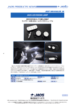
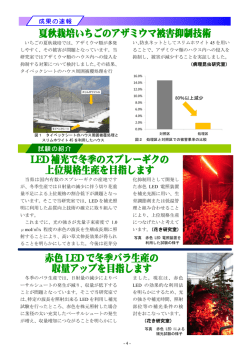
4. Chromaticity Diagram
0.9
0.37
520
0.36
0.8
510
0.7
0.35
550
M3
0.34
0.6
570
500
0.33
0.5
0.4
0.32
M0
0.3
610
700
0.2
0.0
0.1
0.2
0.30
0.29
470
450
0.0
M1
0.31
490
0.1
M2
y
y
590
0.3
0.4
x
0.5
0.6
0.7
0.8
0.28
0.31
0.32
0.33
0.34
0.35
0.36
x
※ Approved Rank
VF
CIE
Iv
A1, A2, A3, A4
M1, M2, M3
C1, C2, C3, C4
SAMSUNG LED
PAGE 4/18
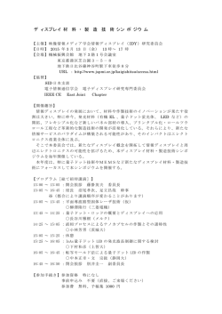
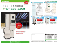
5. Typical Characteristics Graph
* These graphs show typical values.
( Ta : 25OC )
Forw ard Current vs.
Forw ard Voltage
Relative Luminous Intensity vs.
Forw ard Current
100
Forward Current
IF(mA)
Relative Luminous
Intensity (%)
1000
100
10
10
1
1
1
10
Forw ard Current(mA)
1.5
100
40
80%
Intensity (%
Forward Current (mA)
50
100%
30
20
60%
40%
10
20%
0
0%
20
40
60
80
Ambient Temp (deg)
100
50
80 90 80 70
70
60
60
40
30
20
10
0
100 80 60 40 20
120
400
500
600
700
800
Wav e L ength (nm)
Radiation Diagram
IF = 20 ㎃
Ta = R.T
4.0
Spectrum Distribution
Forward Current Derating Durve
0
2.0
2.5
3.0
3.5
Forw ard Voltage VF(V)
Y
X
50
40
30
20
0
10
0
20 40 60 80 100
Relative Luminous Intensity(%)
SAMSUNG LED
PAGE 5/18
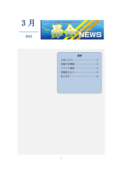
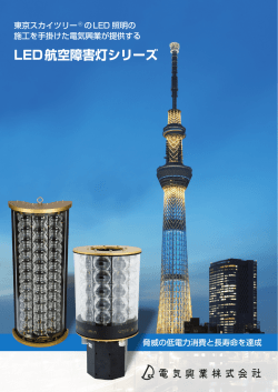
6. LED Package Outline Dimensions
unit:mm
Tolerance:±0.15
②
Cathode
1
2
①
# Do not place pressure on the encapsulating resin ("1")
The maximum compressing force is 15N on the polymer ("2")
Cathode
②
①
Anode
Land Layout
Circuit Diagram
④
⑤
②
③
①
⑥
NUMBER
ITEM
MATERIAL
①
FRAME
Copper Frame(Silver Plated)
②
LED CHIP
GaN/Al2O3
③
Zener Diode
Si
④
WIRE
Gold Wire
⑤
RESIN
Resin
⑥
PACKAGE
Heat-resistant Polymer
SAMSUNG LED
PAGE 6/18
7. Reliability Test Items and Conditions
1) Test Items
Preconditioning : JEDEC Level 2a
Test Item
Room Temp. Life Test
[AEC-Q101, JESD22-A108]
High Temp. Humidity Life Test
[AEC-Q101, JESD22-A101]
High Temp. Life Test
[AEC-Q101, JESD22-A108]
Low Temp. Life Test
[JESD22-A108]
High Temp. Storage
[AEC-Q101]
Low Temp. Storage
[AEC-Q101]
Thermal Shock
[MIL-STD-883]
Power Temp. Cycle
[AEC-Q101, JESD22-A105]
Temp. Humidity Cycle Test
Reflow Soldering
[JESD22-A113]
Test Conditions
Hours/Cycle
Sample
s
25℃±3℃, DC 30 ㎃
1000 hr
0/50
85℃±3℃, 85%±2%RH, DC 2 ㎃
1000 hr
0/50
85℃±3℃, DC 20 ㎃
1000 hr
0/50
110℃±3℃, DC 10 ㎃
1000 hr
0/50
-40℃±3℃, DC 30 ㎃
1000 hr
0/50
110℃±3℃
1000 hr
0/11
-40℃±3℃
1000 hr
0/11
1000 cycles
0/100
-40℃ DC 30 mA /110℃ DC 10 mA
[18 min, 18 min ] 온도 변경 42분 ,
on/off 5min
1000 hr
0/50
-10 ℃↔25 ℃,95 %RH ↔ 85 ℃,95
%RH[24 h/1 Cycle]
10 Cycle
0/50
3 times
0/50
5 times
0/5
3000G, 0.3ms, 각 6면(3축*2면)당 3회
3 times
0/11
20~80㎐(변위:0.06inch, Max 20G),
80~2㎑ (Max 20G), 최소주파수↔최대주파수
4min분 소요, X, Y, Z 축
4 times
0/11
-40℃ ~ 110℃ [15min, 15min]
Peak 260℃±5℃ for 10sec
ESD 2㎸
ESD(Human Body Model)
[EIAJ]
-R1:10 ㏁ , R2:1.5 ㏀ , C:100 ㎊
Mechanical Shock Test
[AEC-Q101]
Vibration Test
[IEC 1178-1.4.8.7, AEC-Q101]
SAMSUNG LED
PAGE 7/18
2) Criteria for Judging the Damage
Item
Symbol
Test Condition
Forward Voltage
VF
Luminous intensity
IV
Limit
Min
Max
IF = 20 ㎃
-
U.S.L.*1.2
IF = 20 ㎃
L.S.L.*0.5
-
* USL : Upper Standard Level
LSL : Lower Standard Level
8. Solder Conditions
1) Reflow Conditions ( Pb Free )
Reflow Frequency : 2 times max.
2) For Manual Soldering
Not more than 5 seconds @MAX300℃, under soldering iron.(one time only)
SAMSUNG LED
PAGE 8/18
9. Taping Dimension
①
②
Polarity
Start
End
More than 40 ㎜
Mounted with
More than (100~200)㎜
Leading part more than
Unloaded tape
Flash LED
Unloaded tape
(200~400)㎜
Tolerance
±0.2 , Unit:㎜
(1) Quantity : The quantity/reel to be 2000pcs.
(2) Cumulative Tolerance : Cumulative tolerance/10 pitches to be ±0.2 ㎜
(3) Adhesion Strength of Cover Tape : Adhesion strength to be 0.1-0.7N when the
cover tape is turned off from the carrier tape at 10℃ angle to be the carrier tape.
(4) Packaging : P/N, Manufacturing data code no. and quantity to be indicated on a
damp proof package.
SAMSUNG LED
PAGE 9/18
10. Label Structure
ⓐⓑⓒⓓⓔⓕ
A1M1C1
SPMWHT3212A3
A1M1C1
01
IIIIIIIIIIIIIIIIIIIIIIIIIIIIIIIIIIIIIIIIIIII
GLAR94001 / 1001 / 2,000pcs
Rank Code
IIIIIIIIIIIIIIIIIIIIIIIIIIIIIIIIIIIIIIIIIIII
N.B) Denoted rank is the only example.
Rank Code
ⓐⓑ
: Forward Voltage(VF) Rank (refer to page. 3)
ⓒⓓ
: Chromaticity Coordinate Rank
ⓔⓕ
(refer to page. 4)
: Luminous Intensity(IV) Rank (refer to page. 3)
11. Lot Number
The Lot number is composed of the following characters
A1M1C1
SPMWHT3212A3
A1M1C1
01
IIIIIIIIIIIIIIIIIIIIIIIIIIIIIIIIIIIIIIIIIIII
GLAR94001 / 1001 / 2,000pcs
IIIIIIIIIIIIIIIIIIIIIIIIIIIIIIIIIIIIIIIIIIII
●◎◇◆□■△△△ / I▲▲▲ / 2000PCS
● : Production Site (S:SEMCO, G:Gosin China)
◎ : L (LED)
◇ : Product State (A:Normality, B: Bulk, C:First Production, R:reproduction, S:Sample)
◆ : Year (Q:2006, R:2007, S:2008...)
□ : Month (1 ~ 9, A, B)
■ : Day (1 ~ 9, A, B ~ V)
△ : SEMCO. Product number (1 ~ 999)
▲ : Reel Number (1 ~ 999)
SAMSUNG LED
PAGE 10/18
12. Reel Packing Structure
Reel
LEVEL
2a
A1M1C1
SPMWHT3212A3
A1M1C1
01
IIIIIIIIIIIIIIIIIIIIIIIIIIIIIIIIIIIIIIIIIIII
GLAR94001 / 1001 / 2,000pcs
IIIIIIIIIIIIIIIIIIIIIIIIIIIIIIIIIIIIIIIIIIII
↓
Aluminum Vinyl Bag
A1M1C1
SPMWHT3212A3
A1M1C1
01
IIIIIIIIIIIIIIIIIIIIIIIIIIIIIIIIIIIIIIIIIIII
GLAR94001 / 1001 / 2,000pcs
IIIIIIIIIIIIIIIIIIIIIIIIIIIIIIIIIIIIIIIIIIII
↓
Material : Paper(SW3B(B))
TYPE
7inch
SIZE(mm)
ⓐ
ⓑ
ⓒ
245
220
182
① SIDE
A1M1C1
SPMWHT3212A3
A1M1C1
01
IIIIIIIIIIIIIIIIIIIIIIIIIIIIIIIIIIIIIIIIIIII
①
H
CHIP LED
GLAR94001 / 1001 / 2,000pcs
IIIIIIIIIIIIIIIIIIIIIIIIIIIIIIIIIIIIIIIIIIII
[Box Label]
SAMSUNG LED
W
L
PAGE 11/18
13. Aluminum Vinyl Bag
A1M1C1
SPMWHT3212A3
A1M1C1
01
IIIIIIIIIIIIIIIIIIIIIIIIIIIIIIIIIIIIIIIIIIII
GLAR94001 / 1001 / 2,000pcs
IIIIIIIIIIIIIIIIIIIIIIIIIIIIIIIIIIIIIIIIIIII
Silica gel
SAMSUNG LED
& Humidity Indicator Card in Aluminum Vinyl Bag
PAGE 12/18
14. Precaution for Use
1) For over-current-proof function, customers are recommended to apply resistors
to prevent sudden change of the current caused by slight shift of the voltage.
電圧の少しの変更により引き起こされる突然の電流変更を防ぐために過電流防止機能の
抵抗器を適用する ように勧めします。
2) This device should not be used in any type of fluid such as water, oil, organic
solvent, etc. When washing is required, IPA is recommended to use.
本製品は、水、油、有機的な溶剤などの任意のタイプの流体の中で使用しないで下さい。
洗浄が要求される場合、IPAを使用して下さい。
3) When the LEDs illuminate, operating current should be decided after considering the
ambient maximum temperature.
LED発光の時、動作電流はLED周囲の温度条件により使用電流を決めてください。
4) LEDs must be stored in a clean environment.
If the LEDs are to be stored for 3 months or more after being shipped from
SEMCO, they should be packed by a sealed container with nitrogen gas injected.
(Shelf life of sealed bags: 12 months, temp. 0~40℃, 20~70%RH)
本製品は清潔な大気を維持する環境で保存して下さい。
LEDが送られた後に3か月以上保存される場合、窒素雰囲気を備えた密封したコンテナー装置
に保管して下さい。(0~40℃以下、20~70%のRH以下とし12か月以内)
5) After storage bag is open, device subjected to soldering, solder reflow, or other
high temperature processes must be:
a. Mounted within 168 hours (7 days) at an assembly line with a condition of no
more than 30℃/60%RH,
b. Stored at <10% RH
開封後、Reflowハンダあるいは他の高温プロセスにさらされる場合は、
a. 工場条件30℃以下、60%RH以下の条件で168時間(7日)以内にマウントを完了して下
さい。
b. また10%のRHで保存して下さい。
6) Repack unused Products with anti-moisture packing, fold to close any opening
and then store in a dry place.
未使用のLEDが残った場合は、乾燥剤(シリカゲル)入り乾燥容器などで保管して下さい。
なお当社防湿袋に戻し、再封印することを推奨します。
SAMSUNG LED
PAGE 13/18
7) Devices require baking before mounting, if humidity card reading is >65%
at 23±5℃. 以下の場合、マウントする前にbakeすることをお勧めします。 23±5℃での湿度カードの表紙が65%以上の時
8) Devices must be baked for 24hours at 65±5℃, if baking is required.
Bakingが要求される場合、65±5℃で24時間Bakeすることをお勧めします。
9) The LEDs are sensitive to the static electricity and surge. It is recommended to
use a wrist band or anti-electrostatic glove when handling the LEDs.
If voltage exceeding the absolute maximum rating is applied to LEDs, it may cause
damage or even destruction to LED devices.
Damaged LEDs may show some unusual characteristics such as increase in leak
current, lowered turn-on voltage, or abnormal lighting of LEDs at low current.
本製品は静電気やサージ電圧に敏感で、素子の損傷や信頼性低下を起こすことがあります。
本LEDの取り扱いに際しては、手首バンドまたは静電気防止グローブ等の静電気対策を十分
行って下さい。
LEDに最大定格電圧値を超過される場合、LEDの損害を引き起こし、破壊する可能性があり
ます。
損傷したLEDには、漏洩電流が著しく大きくなり、順方向の立ち上がり電圧が低下したり
低電流で発光しなくなる等の異常が現れます。
SAMSUNG LED
PAGE 14/18
15. Hazard Substance Analysis
SAMSUNG LED
PAGE 15/18
SAMSUNG LED
PAGE 16/18
SAMSUNG LED
PAGE 17/18
Revision History
(Model:SPMWHT3212A3)
Date
Revision History
2010.01.05.
New Version
SAMSUNG LED
Writer
Drawn
Approved
W.H. Jung
Y.C. Kim
PAGE 18/18
© Copyright 2026 Paperzz