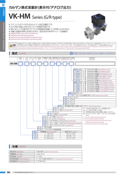
W
For Water
集合配管システム(カルマン渦式流量計)
TPS25/32-K Series
Piping System (Karman Vortex Flowmeter)
カルマン渦式流量計を搭載したトフパインシリーズです。
ヘッダ、バルブ、流量計をセットでご提供いたします。
豊富なバリエーションで、お客様の様々なニーズにお応えします。
設計工数、作業工数を削減いたします。
Tofpine Series with Vortex flow meter.
Header integrated with valve(s) and Vortex flow meter(s).
Unlimited variation to meet your needs.
Reduction in hours of design and work expected.
■
■
■
■
■
■
■
■
注意
Caution
計測精度を保つため、接続される配管及び継手は、流路径と同等または流路径以上の内径のものを使用、配管は、IN側に5D(口径の5倍)の直管部を設けて下さい。キャビテーションの発生を防止する
ため、流量計の下流側圧力は、次式より求めた圧力以上として下さい。 Pd=2.7△P+1.3Po Pd:下流側圧力〔kPa abs △P:圧力損失〔kPa〕 Po:液体の蒸気圧〔kPa abs〕
To ensure measurement accuracy, diameter of pipeline or coupling should be similar or larger than that of flow meter. For installation into inlet, use straight pipe with 5D. To prevent cavitation, following formula helps calculate outlet supply pressure of flow
meter. Pd=2.7△P+1.3Po Pd:Outlet pressure〔kPa abs △P:Pressure loss kPa〕Po:Steam pressure of Liquid〔kPa abs〕
型式
型式欄にご記入頂き、そのままFAXでもOK! お見積もり、ご注文承ります。
Type selection
本管 Main-Port
分岐 Sub-Port
本管規格
Main-Port std.
形状
Shape
TPS
記入例 e.g. :
-
本管 Main-Port
分岐 Sub-Port
バルブ 流れ方向
Valve
Shape
Identify model number(s) based on configurations from left.
接続口 取付姿勢 温度計測 オプション
最大流量 口径 継手形状 口径
Pipe size Temp. Measurement Option
Max. flow Connection size Fitting Options Connection size Inlet side
連数
# of port
-
K
各分岐が異なる場合、向かって左より記載。
-
B
-
-
-
-
-
特殊項目
For specif item
表示計 Flow indicator*5
予備ポート Spare port*6
TPS25-KG-S3-B20-03-A05B-D-TP-5RT
無記入 なし None
Blank
*1:ご使用条件により選定できる連数が限定されます。お問い合わせ願います。
オプション欄に表示計オプション記号を記入して下さい。
*2:EM40、EM45シリーズ搭載の場合、
オプション欄に変換器のオプション記号を記入して下さい。
*3:電圧出力の場合、
*4:各分岐の最大流量や口径が異なる場合は、向って左側より記載してください。
例)
「B5/10」
として位置は図面で示す。
オプション記号を記載願います。
*5:表示計・変換器のページを参照し、
形状「A」
・
・
・別置きの表示計を流量センサの数量分添付。
形状「G」or「R」
・
・
・表示計or変換器を搭載。対象:EM30、EM40、EM45、EX30シリーズ
*6:予備ポートの数量または位置を下記のように記載願います。
予備ポートを示す記号「P」
と数量を記載願います。
(予備ポートの位置は別途図面等で示します。)
例1)「-P2」
・
・
・系統数の内、2系統を予備ポートとする。
*1:Number of sub-port is limited depending on applications. Consult with us regarding this.
*2:For using EM40 or EM45 Series, specify an optional symbol in Option.
*3:For voltage output, specify the optional symbol of the Converter in Option.
*4:In case that there are some variations in flow ranges and connection sizes, specify them from the left channel when looking at this product.
e.g.) Specified as “B5/10” in model number(s) with details described in a drawing.
*5:Refer to Digital meter/Converter Page for optional symbol(s)
Shape “A”: The same quantity of remote display(s) are supplied as that of flow sensor(s)
Shape “G” or “R”: Display(s) or converter(s) is mounted. Mountable product Series is EM30, EM40, EM45 and EX30.
*6:Number of spare port(s) or position(s) should be specified as follows.
Specify “P”, which stands for Spare port, and the quantity of P. (Spare port position(s) are described in a drawing)
e.g. “-P2”:, 2 ports are regarded as Spare out of the available ports.
Pt1000温度計測付
Pt1000 Temperature sensor
installed.
底面取付 Installed on bottom side
背面取付 Installed on back side
TP
L
R
B
D
LR
A
L
V
LV
D
B
向って左側 Left side when looking at system
向って右側 Right side when looking at system
背面 Back side
底面 Bottom side
左右 Left and right
04 Rc3/4"
05 Rc1"
06 Rc1 1/4"
アダプタのみ Adapter only
エルボ Elbow
本管規格25Aのみ
バルブ Valve
対応可
エルボ+バルブ Elbow + valve Available for the TPS25 Series only.
01 Rc1/4"
04 Rc3/4"
02 Rc3/8"
R3 R1/2"
*4
03 Rc1/2"
R4 R3/4"
Max. 分岐の最大流量をご記入ください。Shows here max. flowrate. *4
(7連以上要相談)Shows here # of port (Consult with us for 7 ports or more)
連数 # of port 連数をご記入ください。
S
サプライ用 For supply
R
リターン用 For return
無記入 Blank バルブ無し With no needle valve
A
V
ボールバルブ Wih ball valve
B
アダプタ付ボールバルブ Ball valve with adapter
L
L型ニードルバルブ L type with a needle valve
N
ストレートニードルバルブ With straight needle valve
バルブは流量計のOUT側に付きます。
V、Lはリターン用で選択不可
Valve(s) is installed at the outlet side of flow meter(s)
V and L are not available for Return.
パルス出力 Pulse output
標準:EM30DT搭載 Std.:With Indicator EM30DT
G
表示計搭載 With Indicator*2
R
アナログ出力(変換器搭載)Analog output(Convertor-mounted models) *3
標準:EX30AR-I搭載(4-20mA出力)Std.:With analog converter EX30AR-I
分岐接続口径 Sub-Port std.
分岐流量 Sub-Port flow
サプライ用バルブ付 Valve for Supply
V、L
25
32
070
1∼10L/min
2∼20L/min*1
5∼50L/min*1
2016 Vol.1
Rc3/8"、1/2"
Rc1/2"、3/4"
リターン用バルブ付 Valve for Return
B、N
Rc1/4"∼1/2"、R1/2"
Rc3/8''∼1/2"、R1/2"
Rc1/2"∼3/4''、R1/2"
バルブ無し
With no valve
本管口径
Main-Port pipe size
Rc3/4"、Rc1"
Rc1"、Rc1 1/4"
W
液体用
仕様
Specifications
±5% of FS
使用最高圧力 Max. operating pressure
0.75MPa(G) at 50℃
使用流体温度 Operating fluid temperature
Max.90℃
(形状GorR:Max50℃)
使用環境温度 Ambient operating temperature
0∼50℃
(結露なきこと Non condensing)
標準電機仕様
A type
G type
Electrical specifications
パルス出力 Pulse output
プッシュプルトランジスタ出力 Max.33V Max.5mA Push-pull transistor output ... Max.33V, Max.5mA
電源 Power supply
DC5∼24V±10%
比較出力 Comparative output
NPNオープンコレクタ Max.DC35V 100mA Max. 2点 NPN Open collector Max.DC35V 100mA Max. 2 points
表示 Indication
LCD4桁、流量表示(瞬間値)Indication ofinstaneous
電源 Power supply
DC24V±10% 約90mA Max.
比較出力 Comparative output
リレー出力(C接点)Relay output (Contact C) Max.DC30V 100mA Max. 2点 Max. 2 points
アナログ出力 Analog output
DC4-20mA 負荷抵抗300Ω以下 Load resistance : Below 300Ω
電源 Power supply
DC24V±10% 約65mA Max.
TPS25/32-K
R type
集合配管システム
流量精度 Flow accuracy
※ G、
Rタイプのオプション仕様については、
各ページをご確認ください。Refer to Digital meter/Converter Page for G & R Type.
配線
Wiring diagram
A type
G type
AWG24(0.2mm2)
R type
AWG26(0.1mm2)
AWG28(0.08mm2)
線色 Cable colors
内容 Contents
線色 Cable colors
内容 Contents
線色 Cable colors
茶 Brown
+DC V
黄 Yellow
CP1
青 Blue
GND
(白 White)
(T1)
緑 Green
CP2
茶 Brown
アナログ出力 Analog output
青 Blue
パルス出力 Pulse output
白 White
COM
黄 Yellow
CP1(N.O.)
黒 Black
GND
黒 Black
GND
橙 Orange
CP1(N.C.)
(灰 Gray)
(T2)
赤 Red
+DC V
緑 Green
CP2(N.O.)
紫 Purple
CP2(N.C.)
※( )
は温度計測付のみあり。
※EM40、
EM45シリーズは、
各ページをご確認ください。
Items in parentheses are for temperature measurement.
Refer to Digital meter/Converter Page for detail of EM40 and EM45.
構造図
白 White
COM
黒 Black
DC 0V
赤 Red
DC +24V
Structural drawing
組み合わせ参考例
Example configurations
B
J
Φ
C
C
C
C
B
A
サプライ用
For supply
④
④
⑦
⑥
G1
R
G2
リターン用
For return
④
⑧
④
A
G3
④
④
④
④
⑦
⑦
⑧
⑧
G1
R
G2
G3
F
F
G
G
I
H
H
I
A
⑤
J
4-Φ
D
E
D
E
4-
内容 Contents
①
②
③
③
材質 Materials
No.
①
寸法表 A table of Dimensions
名称 Names of parts
材質 Mtl.
本管アダプタ Main-Port adapter
SCS13
2
マニホールド部 Part of the manifold
SCS13
3
本管プラグ Main-Port plug
SCS13
4
分岐アダプタ Sub-Port adapter
SCS13
5
L型ニードルバルブ L type with a needle valve
SCS13 他 etc.
6
ボールバルブ Ball valve
SCS13 他 etc.
7
ストレートニードルバルブ Straight needle valve SCS13 他 etc.
連結ボールバルブ A coupled ball valve
SCS13 他 etc.
名称 Names of parts
材質 Mtl.
流 パルス出力 Pulse output
SCS13 他 etc.
量
G1 計 EM30DT搭載 EM30DT mounted SCS13 他 etc.
EM40ET搭載 EM40ET mounted SCS13 他 etc.
G2
EM45RT搭載 EM45RT mounted SCS13 他 etc.
G3
No.
A
型式 Types A
B
C
D
E
F
G
H
I
J
TPS25 20 26.5 47 60 (70) 26.5 56 72 58 4.8
TPS32 24 36
66 76 (90) 34 66 82 59
6
Flowmeter
1
8
②
R
アナログ出力変換器:EX30AR-I
SCS13 他 etc.
Analog Converter : EX30AR-I
2016 Vol.1
071
© Copyright 2026 Paperzz