STAMPING
1
Increasing die life
and improving part quality
Factors that affect a stamping press’s productivity
By James Landowski
T
he ultimate goal of any stamping
operation is to provide the
highest-quality part with the highest
productivity and minimum possible
cost. The design and construction of
the bed, crown, and frame contribute to overall performance, but
other factors such as slide motion
and tooling impact also are
important when trying
to improve part
quality and
increase
die life.
THE FABRICATOR • FEBRUARY 2000
Basic Construction
Bed and frame rigidity and proper
press foundation isolation play a part
in dispersing the forces encountered
in stamping operations. Using highdampening-level press-mounting isolators also enhances the tool life compared to bolting the press directly to
the floor. Using press mounts helps
to keep the press properly leveled,
which affects press and die life.
The overall press construction
should use full-length tie-rods to
“join” the key press member of the
crown, uprights, and bed. Newer press
designs offer taller, thicker beds and
uprights, as these members deflect
much less than older designs with
low-profile beds and shallower frames.
(For example, 2 by 4 rafters in a house
are placed with the taller 4-inch- high
side bearing the weight of the roof
because the 4-inch height is stronger
than the 2-inch thickness.)
Slide Motion
Another key to longer die life and
better part quality is minimizing the
lateral movement of the moving
part of the tooling (punch) in
relation to the fixed part of the
mating tooling (die). Fundamentally, a press should be
designed to manage or control the
punch’s movement by controlling
the slide’s movement.
Most press designs dedicate
the job of guiding or controlling the slide vertical
motion to the slide
gibs only. These gibs
must control not
only the normal
eccentric movement
of the drive but also
load forces generat-
2
STAMPING
Eccentric Circle
Side Thrust to
Plunger Guide
Plunger Guide
Gib
Gib
Figure 1
When a plunger is combined with gibbing, more slide-guiding area is provided.
120 SPM
4.9" Stroke
Motion Diagram
160
14.00
0.70
150
12.00
0.60
140
10.00
0.50
130
8.00
0.40
120
6.00
0.30
110
4.00
2.00
0.00
0.20
0.10
0.00
Stroke (mm)
0.80
Velocity (m/s)
16.00
100
90
80
-0.10
70
-4.00
-0.20
60
-6.00
-0.30
50
-8.00
-0.40
40
-10.00
-0.50
30
-12.00
-0.60
20
-14.00
-0.70
10
-16.00
-0.80
0
-2.00
Stroke
Velocity
Acceleration
0
30
60
90
120 150 180 210 240 270 300 330 360
Crank Angle (deg)
Motion Diagram
1.40
1.20
140
130
25.00
20.00
15.00
1.00
0.80
0.60
120
110
100
90
80
10.00
5.00
0.00
-5.00
-10.00
-15.00
-20.00
-25.00
-30.00
-35.00
0.40
0.20
0.00
-0.20
-0.40
Stroke (mm)
35.00
30.00
Velocity (m/s)
Acceleration (m/s2)
Link Motion
Another factor that affects die life is
the effect of reverse loads, or
snapthrough, during blanking or severe
punching operations. The energy released after the breakthrough in the
material, which occurs after the punch
has penetrated 20 to 30 percent of the
material thickness, propels the slide
downward at a high velocity.
This sudden increase in velocity
near the bottom of the stroke causes
severe shock to both the press and the
Side Thrust to
Gib and Slide
Length of
Slide Guide
L1 > L2
Acceleration (m/s2)
ed by the tooling. Gibs usually must
be replaced regularly. However, by
using an additional component
called a plunger guide in this guide
train, both tool and gib life can be
increased.
A plunger-guided slide design
absorbs the normal side thrust of the
eccentric drive and directs these
forces away from the slide. With the
thrust redirected, the gibs’ job then is
to guide the slide against the forces
generated by the tooling. Full-length
gibs must be used so that the slide
remains completely guided throughout the entire stroke. This combination of plunger guide and full-length
gibs provides more than twice the
slide-guiding area compared to designs with only gibbing for slide guidance (see Figure 1).
With this design and by using oil
lubricants rather than grease, gib clearances can be set closer (0.0015 inch
nominally) than nonplunger-guided
designs (typically, 0.008 to 0.015 inch).
Using a close-tolerance, precision
system to guide the slide controls the
punch’s movement. While this system costs more initially than nonplunger-guided systems, it can increase die life by 30 percent.
-0.60
-0.80
70
60
50
40
30
-1.00
-1.20
-1.40
20
10
0
120 SPM
4.9" Stroke
Stroke
Velocity
Acceleration
0
0
30
60
90 120 150 180 210 240 270 300 330 360
Main Gear Angle (deg)
30
60
90 120 150 180 210 240 270 300 330 360
Crank Angle (deg)
Figure 2
These charts show the difference in slide motion between an eccentric drive
press (Figure 2a) and a link motion press (Figure 2b).
FEBRUARY 2000 • THE FABRICATOR
STAMPING
tooling. The slide’s velocity at the
point of this breakthrough is linked
directly to the amount of reverse
load generated.
To combat this effect, a link motion drive can be used to reduce the
slide velocity (touch speed) near the
bottom of the stroke to about 40 percent that of a crank motion press at
the same stroke-per-minute (SPM)
rate. The touch speed of the slide to
the dies and the impact force on the
dies are about 60 percent that of a
crank motion press. This reduced velocity means reduced impact between
the upper and lower dies, which can
increase die life.
Because the slide velocity remains
reduced until after the bottom of the
stroke, parts remain in the working
cycle of the stroke longer. A longer
pressing time can be beneficial, especially in coining and forming appli-
THE FABRICATOR • FEBRUARY 2000
cations in which slower speeds are
preferable to provide higher accuracy
and associated part quality.
The charts in Figure 2 show the
difference in slide motion between
an eccentric drive press and a link
motion press. The chart of the link
motion press shows both a reduction
of the slide velocity near the bottom
and the reversal of link motion beyond 180 degrees.
While link motion drive reduces
snapthrough, it offers a smaller feed
angle, or window, for feeding material in a continuous mode of operation
than an eccentric drive has. The
higher acceleration of the slide after
bottom position limits the feed length
or pitch that can be achieved during
the feed cycle. The initial cost of the
drive also is higher than that of an
eccentric drive.
3
Conclusion
To stay competitive in a demanding global market, higher output and
quality are essential. Don’t rely only
on your tooling to make a good part.
Instead, consider the press as an integral part of the overall production
system. ■
James Landowski is Manager of Sales Administration, Komatsu America Industries
LLC, 199 Thorndale Avenue, Wood Dale,
Illinois 60191, phone 630-860-3000, fax
630-860-5680. Komatsu is the international press builder of OBS single-point and
OBW two-point gap presses; E2G generalpurpose straight-side presses; E2M higherspeed progressive-die straight-side presses;
and specific-application presses for cold/
warm and hot forging, transfer presses, and
hydraulic presses.
Reprinted with permission from the February
2000 issue of The FABRICATOR®, copyright
2000 by The Croydon Group, Ltd., Rockford,
Illinois, www.thefabricator.com
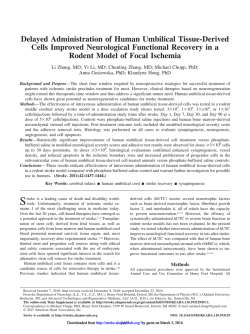
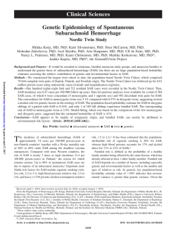
© Copyright 2026 Paperzz