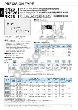
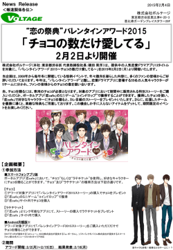
PRECISION TYPE
RN26
RNF26
RK26
リードフレームラジアル形金属皮膜固定抵抗器
Lead Frame Radial Type Metal film Fixed Resistors
リードフレームラジアル形難燃性塗装金属皮膜固定抵抗器
Lead Frame Radial Type Flame Retarant Coat Insulated Metal Film Fixed Resistors
リードフレームラジアル形メタルグレーズ皮膜固定抵抗器
Lead Frame Radial Type Glazed Metal Film Fixed Resistors
■構造図 Construction
③
②
①
④
⑦
⑤
⑥
外装色:ブルー Coating color:Blue
表示:カラードット Marking:Color dot
Insulation coating
① 絶縁塗装
② 表示
Marking
③ トリミングライン Trimming line
Ceramic core
④ セラミック
End cap
⑤ 電極キャップ
⑥ 端子
Lead frame
⑦ 抵抗皮膜 Resistive film
■特長 Features
L形
(端子間隔2.54mm
(2C)
、5.08mm
(2E)
及び7.5mm
(2H)
)フレームを採用しており、高密度実装が可能で自立強度も優れています。
RK26は100kΩから33MΩまで対応できます。
● Suitable for high density mounting and excellent in self-standing strength with L-shape leads frame
(lead pitch 2.54mm
(2C)
, 5.08mm
(2E)
and 7.5mm
(2H)
)
.
● RK26 is available from 100kΩ to 33MΩ.
●
●
■品名構成 Type Designation
例 Example
RN26
C
2E
T
A
10kΩ
J
品種
Product Code
抵抗温度係数
T.C.R.
(ppm/℃)
C:±150
K:±100
B:±350
定格電力
Power
Rating
2C:0.125W
2E:0.25W
2H:0.5W
二次加工
Taping
包装
Packaging
公称抵抗値
Nominal
Resistance
抵抗値許容差
Resistance
Tolerance
D:±0.5%
F :±1%
G:±2%
J :±5%
RN26 :金属皮膜
RN26 :Metal film
RNF26:難燃性塗装
RNF26:Flame retardant coating
RK26 :メタルグレーズ皮膜
RK26 :Glazed metal film
空欄:バルク
Nil:Bulk
T:テーピング(2C,2E)
T:Taping(2C,2E)
空欄:バルク
Nil:Bulk
A:アモパック(2C,2E)
A:AMMO
(2C,2E)
テーピングの詳細については巻末のAPPENDIX Cを参照して下さい。
For further informations of taping, please refer to APPENDIX C on the back pages.
■参考規格 Reference Standard
IEC 60115-2
JIS C 5201-1
■定格 Ratings
形 名
Type
RN26C2C
RN26K2C
RNF26C2C
RNF26K2C
RN26C2E
RN26K2E
RNF26C2E
RNF26K2E
RN26C2H
RN26K2H
RK26B2E
定格電力
Power
Rating
0.125W
0.125W
0.25W
0.25W
0.5W
0.25W
最高使用電圧
抵 抗 値 範 囲
抵抗温度係数
Resistance Range(Ω)
Max.
T.C.R.
D:±0.5% F:±1%
G:±2%
J:±5%
Working
(ppm/℃)
E96
E96
E24
E24
Voltage
C:±50
44.9∼562k
10∼1M
1∼1M
1∼1M
200V
K:±100
C:±50
―
10∼100k
1∼100k
1∼100k
200V
K:±100
C:±50
10∼1M
10∼1M
1∼1M
1∼1M
250V
K:±100
C:±50
―
10∼100k
1∼100k
1∼100k
250V
K:±100
C:±50
10∼1M
10∼1M
1∼1M
1∼1M
350V
K:±100
B:±350
―
100k∼22M 100k∼33M 100k∼33M
500V
最高過負荷電圧
耐 電 圧 テーピングと包装数
Max.
Dielectric Taping&Q’ty/AMMO
Overload Withstanding (pcs)
Voltage
Voltage
定格周囲温度 Rated Ambient Temperature :+70℃
使用温度範囲 Operating Temperature Range :−55℃∼+155℃
定格電圧は √
定格電力×公称抵抗値による算出値、又は表中の最高使用電圧のいずれか小さい値が定格電圧となります。
 ̄ ̄ ̄ ̄ ̄ ̄ ̄ ̄ ̄
Rated voltage=√ ̄ ̄ ̄ ̄ ̄ ̄ ̄ ̄ ̄ ̄ ̄ ̄
Power Rating×Resistance value or Max. working voltage, whichever is lower.
本カタログに掲載の仕様は予告なく変更する場合があります。御注文及び御使用前に、納入仕様書などで内容を御確認下さい。
Specifications given herein may be changed at any time without prior notice. Please confirm technical specifications before you order and/or use.
400V
500V
400V
250V
500V
500V
500V
250V
700V
500V
―
700V
500V
2,000
2,000
■外形寸法 Dimensions
■負荷軽減曲線 Derating Curve
定 挌 電 力 比(%)
D
h
L
H
0.3±0.05
Percent rated load
100
0.5±0.1
80
60
40
20
0
-60
-55
-40
RN26 2H
L Max.
5.0
7.25
10.5
0
20
40
60
80
70
100 120 140
160
155
周囲温度 Ambient temperature(℃)
P
形 名
Type
RN26 2C
RNF26 2C
RN26 2E
RNF26 2E
RK26 2E
-20
寸 法 Dimensions
(mm)
Weight
(g)
D Max. P±0.3
H±1
h Max. (1000pcs)
260
2.54
2.54
3.0
Taping
5.5
370
2.54
5.08
Taping
5.0
172
3.50
7.50
6.0
Bulk
周囲温度70℃以上で使用される場合は、上図負荷軽減曲線に従って、定格
電力を軽減して御使用下さい。
For resistors operated at an ambient temperature over 70℃, power rating
shall be derated in accordance with the above figure.
■性能 Performance
試験項目
Test Characteristics
抵抗値
Resistance
抵抗温度係数
T.C.R.
短時間過負荷
Short time overload
断続過負荷
Intermittent overload
はんだ耐熱性
Resistance to soldering heat
はんだ付け性
Solderability
試験方法 JIS C5201-1 準拠
Test Methods JIS C5201-1
室温/100℃ up
Room temperature/100℃ up
定格電圧×2.5倍又は最高過負荷電圧の低い方を5秒印加
Rated voltage × 2.5 or MAX. overload vol. for 5s, whichever less
定格電圧×4倍又は最高過負荷電圧の低い方を10,000回印加
Rated voltage × 4 or MAX. overload voltage.
for 10,000 cycles, whichever less
最高過負荷電圧
Max. overload voltage
2C
400V
2E
500V
2H(RK26 2E)
700V
規格値
Performance Requirments
規定の許容差内
Within regulalted tolerance
規定値内
Within specified T.C.R.
±
(0.5% + 0.05Ω)
±
(1.0% + 0.05Ω)
耐電圧
Dielectoric withstnding voltage
500V, 1分間, V-ブロック
500V, 1min, V-block
絶縁抵抗
Insulation resistance
温度サイクル
Temperature cycling
100V, 1分間
100V, 1min.
−55℃(30min.)
/+155℃(30min.)5サイクル
−55℃(30min.)
/+155℃(30min.)5cycles
±
(0.5% + 0.05Ω)
:RN26, RNF26
±
(1.0% + 0.05Ω)
:RK26
95% 以上が新しいはんだで覆われていること。
95% Coverage min,
±
(0.5% + 0.05Ω)
:RN26, RNF26
絶縁破壊しないこと。
No evidence of mecanical damage.:RK26
1,000MΩ以上
Not less than 1,000MΩ
±
(0.5% + 0.05Ω)
:RN26, RNF26
±
(1.0%)
:RK26
耐久性
(耐湿負荷)
Moisture resistance
40℃±2℃, 90%∼95%RH, 1.5時間 ON/0.5時間 OFFを1,000h,
1.5h ON/0.5h OFF cycle
±
(2% + 0.05Ω)
:RN26, RNF26
±
(5%)
:RK26
耐久性
(定格負荷)
Load life
70℃±2℃, 1.5時間 ON/0.5時間 OFFを1,000h
1.5h ON/0.5h OFF cycle
耐溶剤性
Resistance to solvent
イソプロピルアルコールに5分間浸せきする
The resistor shall be completely immersed for 5min in IPA
±
(2% + 0.05Ω)
:RN26, RNF26
±
(5%)
:RK26
外観に異常がなく、表示は容易に判読できること。
No evidence of mechanical damage.
The marking shall remain legible.
350℃±5℃, 3.5s±0.5s
235℃±5℃, 5s±0.5s
本カタログに掲載の仕様は予告なく変更する場合があります。御注文及び御使用前に、納入仕様書などで内容を御確認下さい。
Specifications given herein may be changed at any time without prior notice. Please confirm technical specifications before you order and/or use.
© Copyright 2026 Paperzz
![水力発電所 簡易型IP-TCの開発[PDF:733KB]](http://s3.paperzz.com/store/data/005403186_1-0b4731aff206e5b567d5838f2796c4e4-250x500.png)