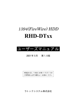
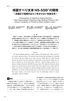
※組立てる前にこの説明書を良くお読みになり充分に理解してください。
Before commencing assembly, please read these instructions thoroughly.
INSTRUCTION MANUAL
R
THE FINEST RADIO CONTROL MODELS
上級者向
For Advanced
flyers.
組立/取扱説明書
RADIO CONTROLLED ENGINE POWERED HELICOPTER
キャリバー 60
SAFETY PRECAUTIONS
この無線操縦模型は玩具ではありません!
●高速で回転するローターが付いた危険性のある機械
です。組立て、飛行(場所、電波)、点検、整備はご自身が
責任をもって行ってください。これはあなたの責任です。
●小さい部品が多いので、組立て作業は、必ず幼児の
手がとどかない所で行ってください。
●フライト前、フライト後は必ず、ビスの緩み、各部
品の劣化などを点検し、異常があれば交換・修理・
調整を行い、安全を確認してからご使用ください。
●純正部品以外のパーツを使用しないでください、事
故や不調の原因になるおそれがあります。また、
社外品を使用しての事故、破損等については、一切
責任を負いません、ご了承ください。
●組立て後に、もう一度説明書を見直して下さい。
説明書は、いつでも見られるように大切に保管して
ください。
This radio control model is not a toy.
●This is a kind of machine including a rotor which rotates with
high speed and has a possibility to be dangerous. You are
responsible for this model's assembly, safe operation (place
to fly, frequency) check and adjustment of the model.
●Assemble this kit only in places out of children's reach!
●Take enough safety precaution before and after operation.
After every flight, inspect screws and nuts for looseness, and
parts for wear. Any damaged parts should be immediately
replaced, repaired or adjusted for safe operation.
●Use only Kyosho genuine parts for replacement.
Failing to do so will result in accidents or malfunction of the
model. Kyosho do not take responsibilities for the accidents
and crashes if using the parts which are not Kyosho genuine
ones.
●Always keep this instruction manual ready at hand for quick
reference, even after completing the assembly.
※製品改良のため、予告なく仕様を変更する場合があります。 SPECIFICATIONS ARE SUBJECT TO CHANGE WITHOUT NOTICE.
© 1999 KYOSHO/禁無断転載複製
No. 21865
キットの他にそろえる物(1)REQUIRED FOR OPERATION (1)
エンジンヘリ用無線操縦機(プロポ) ■エンジンヘリ用プロポ
Radio for engine-powered
と電池
R/C helicopters
1
Radio for engine-powered R/C helicopters,
and dry batteries
使用できるサーボサイズ
●This kit requires an EMS system radio for
engine-powered R/C helicopters with 5
servos and 1 gyro.
●For more information the radio, refer to the
instruction manual supplied with the set.
2
Engine and Muffler
1
2
UAL
CDONVERSION
3
4
9 CHANNEL
RECEIVER
6
CONNECT
7
8
9/B
DSC
33~36mm
39~41mm
19~20mm
注意
空用(ヘリ用)のプロポセットを必ず
使用してください。(空用以外使用禁止)
CAUTION: Only use a radio for R/C helicopters! (Any other radio is prohibited!)
本説明書のプロポイラストは、Futaba取扱説明書より転載しました。
The illustration of the radio shown here is taken from Futaba instructions.
■ヘリ用60クラスエンジン
.60 size engine for helicopters
グロー燃料、燃料ポンプ
Glow Fuel and Fuel Pump
●模型用エンジンは専用のグロー燃料が必要です。ガソリンや灯油は使用できませんので注意して
ください。また、グロー燃料は揮発性が高く引火しやすいので取扱いには充分注意してください。
● 燃料は、ニトロ分 15 % 以上が適しています。
■マフラー
Muffler
●Engines for R/C models require glow fuel. Never use gasoline (petrol) or kerosene; both cannot
be used! Also, be very careful when handling glow fuel, as it is highly flammable and explosive!
●Fuel should contain at least 15% of nitro metane.
ガソリンや灯油は
使用禁止
■グロー燃料
Glow Fuel
■ラダーサーボ用延長
コード(300mm)…1本
Extension Cord for
Rudder Servo (300mm)
■メインローター
Main Rotor Blades
長さ: Length
/ 660 mm
取付穴: Hole size / 5 mm
厚さ: Thickness / 12 mm
4
RATE GYRO
5
PULSE CODE MODULATION
3
エンジン/マフラー
ジャイロ
SUITABLE SERVOS
●このキットにはエンジンヘリ用
EMSシステム対応(5サーボ+ジャイロ)の
プロポが必要です。
●プロポの取扱いは、プロポに付属の説明書
を参考にしてください。
警告
Glow Fuel
model en
■スターター
Starter
始動用具
Required for engine starting:
■燃料ポンプ
Fuel Pump
● No. 80701 燃料ポンプ(電動12V)
Fuel Pump (Electric 12V)
e fuel
gin
5
● No. 80702 燃料ポンプ(手動)
Fuel Pump (Manual)
■グリス
Grease
接着剤等
Glues & Lubricants
●No. 1791 ブリッツスターター
Blitz Starter
●ロックタイト Loctite
No. 94402 中強度
Medium Strength
■スターター用12Vバッテリー
12V Battery
No. 94403 高強度
Hard Strength
●No. 96815 ワンタッチプラグヒーター
One-touch Plug Heater
●No. 71481 シールドバッテリー
Sealed Battery
(12V-6.5A)
■スターター シャフト
Starter Shaft
Grease
■ネジロック剤
Screw Locking Compound /
Screw Cement / Threadlocker
■プラグヒーター
Plug Heater
WARNING: Gasoline
or kerosene cannot
be used!
6
● No. 96506 ボールデフグリス
Ball Diff Grease
■瞬間接着剤
Instant Glue (Super Glue)
● No.96627
クイックタイトジェルボーイ
Gel Boy
さらに用意すると良いもの
Useful Additional Equipment
■燃料フィルター
Fuel Filter
●No. Z8020 HP 6mm/六角ツーウエイスターターシャフト
HP 6mm Hexagon Reversible Starter Shaft
●No. 39508 燃料フィルター
Fuel Filter
キットの他にそろえる物(2) REQUIRED FOR OPERATION (2)
7
組立てに必要な工具
※使用する工具の取扱いには、充分注意してください。
Tools required
■六角レンチ(1.5mm, 2mm, 2.5mm, 3mm)
Hex Wrench (1.5mm, 2mm, 2.5mm, and 3mm)
Handle the tools carefully!
■ラジオペンチ
Needle Nose Pliers
2
Sharp Hobby Knife
■+ドライバー(小)
Phillips Screw Driver (S)
■キリ
Awl
■ニッパー
■プラグレンチ
Glow Plug Wrench
■カッターナイフ
Wire Cutters
スペシャルテーパーリーマー
SPECIAL TAPER REAMER No.80311
下穴加工が不要で、直接1mm∼15mm
の穴あけができる工具です。
No need to pre-drill!
Drills neat 1 ~ 15mm holes directly!
プロポの準備 RADIO PREPARATION
●プロポを下の順番にしたがってセットします。
CH1
エルロンサーボ
Aileron Servo
CH2
エレベーターサーボ
Elevator Servo
CH3
スロットルサーボ
Throttle Servo
Set up the radio as explained below.
3
ジャイロ(GY501の場合) Gyro(In GY501 case)
1
2
3
UAL
CDONVERSION
4
5
PULSE CODE MODULATION
6
RATE GYRO
7
9 CHANNEL
RECEIVER
8
CONNECT
9/B
DSC
R149DP受信機 R149DP Receiver
CH4 ラダーサーボ
Rudder Servo
ニッカド電池
Nicd Battery
2
受信機スイッチ
Receiver Switch
充電口
Terminal to charge
送信機
Transmitter
4
●リバーススイッチ Reverse Switch
エルロン Aileron
リバース Reverse
スロットル Throttle
ラダー Rudder
エレベーター Elevator
ノーマル Normal
ピッチ Pitch
CH6
ピッチサーボ
Pitch Servo
フタバ 1024 ZH の場合
In Futaba 1024ZH case.
EMS の設定 EMS setting
MDL を選択 (モデルメニューが開く)
Select MDL to open model menu.
1
5 -2 タイプの設定で
Select
SR3
を選択する。
SR3 in Swash Type Menu.
選択
Select
2
選択
Select
5 -1 AIL , ELE , PIT の作動量、作動方向を設定する。
Select the way and volume of AIL, ELE, PIT movement.
3
選択
Select
JR プロポの場合
In case of JR radio
65 SWASH MIX
3 SERVOS (120¡)
AILE
- 65
エルロン
- 65
エレベーター ELEV
PITCH + 65
ピッチ
●始める時
4
数値はスワッシュプレートの作動量
Figure indicates the volume of Swashplate movement.
+、ーはスワッシュプレートの作動方向
+, ー indicate a direction of swashplate movement.
●START
1 上図に従い、各サーボ等を受信機に接続する。
2 トリムを中央にセットする。(送信機)
1 Connect servos to the receiver using the illustration above.
2 Set trims to center. (Transmitter)
3 スイッチを入れる。(送信機)
4 各設定画面を開く。(送信機)
3 Switch on the transmitter. (Transmitter)
5 図を参考に各設定を行う。(送信機)
5 Set up the data following the illustration. (Transmitter)
6 スイッチを入れる。(受信機)
6 Switch on the receiver. (Receiver)
7 スティックを動かしてサーボが動いているか確認。
7 Make sure the servos move according to
4 Open the setting menu. (Transmitter)
your transmitter inputs.
●終わる時
8 送信機のスティックを中立にする。(送信機)
9 スイッチを切る。(受信機)
10 スイッチを切る。(送信機)
11 アンテナを縮める。(送信機)
●FINISH
8 Set transmitter sticks to neutral. (Transmitter)
9 Switch off the receiver. (Receiver)
10 Switch off the transmitter. (Transmitter)
11 Retract the antenna. (Transmitter)
3
組立て前の注意(1) BEFORE YOU BEGIN (1)
1
組立てる前に説明書を良く読んで、おおよその構造を理解してから組立てに入ってください。
2
キットの内容をお確かめください。万一不良、不足がありましたら、お買い求めの販売店にご相談いただくか、
当社「ユーザー相談室」までご連絡ください。
Read through the manual before you begin, so you will have an overall idea of what to do.
Check all parts. If you find any defective or missing parts, contact your local dealer or our Kyosho Distributor.
3
説明書の見かた
〔説明例 Example〕
How to read the instruction manual:
9
テール
Tail
HH-2
2.6 x 10mm キャップビス
Cap Screw
2
3 x 3mm セットビス
Set Screw
1
2.6mm ナイロンナット
Nylon Nut
説明書内では多くのマークが使用
されています。マークに注意して
組立てを進めてください。
This instruction manual uses several symbols. Please note them
during the entire assembly.
2.6mm
2
3 x 3mm
小物部品の名前、原寸図、使用数。
Key Number, Part Name, True-to-scale
Diagram, Quantity Used
4
2.6 x 10mm
テールローターアッセンブリー
Tail Rotor Assembly
キット内の部品は、ビス類を除いてキー
No.が付けられています。スペアパーツを
購入する時はキーNo.を参照して下さい。
All parts except screws are identified by
key numbers. For purchasing spare parts,
find the key no. of the part needed in the
spare part list and refer to the left column
to look up the corresponding order no.
説明書に使われているマーク
Symbols used throughout the instruction manual, comprise:
使用する袋詰。
Part bags used.
エポキシ接着剤で接着する。
Apply epoxy glue.
4
92
x2
番号の順に組立てる。
Assemble in the specified
order.
注意して組立てる所。
Pay close attention here!
2セット組立てる(例)。
Assemble as many times as
specified (here: twice).
別購入品
Must be purchased separately!
ネジロック剤を塗る。
Apply threadlock (screw cement).
原寸図
True-to-scale diagram.
グリスを塗る。
Apply grease.
2mmの穴をあける(例)。
Drill holes with the specified
diameter (here: 2mm).
2mm
瞬間接着剤で接着する。
Apply instant glue (CA glue, super glue).
をカットする。
Cut off shaded portion.
左右同じように組立てる。
Assemble left and right sides
the same way.
仮止め。
Tempororarily tighten.
BEFORE YOU BEGIN (2)
5
キット内の部品の中には、組立済みの部品があります。
念のためビス等のゆるみが無いか確認してから、組立て
てください。
Inside the kit, you will find assemblies, i.e. sections that are pre-assembled
and hence consist of more than one part. To make sure these assemblies
are safely assembled, check among others their screws for looseness. Only
then, build in the assemblies.
6
キットには、形や長さが違うビスや小物部品が多く入っています。説明書には原寸図がありますので確認してから組立て
てください。また、ビス類は多めに入っているものもありますので、予備としてお使いください。
This kit contains screws and hardware in different metric sizes and shapes. Before using them, check the screws on the true-to-scale diagrams on the
left side in each assembly step. Some screws are extras.
●ビスの種類 SCREWS
ビス Screw
●小物部品のサイズ例 OTHER HARDWARE
TPビス
Self-tapping (TP) Screw
3x12mm ビス
Screw
3mm ワッシャー・ナット
Washer・Nut
3mm
サラビス
Flat Head (F/H) Screw
E4 Eリング
E-ring
キャップビス
Cap Screw
3mm
12mm
TPサラビス
TP F/H Screw
セットビス
Set Screw
5x10mm メタル・ベアリング
Metal Bushing・Bearing
5mm
4mm
10mm
7
TPビスは、部品にネジを切りながらしめつけるビスです。しめこみが固い場合が
ありますが、部品が確実に固定されるまでしめこんでください。 ただし、しめす
ぎるとネジがきかなくなりますので、部品が変形するまでしめないでください。
Self-tapping (TP) screws cut threads into the parts when being tightened. Excessive force may
Correct
Wrong
permanently damage parts when tightening TP screws. It is recommended to stop tightening when
the part is attached or when some resistance is felt after the threaded portion enters the plastic.
パーソナルバンドモニターについて
しめすぎ
Overtightened.
ビスがきかない
The threads are stripped.
ABOUT THE "PERSONAL FREQUENCY MONITOR"
愛機の飛行前に、使うバンドのクリスタルをセット
してスイッチオン! 同一バンドの電波をキャッチ
するとブザー音とLEDの光で警告。
Before operating your helicopter, plug the crystal of your
frequency into the Personal Fre-quency Monitor. As soon
as you switch it on, you'll know for sure through an interfe-rence signal and LED lamps whether somebody else is
on your fre-quency or not!
No.80591 (40MHz)
No.80592 (72MHz)
PERSONAL
BAND MONITOR
40MHZ
KYOSHO
CORPORATION
ON
OFF
No.80591
●6,000
専用クリスタル別売
Special crystals are
available at Kyosho!
JRMSA
KYOSHO CORPRATION
77
5
この説明書は本品の構造をご理解いただくために、組立済のアッセンブリ−部分やベアリング等の接着済
部分も組立ていただくように説明しています。オーバーホール、部品交換等のときに参考にしてください。
In Order to understand full assembly sequence, this instruction manual shows the complete assembly of this model,
even though some elements are supplied pre-built. please refer to it when carrying out maintenance or replacing parts.
1
ラダ−フレーム
Ladder Frame
CA-1.CA-2
610
ベアリング組立済
Ball Bearing pre-installed
707 12x24x6mm ベアリング
Ball Bearing
602
2
707
708
708
707
708 7x17x5mm ベアリング
Ball Bearing
2
2
ラダ−フレーム
Ladder Frame
603
3x10mm
CA-1,CA-2
3x10mm キャップビス
Cap Screw
3x8mm
8
3x8mm キャップビス
Cap Screw
610
5
604
647
602
647 3x4x4.5mm カラー
Collar
647
8
603
向きに注意。
Note the direction!
708
3x10mm
601
6
使用する袋詰。
ネジロック剤を塗る。
Part bags used.
Apply threadlock
(screw cement).
602
3
CA-B,CA-1,CA-2
ラダ−フレーム
Ladder Frame
4x10mm キャップビス
Cap Screw
2
3x10mm キャップビス
Cap Screw
605
4
3x10mm
606
4x10mm
4
サーボプレート
Servo Plate
CA-C,CA-1,CA-2
709
3x10mm キャップビス
Cap Screw
6
3x6mm キャップビス
Cap Screw
10
709 5x11x5mm Fベアリング
Flanged Ball Bearing
外側
Outside
709
内側
Inside
611
3x10mm
接着済
glued
3x6mm
3x14mm
611
608
2
727
608
3x14mm セットビス
Set Screw
699
4
611
609
3x6mm
607
3x10mm
3x10mm
698 短い方
Short Body Mount
3x14mm
使用する袋詰。
Part bags used.
ネジロック剤を塗る。
左右同じように組立てる。
仮止め。
Apply threadlock
(screw cement).
Assemble left and right sides the same way.
Temporarily tighten.
7
5
プーリー
Pulley
CA-B
710 10x19x5mm ベアリング
Ball Bearing
組立済
pre-assembled
710
刻印があるほうが下
Mark should be this way down
塗布済 補充はNo96506ボールデフグリス
を必ず使用する。
Be certain to apply 96506 ball diff.grease
711
2
上
Top
612
711 10x16x12mm ワンウェイベアリング
One Way Bearing
下
Bottom
710
1
6
CA-B
CA-3
プーリー
Pulley
615
3x5mm
616 7x13x1.5mmカウンターギヤ カラー
Counter Gear Collar
1
ベルトを折らないように注意。
Be careful not for being bent.
614
3x5mm セットビス
Set Screw
A
2
616
617
613
Aへ
3x5mm
8
使用する袋詰。
ネジロック剤を塗る。
グリスを塗る。
Part bags used.
Apply threadlock
(screw cement).
Apply grease.
注意して組立てる所。
Pay close attention here!
7
メインマスト
Main Mast
CA-B,CA-3
3x12mm キャップビス
Cap Screw
620
1
3x24mm キャップビス
Cap Screw
1
3mm ナイロンナット
Nylon Nut
1
1
注意 は上部ベアリング
612
にピッタリ合せる。
Note:Be sure to install 612 tightly
against upper bearing.
621
3x12mm
3mm
619
3
612
3x24mm
2
8
クラッチ
Clutch
5x10mm
CA-B,CA-4
6
712 12x21x5mm ベアリング
Ball Bearing
626
エンジン付属ワッシャー
Supplied with the engine.
5
2
712
1
721 クラッチシャフトワッシャー
Clutch Shaft Washer
1
エンジン付属
Supplied with the engine.
組立済
pre-assembled
625
ウッドラフキー
Woodruff Key
712
2
623
5x10mm セットビス
Set Screw
1
3
622
721
624
組立済
pre-assembled
エンジン
Engine.
使用する袋詰。
ネジロック剤を塗る。
別購入品
番号の順に組立てる。
Part bags used.
Apply threadlock
(screw cement).
Must be purchased
separately!
Assemble in the specified
order.
9
9
エンジン
Engine Installation
CA-B,CA-4
4x10mm キャップビス
Cap Screw
4
4x10mm
628
627
すべてのビス
Every Screw
10 エンジン
Engine Installation
CA-4
4x15mm キャップビス
Cap Screw
4
4x15mm
10
使用する袋詰。
ネジロック剤を塗る。
左右同じように組立てる。
Part bags used.
Apply threadlock
(screw cement).
Assemble left and right sides the same way.
11 ク−リングファン
Cooling Fan
CA-B,CA-4
630
4x20mm キャップビス
Cap Screw
1
631
713 6x13x5mm ベアリング
Ball Bearing
629
713
2
713
組立済
pre-assembled
12 ク−リングファン
Cooling Fan
4x20mm
CA-4
627
3x6mm キャップビス
Cap Screw
3x6mm
2
13 ク−リングファンカバー
Cooling Fan Cover
CA-4
3x8mm キャップビス
Cap Screw
4
3x8mm
使用する袋詰。
ネジロック剤を塗る。
左右同じように組立てる。
Part bags used.
Apply threadlock
(screw cement).
Assemble left and right sides the same way.
632
11
14 燃料タンク
Fuel Tank
CA-5
633
130
128 シールナット
Seal Nut
128
1
127
634
126
125
127 シールワッシャー
Seal Washer
1
タンクに入れた後、 をしめる。
128
Tightten 128 after assembly has been inserted in fuel tank.
15
燃料タンク
Fuel Tank
CA-5
636 タンクホルダー (A)
Tank Holder (A)
2
637 タンクホルダー (B)
Tank Holder (B)
2
636
635
キャブレターへ
Carburetor
635
637
マフラーへ
Muffler
606
で仮止めしておいたラダ−フレーム(F) をはずし
3 4
タンク取付後、再度ラダ−フレーム(F) を取付ける。
606
3
12
Remove screws used to fix 606 in
shown and re-fit 606
使用する袋詰。
ネジロック剤を塗る。
左右同じように組立てる。
Part bags used.
Apply threadlock
(screw cement).
Assemble left and right sides the same way.
4
,install fuel tank as
16 ブレース
Brace
CA-C,CA-6
3x5mm セットビス
Set Screw
641
4
639
3x12mm キャップビス
Cap Screw
4
122
3x8x1mm ワッシャー
Washer
4
640
3x5mm
3x8x1mm
しめすぎに注意。
Do not tighten excessively.
3x12mm
640
17 エレベーターレバー
Elevator Lever
139
CA-B,CA-7
2x8mm キャップビス
Cap Screw
キットはカット済
This portion is cut in kit
5mm
2
組立済
Pre-assembled
2.6x12mm キャップビス
Cap Screw
642
1
714 3x7x3mm ベアリング
Ball Bearing
714
722
2
2x8mm
722 2x3x4mm カラー
Collar
2.6x12mm
ベアリング組立済
643
Ball Bearings pre-installed
2
3x6mm
18 エレベーターレバー
Elevator Lever
CA-7
3x6mm キャップビス
Cap Screw
2
E4
2x8mm サラ小丸ビス
RT/H Screw
4x4mm セットビス
Set Screw
1
E4
E リング
E-ring
4x4mm
645
2
2x8mm
136 リンケージボール
Linkage Ball
1
136
644
2
使用する袋詰。
仮止め。
ネジロック剤を塗る。
Part bags used.
Temporarily tighten.
Apply threadlock
(screw cement).
をカットする。
原寸図
True-to-scale
diagram.
注意して組立てる所。
Pay close attention here!
瞬間接着剤で接着する。
Apply instant glue
(CA glue, super glue).
13
19 エルロンレバー
Aileron Lever
CA-B,CA-7
724
715 3x8x4mmF ベアリング
Ball Bearing
646
715
4
450
652
652 3x6x4.5mm カラー
Collar
715
724
2
724 M3-11リンケージボール
M3-11 Linkage Ball
x2
450 M3-5リンケージボール
M3-5 Linkage Ball
4
ベアリング組立済
pre-assembled bearing
2
20 スワッシュプレート
Swash Plate
CA-B
すべてのビス
Every Screw
2x7mm
組立済
pre-assembled
451
136
スワッシュプレートは、ガタ
を取る為に圧力をかけて組立
ててあり、回転が重く感じら
れる場合があります。
In order to remove play on
No. 648 upper and lower
plate, pressure to bearings
are applied. (You may feel it
is not smooth but it is in a
normal condition)
2x7mm サラ小丸ビス
RT/H Screw
3
450 M3-5リンケージボール
M3-5 Linkage Ball
2
450
136
2x7mm
451
451 M3-8リンケージボール
M3-11 Linkage Ball
136 リンケージボール
Linkage Ball
2
3
21 ウォッシュアウトアーム
Washout Arm
450
136
648
CA-B,CA-7
3x12mm キャップビス
Cap Screw
3x5x0.5mm
2
2x5mm キャップビス
Cap Screw
4
451
ベアリング組立済
pre-assembled bearing
2x5mm
715 3x8x4mmF ベアリング
Flanged Ball Bearing
716
715 3x5x0.5mm
2
4
x2
650
715
649
451 M3-8リンケージボール
M3-8 Linkage Ball
3x5x0.5mm ワッシャー
Washer
3x12mm
716 2x5x2.3mmF ベアリング
Flanged Ball Bearing
4
14
すべてのビス
Every Screw
2x7mm
651
4
使用する袋詰。
ネジロック剤を塗る。
Part bags used.
Apply threadlock
(screw cement).
2x5mm
716
x2
2セット組立てる(例)。
Assemble as many times as
specified (here: twice).
注意して組立てる所。
Pay close attention here!
22 エルロンレバー
Aileron Lever
CA-7
向きに注意。
Note the
direction.
618
3x22mm
4x20mm キャップビス
Cap Screw
3x10mm
652
1
3x8x0.5mm
3x22mm キャップビス
Cap Screw
631
713
エルロンレバー
2
Aileron Lever
720
3x10mm キャップビス
Cap Screw
713
1
4x20mm
3x8x0.5mm ワッシャー
Washer
1
3x22mm
652
652 3x6x4.5mm カラー
Collar
2
エルロンレバー
Aileron Lever
23 スワッシュプレート
Swash Plate
CA-7
653
3x3mm セットビス
Set Screw
1
649 がスムーズに動く方向に 653 を取付ける。
3x3mm
Please reverse 653 when 649 does not move smooth.
約 32mm
approx. 32mm
649
使用する袋詰。
仮止め。
ネジロック剤を塗る。
Part bags used.
Temporarily tighten.
Apply threadlock
(screw cement).
15
24 ミキシングレバー
Mixing Lever
CA-B
x2
組立済
pre-assembled
654
717 3x7x3mmF ベアリング
Ball Bearing
724
4
717
652 3x6x4.5mm カラー
Collar
652
717
2
724 M3-11リンケージボール
M3-11Linkage Ball
724
4
25 メインローターグリップ
Main Rotor Grip
CA-B
x2
組立済
pre-assembled
655
3x8mm キャップビス
Cap Screw
4
3x10mm
3x10mm キャップビス
Cap Screw
656
2
3x15mm キャップビス
Cap Screw
3x15mm
657
2
3x8mm
26 メインローターヘッド
Main Rotor Head
CA-B
659
組立済
pre-assembled
3x6mm キャップビス
Cap Screw
658
4
3x6mm
すべてのビス
Every screw
使用する袋詰。
Part bags used.
16
ネジロック剤を塗る。
Apply threadlock
(screw cement).
x2
2セット組立てる(例)。
左右同じように組立てる。
Assemble as many times as specified (here: twice).
Assemble left and right sides
the same way.
27 メインローターヘッド
Main Rotor Head
CA-B
組立済
pre-assembled
660
661 シーソーダンパー
661
Seesaw
Damper
2
A
723 3x23.8mm ニードルピン
2.6x4mm
Needle Pin
1
1
2.6x4mm キャップビス
Cap Screw
2
662
A
4
2
661
2.6x4mm
3
723
662
28 メインローターグリップ
Main Rotor Grip
CA-B
組立済
pre-assembled
の穴の大きさに注意。
17
Note the different hole sizes in .
17
16 8x16x5mm ベアリング
大
小
Large Small
Ball Bearing
4
17 8x16x5mm スラストベアリング
17
Thrust Bearing
2
16
209 スラストカラー
209
Thrust Collar
2
17
16
x2
使用する袋詰。
ネジロック剤を塗る。
番号の順に組立てる。
グリスを塗る。
Part bags used.
Apply threadlock
(screw cement).
Assemble in the
specified order.
Apply grease.
x2
2セット組立てる(例)。
Assemble as many times as specified (here: twice).
17
29 メインローターヘッド
Main Rotor Head
CA-B
組立済
pre-assembled
217 スピンドルシャフト カラー
Spindle Shaft Collar
2
18 4x12x2mm スピンドルワッシャー
Spindle Washer
2
217
4x10mm キャップビス
Cap Screw
2
Warning!
ビスにゆるみがないか、確認する。
飛行中にはずれると操縦不能になり
事故につながります。
Be sure to tighten 4x10 cap screws.
If coming off during flights, you lose
control of your airplane. It may lead
accidents!
18
4x10mm
30 ヒラ−コントロールレバー
Hiller Control Lever
CA-8
組立済
pre-assembled
136 リンケージボール
Linkage Ball
2
2x16mm
214
2x16mm サラ小丸ビス
RT/H Screw
215
31 スタビライザーブレ−ド
Stabilizer Blade
x2
136
2
CA-8,CA-14
704
663
使用する袋詰。
Part bags used.
18
ネジロック剤を塗る。
Apply threadlock
(screw cement).
左右同じように組立てる。
Assemble left and right sides
the same way.
x2
x2 2セット組立てる
(例) 。
Assemble as many times as
specified (here: twice).
Warning!
●重要な注意事項がある
マークです。必ずお読み
ください。
Do not overlook this symbol!
32 スタビライザーシーソ−
Stabilizer Seesaw
CA-8
450 M3-5リンケージボール
M3-5 Linkage Ball
220
664
450
2
220 4x8x3mm ベアリング
Ball Bearing
450
2
ベアリング組立済
Bearing pre-installed
33 メインローターヘッド
Main Rotor Head
220
CA-8
664
647 3x4x4.5mm カラー
Collar
3x8mm
647
2
706
706
706 4x9x4mm F ベアリング
Flanged Ball Bearing
647
3x8mm
2
3x8mm キャップビス
Cap Screw
2
ベアリング組立済
Bearing pre-installed
34 メインローターヘッド
Main Rotor Head
CA-A,CA-8
4x4mm セットビス
Set Screw
446N
216
4
A
4x4mm
A
4x4mm
216
4x4mm
4x4mm
使用する袋詰。
ネジロック剤を塗る。
仮止め。
Part bags used.
Apply threadlock
(screw cement).
Temporarily tighten
19
35 スタビライザーブレ−ド
Stabilizer Blade
約27mm
approx. 27mm
CA-8,CA-11
4x4mm セットビス
Set Screw
216
2
1
4x4mm
663
2
左右の長さが同じになるように
216
のセットビスを締め付ける。
Tighten 216 set screw so that 663 Stabilizer Blades are equally spaced.
36 メインローターヘッド
Main Rotor Head
214 と が平行になるように調整する。
663
Ensure that 214 and 663 are parallel.
平行
Parallel
663
214
平行
Parallel
663
37 メインローターヘッド
Main Rotor Head
CA-8
4x25mm キャップビス
Drag bolt
1
4mm
4mm ナイロンナット
Nylon Nut
1
4x25mm
20
使用する袋詰。
仮止め。
左右同じように組立てる。
注意して組立てる所。
番号の順に組立てる。
Part bags used.
Temporarily tighten.
Assemble left and right sides
the same way.
Pay close attention here!
Assemble in the
specified order.
38 位相調整
Phase Adjustment
446N
A
B
446N
A B
と スタビライザーバーが
図の位置になるように調整する。
Adjust this place in order
and 446N are in line
39 アジャスタブルロッド
Adjustable Rod
A
,
CA-9
B
約59mm
139
139
approx. 59mm
665 2.3x18mm アジャスタブルロッド
Adjustable Rod
2
x2
D
666 2.3x57mm アジャスタブルロッド
Adjustable Rod
667 2.3x70mm アジャスタブルロッド
Adjustable Rod
2
約48mm
2
668 2.3x80mm アジャスタブルロッド
Adjustable Rod
A
139
approx. 35mm
約5mm
139
approx. 5mm
D
B
2
約35mm
B
approx. 48mm
C
A
A
C
B
C
D
139
5mm
(キットはカット済)
This portion is cut in kit
使用する袋詰。
左右同じように組立てる。
原寸図
Part bags used.
Assemble left and right sides
the same way.
True-to-scale diagram.
x2
2セット組立てる(例)。
Assemble as many times as
specified (here: twice).
21
40 テールローター
Tail Rotor
CA-B,CA-10
107
108
3x4mm セットビス(特殊)
Set Screw (Special type)
2
向きに注意。
Note the direction.
105
105 6x10x3mm ベアリング
Ball Bearing
106
3x4mm
逆ネジ
Reverse Thread
106
670
104
2
107
108 2x8mm ピン
Pin
670
104
2
穴にセットビスをしめこむ。
Fasten both 3x4mm set screws
onto the points indicated.
260G
669
41 テールローター
Tail Rotor
ベアリング組立済
pre-assembled bearing
CA-10
110 5x10x4mm ベアリング
Ball Bearing
110
4
3×6mm
3x15mm キャップビス
Cap Screw
2
3x6x0.5mm ワッシャー
Washer
3×15mm
2
42 テールローター
Tail Rotor
CA-10
2x10mm サラ小丸ビス
RT/H Screw
136
111
2x10mm
2
2.6x8mm キャップビス
Cap Screw
4
2.6x8mm
3x15mm キャップビス
Cap Screw
2
3x15mm
2.6mm ナイロンナット
Nylon Nut
4
3mm ナイロンナット
Nylon Nut
113
が動く程度にしめる。
Tighten 3x15mm Cap Screws
ensuring 113 can still move.
2
112
136 リンケージボール
Linkage Ball
2.6mm
113
2
22
3mm
使用する袋詰。
ネジロック剤を塗る。
左右同じように組立てる。
Part bags used.
Apply threadlock
(screw cement).
Assemble left and right sides
the same way.
x2
2セット組立てる(例)。
Assemble as many times as
specified (here: twice).
43
テールローター
Tail Rotor
CA-10
組立済
pre-assembled
718
671
718 5x14x5mmF ベアリング
Flanged Ball Bearing
2
718
44 テールローター
Tail Rotor
CA-10
2x6mm キャップビス
Cap Screw
3x8x0.5mm ワッシャー
Washer
1
3x3mm
1
3x3mm セットビス
Set Screw
615
後
back
1
3x6mm キャップビス
Cap Screw
673
1
3x8x0.5mm
3x6mm
ベルトを折らないように注意。
Be careful not for being bent.
後から見た図 673
Back view
672
672
669
穴にセットビスをしめこむ。
Fasten both 3x4mm set screws
onto the flat indicated.
614
45 テールローター
Tail Rotor
ベアリング組立済
pre-assembled bearing
2x6mm
2x6mm
CA-10
719
2x6mm キャップビス
Cap Screw
4
719 4x7x2.5mmF ベアリング
Flanged Ball Bearing
674
719
2
ベアリング組立済
Ball Bearing pre-installed
使用する袋詰。
ネジロック剤を塗る。
グリスを塗る。
Part bags used.
Apply threadlock
(screw cement).
Apply grease.
23
46 テールピッチレバー
Tail Pich Lever
716 2x5x2.3mmF ベアリング
Flanged Ball Bearing
716
ベアリング組立済
Ball Bearing pre-installed
CA-B,CA-10
675
716
6
716
136
676
2x8mm サラ小丸ビス
RT/H Screw
2x8mm
2
136
136 リンケージボール
Linkage Ball
716
2
716
677
47
x2
2x4x0.5mm
テールピッチレバー
Tail Pitch Lever
CA-10
2x8mm
716
1
677
676
675
を固定する際 の作動が
重くならない様に注意する。
676
3
向きに注意。
Note the direction!
2x6mm キャップビス
Cap Screw
2x8mm
4
Be sure smooth movement
of 676 when you assemble 675 .
2x6mm
2x4x0.5mm
679
678
2x8mm キャップビス
Cap Screw
A
4
穴にセットビスをしめこむ。
Fasten both 3x4mm set screws
onto the spots indicated.
3x3mm セットビス
Set Screw
1
向きに注意。
Note the direction!
2x4x0.5mm ワッシャー
Washer
679
4
2
677
2x8mm
2x4x0.5mm
A
677
716
3x3mm
1
すべてのビス
Every Screw
2x4x0.5mm
48 テールブーム
Tail Boom
CA-A
CA-10
3
Aへ
2
3x6mm
3x6mm キャップビス
Cap Screw
4
3
A
1
約13.5mm
approx. 13.5mm
681
2
すべてのビス
Every Screw
680
ネジロック剤を塗る。
Part bags used.
24
Apply threadlock
(screw cement).
注意して組立てる所。
Pay close attention here!
番号の順に組立てる。
Assemble in the
specified order.
x2
2セット組立てる(例)。
Assemble as many times as
specified (here: twice).
49 テールブーム
Tail Boom
CA-11
2.6x12mm キャップビス
Cap Screw
2
682
2.6x12mm
2.6x12mm
682
50 テールブーム
Tail Boom
CA-11
3x8mm
3x8mm キャップビス
Cap Screw
683
2
3mm ナイロンナット
Nylon Nut
2
684
3mm
51 テールブーム
Tail Boom
⇒
前
Front
使用する袋詰。
仮止め。
Part bags used.
Temporarrily tighten.
25
52 テールブーム
Tail Boom
3x15mm
CA-11
3x25mm
3x15mm キャップビス
Cap Screw
2
3x25mm キャップビス
Drag Bolt
2
53 テールブーム
Tail Boom
CA-11
3x6mm キャップビス
Cap Screw
2
1
軽く張る。
Strain this way lightly.
3x6mm
3
685
しめすぎに注意。
Do not tighten
excessively.
2
後から見た図
Back view
水平
Horizontal
90°
54 ラダ−フレーム
Ladder frame
CA-11
CA-
3x8mm キャップビス
Cap Screw
2
3x8mm
686
26
使用する袋詰。
仮止め。
ネジロック剤を塗る。
番号の順に組立てる。
注意して組立てる所。
Part bags used.
Tentatively tighten.
Apply threadlock
(screw cement).
Assemble in the
specified order.
Pay close attention here!
55 テールサポートパイプ
Tail Support Pipe
CA-A,CA-11
短い方
688 Short Pipe
2x8mm キャップビス
Cap Screw
x2
6
長い方
687 Long Pipe
x1
174
2x8mm
56 テールブーム
Tail Boom
CA-A,CA-11
3x10mm キャップビス
Cap Screw
3mm
3x8x0.5mm ワッシャー
Washer
4
6
3x12mm キャップビス
Cap Screw
689
1
3x15mm キャップビス
Cap Screw
3
690
3mm ナイロンナット
Nylon Nut
8
3x10mm
3mm
3x8x0.5mm
3x15mm
3mm
3x8x0.5mm
688
短い方
Short Pipe
3x8x0.5mm
3x15mm
長い方
687 Long Pipe
3x8x0.5mm
3x10mm
3mm
3x12mm
使用する袋詰。
Part bags used.
x2
2セット組立てる(例)。
瞬間接着剤で接着する。
Assemble as many times as specified (here: twice).
Apply instant glue (CA glue, super glue).
27
57 スイッチ
Switch
プロポのコード類が破損しな
いように、端面を加工する。
Process the edge in order that
the edge does not damage cords
of radio.
スイッチ
Switch
ヤスリで角を丸くする。
File the edge smooth.
スイッチ
Switch
58 スロットルサーボ
Throttle Control Servo
CA-12
2.6x15mm キャップビス
Cap Screw
4
152
スロットルサーボ Throttle Control Servo
691
2.6x15mm
59 エルロン、ピッチサーボ
Aileron,Pitch Control Servo
CA-12
152
エルロンサーボ
Aileron Control Servo
2.6x15mm キャップビス
Cap Screw
8
691
ピッチサーボ
Pitch Control Servo
ピッチサーボはエルロンサーボの
反対側に取付ける。
2.6x15mm
Attach pitch control servo opposite
Aileron Control Servo
使用する袋詰。
Part bags used.
28
をカットする。
瞬間接着剤で接着する。
別購入品
Cut off shaded portion.
Apply instant glue
(CA glue, super glue).
Must be purchased separately!
60 プロポ
Radio Control Installation
CA-12
691
エレベーターサーボ
Elevator Control Servo
2.6x15mm
2.6x15mm キャップビス
Cap Screw
4
エレベーターサーボは
611
の内側に取付ける。
Attach Elevator
servo inside 611
61 プロポ
Radio Control Installation
両面テープ
Double-sided Tape
ジャイロアンプ
Gyro Amp
ジャイロ
Gyro
Receiver
電池
NiCd Battery
受信機等電子部品は振動防止の対策等を
行ってください。
Electric parts such as receiver should
be protected against vibration.
ジャイロのケースは、フレームに
接触しないように取り付ける。
Make sure the gyro does not
touch the frame.
コネクターの接続は、プロポの説明書に従ってください。
又、各リード線はエッジ等で切れないように注意する。
Refer to radio instruction manual for correct servo connection.
Be careful that line is not damaged with edge.
使用する袋詰。
別購入品
Part bags used.
Must be purchased separately!
29
62 サーボホーン
Servo Horns
A
Futaba 14mm
JR 17~20mm
15
1
14mm
4
8
7
4
3
5
x1
エレベーターサーボ用
For Elevator Control Servo
ピッチサーボ用
For Pitch Control Servo
63 サーボホーン
Servo Horns
サーボホーン
Servo Horn
10
x1
2x10mm
2mm
2x10mm
1
136
2mm
136
スロットルレバー
Throttle Lever
10
2
3
2x10mm
136
2 3
2x10mm
8
1
15
12.5
10
8.2
7.5
6 7
4
2
5
136
3
1
4
ピッチサーボ用
For Pitch Control Servo
ラダ−サーボ用
For Rudder Control Servo
CA-12
10
エレベーターサーボ用
For Elevator Control Servo
x1
スロットルサーボ用
For Throttle Control Servo
136 リンケージボール
Linkage Ball
エルロンサーボ用
For Aileron Control Servo
サーボホーン
Servo Horn
4
6
4
エルロンサーボ用
For Aileron Control Servo
2mm ナット
Nut
2
2
3
A
サーボホーン
Servo Horn
2x10mm サラ小丸ビス
RT/H Screw
1
2
15mm
A
1
3
15mm
12.5
10
8.2
7.5
x1
2mm
64 リンケージ
Linkage
x1
スロットルサーボ用
Throttle Control Servo
2mm
CA-12
4
248 2.3x90mm アジャスタブルロッド
Adjustable Rod
2
1
G
E
F
F
約67mm
approx. 67mm
x4
x1
245
E
139
約16mm
approx. 16mm
x2
692 2.3x110mm アジャスタブルロッド
Adjustable Rod
245 2.3x40mm アジャスタブルロッド
Adjustable Rod
ラダ−サーボ用
Rudder Control Servo
248
約85mm
approx. 85mm
G
692
30
使用する袋詰。
原寸図
別購入品
Part bags used.
True-to-scale diagram.
Must be purchased separately!
x2
2セット組立てる(例)。
Assemble as many times as specified (here: twice).
65 ラダ−サーボ
Rudder servo
CA-12
2.6x12mm キャップビス
Cap Screw
4
スティック中立
Neutral Stick
4
2
1
3
1
サーボ
Servo
691
2.6x12mm
2
66 ラダーリンケージ
Rudder Linkage
CA-A,CA-12
694
694
693
693
x2
694
67 ラダーリンケージガイド
Rudder Linkage Guide
m
m
0m
12 120m
約 x.
pro
ap
CA-12
m
0m 0mm
20
約 x. 20
pro
ap
m
0m 0mm
20
約 x. 20
pro
ap
水平に取り付ける。
Attach horizontally.
695
695
1
2
4
3
695
使用する袋詰。
別購入品
ネジロック剤を塗る。
Part bags used.
Must be purchased
separately!
Apply threadlock
(screw cement).
x2
2セット組立てる(例)。
瞬間接着剤で接着する。
番号の順に組立てる。
Assemble as many times as
specified (here: twice).
Apply instant glue
(CA glue, super glue).
Assemble in the
specified order.
31
68 ラダ−リンケージ
Rudder Linkage
CA-11,CA-12
139
693
139
1
1
2
4
3
693 の長さに合わせて締め付ける
Adjust Rudder Servo Holder
in accordance
with the length of 693
2
90
3
平行
Parallel
4
69 スロットルリンケージ
Throttle Linkage
2
3
4
1
90°
90°
スティック中立
Neutral Stick
3 1
24
42
13
F
32
使用する袋詰。
左右同じように組立てる。
別購入品
原寸図
Part bags used.
Assemble left and right sides the same way.
Must be purchased separately!
True-to-scale diagram.
70 エルロンリンケージ
Aileron Linkage
スティック中立
Neutral Stick
G
15
12.5
10
8.2
7.5
1 2
8
3
7
4
5
6
1
2
4
3
1
水平
Horizontal
2
3
4
6
7
8
15
12.5
10
8.2
7.5
ピッチサーボも同様に
Assemble Pitch Servo
same way
5
スティック中立
Neutral stick
71 エレベーターリンケージ
Elevator Linkage
C
18 にて
643
を水平にし 18
仮止め部分を固定する。
Make 643 horizontal then fix
tentatively tightened parts.
648 が水平になるように C リンケージ
8
7
1
5
1
.5
2
1
0
1 .2
8 .5
7
を調整する
Adjujst C Linkage in order that 648
becomes Horizontal.
6
2
3
4
5
5.21
01
6
3
4 5
スティック中立
Neutral Stick
1
5
1
2
.5
1
80
7 .2
.5
2
7
8 1
648
90
90
15
12
.5
1
8.20
7.5
1
8
7
2
6
3
4
5
643
左右同じように組立てる。
別購入品
原寸図
Assemble left and right sides the same way.
Must be purchased separately!
True-to-scale diagram.
33
72 テールフィン
Tail Fin
CA-C,CA-14
705
705
696
697
705
705
73 テールフィン
Tail Fin
CA-13
3x6mm キャップビス
Cap Screw
3x8mm キャップビス
Cap Screw
4
2
3x8x0.5mm ワッシャー
Washer
3x8mm
6
3mm
3mm
3x6mm
34
使用する袋詰。
ネジロック剤を塗る。
Part bags used.
Apply threadlock
(screw cement).
74 マフラー
Muffler
15
12.5
10
8.2
7.5
1
2
8
3
7
4
5
6
3
2
4
1
マフラー
Muffler
75 動作チェック
Examination for movement
1
3
2
4
各部のビスなどのゆるみを点検し
ゆるみのないことをチェック。
Ensure all screws,etc,are properly tightened.
プロポのスティックとサーボが正しく動いているかチェック。
Ensure that servo movements are unrestricted.
各リンケージロッドは、スムーズに動くかチェック。
Examine linkage rods for smooth movement.
メインローターピッチ、スワッシュプレート、
テールピッチ、スロットル部分がスムーズに動くかチェック。
Main Rotor Pitch, Swashplate,Tail Pitch and Throttle all operate smoothly.
スワッシュプレートが約 20mm動くように調整する。
(ピッチ変化量約 20°)
Adjust them so that swash Plate
moves approx. 20mm.
約20mm
approx. 20mm
15
12.5
10
8.2
7.5
1
8
3
7
4
5
6
31
4
24
2
13
ピッチの上下作動時に各サーボのストロークの違いによる
スワッシュプレートのズレは ATV トラベルアジャスト で
微調整を行う。又、全体のストロークは AFR で行う事が
出来ます。
2
When pitch moves up and down,Tilt of swashplate caused by the difference of servo peformance is adjusted by fine tuning of ATV travel
adjustment, whole stroke is adjusted by AFR.
左右同じように組立てる。
別購入品
Assemble left and right sides the same way.
Must be purchased separately!
8mm 8mmの穴をあける(例)。
Drill holes with the specified diameter (here: 2mm).
35
76 ボディ
Body
CA-D,CA-13
8mm
158 グロメット
Grommet
158
4
701
8mm
158
158
158
8mm
701
158
77 デカール
Decal
CA-14
図の位置に デカールをはる。
702
Apply 702 decals as illustrated.
カッコの中は反対側用デカールです。
The decal numbers between
brackets are for the opposite side.
1 ( 2 )
BODY MOUNT
COMES HERE
3 ( 4 )
7
BODY MOUNT
COMES HERE
5 ( 6 )
11 ( 12 )
8
36
左右同じように組立てる。
別購入品
Assemble left and right sides the same way.
Must be purchased separately!
8mm 8mmの穴をあける(例)。
Drill holes with the specified diameter (here: 8mm).
78 ボディ
Body
CA-13
3x10mm キャップビス
Cap Screw
3x10mm
441
4
441 ボディマウントワッシャー
Washer
4
3x10mm
15
12.5
10
8.2
7.5
3x10mm
1
8
3
7
4
441
5
6
441
2
3
2
4
1
3x10mm
441
79 メインローター
Main Rotor
CA-8
430
430 ドラッグボルト
Drag Bolt
メインローター
Main Rotor
2
5mm ナイロンナット
Nylon Nut
5mm(取付済)
(pre-installed)
2
80 ピッチの調整
Main Rotor Pitch
●ピッチ角の参考値 Pitch reference table
スティック位置
Stick Position
ロー
Low
0%
25%
中央
50%
Center
75%
ハイ
100%
High
ホバリング及通常飛行
Hovering and Usual Flight
-3
+3
+5
+7
+ 9
ループ、ストールターン
Loop / Stall Turns
-5
+ 1.5
+2
+ 5.5
+ 9
ロール
Roll
-5
-2
+1
+4
+ 7
オートローテーション
Autorotation
-5
-0.5
+6
+ 8.5
+ 11
使用する袋詰。
別購入品
Part bags used.
Must be purchased separately!
37
取扱いの注意 OPERATING YOUR MODEL SAFELY
次のような時、場所では飛行させない。思わぬ事故の原因になります。
WARNING: Do NOT operate the helicopter in the following places and situations:
警告
(Non-observance may lead to accidents!)
●周囲に人がいなくて、広い安全な場所で!
●プロポ関係の電池残量は常にチェックする。
1. 近くに小さな子供がいたり、人の多い場所では飛行させない。
電池が減ってくると電波の送・受信が弱くコントロール
ができなくなり、墜落や事故の原因になります。
2. 民家の近くや公園などでは飛行させない。
3. 室内やせまいところでは飛行させない。。
Always check the radio batteries!
4. 強風時、雨天時には飛行させない。
As the radio batteries get weaker, transmission and reception
※人にケガをさせる原因になります。また、物をこわしたり、
decrease. You may lose control of your model when opera他人の迷惑になります。
ting it under such conditions. This may lead to accidents!
Operate the helicopter in spacious areas with no
people around! Do NOT operate it:
1. in places where people or animals gather!
2. in residential districts and parks!
3. indoors and in limited space!
4. when there is a strong wind or when it is raining!
* Non- observance of these points could result in injury and/ or
damage to property
●近くで無線操縦模型を楽しんでいる人がいる。
同じバンドでの同時飛行はできません。電波が混信して
コントロールができなくなり、墜落や事故の原因になります。
Keep in mind that people around you may also
operate a radio control model!
NEVER share the same frequency
with somebody else at the same
time! Signals will be mixed and
you will lose control of your model.
This may lead to accidents!
●へりの動きがおかしい??とき。
すぐに飛行を中止しておかしい原因を調べる、原因不明のまま
飛行させると、思わぬ故障や事故の原因になります。
If the model behaves erratically . . .!
Immediately stop the model and stop the source of problem.
Do not operate the model again until the problem has been corrected.
Failure to do so could cause an accident.
事故やケガ等の危険防止のため、次のことを必ずお守りください。
警告 WARNING: To prevent accidents and personal injury, be sure to observe the following:
●飛行前に、ビス等のゆるみをチェックする。
●燃料は、模型用グロー燃料を必ず使用する。
ビス1本のゆるみが事故に
つながります。
ONLY use glow fuel for radio control models!
ガソリンや灯油の使用は、火災等の事故の原因になります。
Before flying, ensure
all screws are tight!
Because the use of gasoline and kerosene in R/C models ac-counts for fires, do NOT use them!
●タンク内の燃料残が、1/4以下では上空飛行を行わない。
A single loose screw can
cause accidents!
燃料が回らなくなり、エンジンが止まる可能性があります。
Please do not fly high in the sky when fuel is less
than 1/4 of fuel tank. It might cause to stop the
engine because of bad circulation of fuel.
●亀裂や傷のついた部品は、新品と交換する。
墜落や事故の原因になります。
Replace damaged or defective
parts immediately!
●燃料は、引火性があります。
1. 火気のあるところや室内では絶対に使用しない。
2. 保管は、キャップをしっかりしめ、幼児の手の届かない冷暗
所に置くこと。
3. 使用後の空缶は、火中には投げ入れない。爆発の原因になます
Defective or damaged
parts lead to accidents
and crashes!
Fuel is highly flammable
and explosive!
●回転しているローターには近づかない。
接触事故を防ぐために、10m以上機体から離れること。
Never approach a fast
turning rotor head!
10m ³
Stand at least 10m away from
the rotor for injury prevention!
●飛行直後は、エンジン、マフラー周辺は高温になって
いるので、すぐにはさわらない。
ヤケドの原因になります。
Right after use, DO NOT touch the engine
or muffler, as both generate a lot of heat.
You may get seriously burned touching the engine or muffler!
●定められたメンテナンスをおこなう。
Observe the necessary maintenance!
38
1. NEVER use fuel indoors or in places
with open fires and sources of heat!
2. Store fuel ONLY in cool, dry and dark
places out of children's reach! Tightly shut the cap!
3. Do NOT dispose of empty fuel cans in a fire! There is
danger of explosion!
●燃料は、飲んだり、目に入れたりしない。
万一、事故が起きた場合は、吐かせる、洗眼する等をした後、
すぐに医師の診察を受けてください。
NEITHER swallow fuel
NOR let it into your eyes!
When fuel is swallowed, in-duce vomit-ing. When
fuel is swallowed,
immediately induce
vomiting. If fuel gets into eyes, rinse
them thoroughly and seek the advice
メンテナンス MAINTENANCE
● 点検
Daily Check
(1日の飛行が終了したら、必ず点検してください。)
(After one day of helicopter flying, be certain to do the following checks!)
●ビスの緩みや部品の異常が無いかチェックしてください。墜落や事故の原因になりますので、
異常のある部品は必ず交換してください。
警告
WARNING: Make sure that all screws are securely tightened and all parts are in good condition!
Damaged parts should be replaced immediately. Failure to perform these procedures
could result in injury and /or damage to property!
機体各部の油、汚れ等を拭きとります。
Wipe off any dirt or oil deposits from your helicopter.
● 主な消耗部品
Wearing Parts
●必ず京商純正部品と交換してください。
警告
WARNING: When replacing defective parts with new ones, please only use genuine Kyosho branded items.
ボールエンド/リンケージボール
Ball End / Linkage Ball
ボールエンドが容易に外れてしまう場
合は、ボールエンドを交換する。ボー
ルに傷等がある場合は、ボールを交換
する。
Replace ball ends if they come off
easily. Replace balls with the first sign
of scratches or wear.
ボールベアリング
Ball Bearing
スワッシュプレート
Swash Plate
内部のベアリングに異常がある場合は、
スワッシュプレートを交換する。
Replace a swash Plate with defective or
worn bearings.
クラッチ
Clutch
オープンタイプ
シールドタイプ
open-type
sealed-type
滑らかに回転しない場合は交換する。オー
プンタイプはグリスを注入する。シー
ルドタイプは給油はしない。
Replace ball bearings if their action is
not smooth.
クラッチが切れなくなったり、つなが
るタイミングが低回転になった場合は、
交換する。
Replace the clutch if it does not disen-gage or if it engages at low throttle.
ギヤ/ベルト
Gear
歯に傷、摩耗、変形が場合は交換する。
又、ベルトにささくれや切れ目がある
場合、交換する。
If you have a gear with worn or broken
teeth or split drive belt, replace them
immediately.
燃料チューブ
Fuel Tube
ひび割れ/変形/変質している場合は
交換する。
Replace with first signs of cracking,
deformation or quality deterioration.
その他 Other Parts
エンジン、ニカドバッテリー、サーボ、ジャイロにも寿命がありますので、点検が必要です。
Since engines. Ni-Cd batteries, servos and gyros are all susceptible to wear, they require
a regular maintenance and eventual replacement.
● オーバーホール
Overhaul
約50タンクのフライト毎に全ての部品を点検するオーバーホールをおこない、異常のある部品は新しい物と交換してください。また、大きな
力の加わる部品(メインローター、メインローターヘッド、テールローターセンターハブ)や、駆動系は特に注意して点検整備をおこなって
ください。組立の際は、ネジロック剤を使用してビスが緩まないように確実に固定してください。
After approximately 50 flights, a thorough overhaul of the helicopter wil be required. Worn components should be replaced immediately.
Components that are under particularly severe stress (drive train, rotor head, main blades & tail rotor center hub) should receive particularly
close attention. When reassembling, apply locking compound (Threadlock) to all screws to prevent them loosening in flight.
● 墜落してしまったときは。
If your helicopter crashes
メインローターでテールブームをたたいてしまったり、墜落してしまった場合は、機体の各部に大きな力がかかっていますので、充分な
点検整備をおこなってください。
A crashed helicopter should be thoroughly checked before taking to an air again.
This also applies if the model has experienced a heavy landing or has suffered a boom strike.
39
パーツリスト PARTS LIST
キーNo.
Key No.
16
17
18
104
105
106
107
108
110
111
112
113
122
125
126
127
128
130
136
139
152
158
174
209
214
215
216
217
220
245
248
260G
441
430
446N
450
451
601
602
603
604
605
606
607
608
609
610
611
612
613
614
615
616
617
618
619
620
621
622
623
624
625
626
627
628
629
630
631
632
633
634
635
636
637
639
640
641
642
643
644
40
部品名
DESCRIPTION
8x16x5mmベアリング
スラストベアリング
スピンドルワッシャー
スライドブッシュ
6x10x3mmベアリング
テールピッチヨーク
テールピッチリンク
2x8ピン
5x10x4mmベアリング
テールローターグリップ(A)
テールローターグリップ(B)
テールローターブレ−ド
スキッドキャップ
ニップル
タンクキャップ
シールワッシャー
シールナット
シリコンチューブ(細)
リンケージボール
ボールエンド(L)
サーボセットプレート(B)
グロメット
テールサポートエンド
スラストカラー
ヒラ−コントロールレバー(A)
ヒラ−コントロールレバー(B)
スタビライザーストッパー
スピンドルシャフトカラー
4x8x3mmベアリング
2.3x40 mmアジャスタブルロッド
2.3x90 mmアジャスタブルロッド
テールセンターハブ
ボディマウントワッシャー
ドラッグボルト
スタビライザーバー
M3-5リンケージボール
M3-8リンケージボール
ラダ−フレーム(A)
ラダ−フレーム(B)
ラダ−フレーム(C)
ラダ−フレーム(D)
ラダ−フレーム(E)
ラダ−フレーム(F)
ラダ−フレーム(G)
サーボフレーム(A)
レシーバーベット
メインマストホルダー
サーボプレート
カウンタープーリー(60T)
カウンターギヤ
カウンターシャフト
テールドライブプーリー(18T)
カウンターカラー
ドライブベルト
テンションプーリーベース
メインギヤ
メインマスト
マストストッパー
ワンピースクラッチ
クラッチ ドラム
クラッチライニング
ドライブプリ−(32T)
クラッチシャフト
ファンベルト
エンジンマウント
ク−リングファン
ク−リングファンベース
ク−リングファンカラー
ク−リングファンカバー
燃料タンク
タンクウエイト
シリコンチューブ(太)
タンクホルダー(A)
タンクホルダー(B)
ブレース
スキッド
スキッドダンパー
エレベーターレバー(A)
エレベーターレバー(B)
エレベーターレバー(C)
袋詰No. 使用数
Bag No. Q'ty
8x46x5mm Ball Bearing
B
Thrust Ball Bearing
B
Spindle Washer
B
Slide Bush
10
6x10x3mm Ball Bearing
10
Tail Pitch Yoke
10
Tail Pitch Link
10
2x8mm Pin
10
5x10x4mm Ball Bearing
10
Tail Rotor Grip (A)
10
Tail Rotor Grip (B)
10
Tail Rotor Blade
10
Skid Cap
6
Nipple
5
Tank Cap
5
Seal Washer
5
Seal Nut
5
Silicone Tube (Thin)
5
Linkage Ball
Ball End (L)
Servo Set Plate (B)
12
Grommet
13
Tail Support End
11
Thrust Collar
B
Hiller Control Lever (A)
8
Hiller Control Lever (B)
8
Stabilizer Stopper
8,12
Spindle Shaft Collar
B
4x8x3mm Ball Bearing
8
2.3 x 40mm Adjustable Rod 12
2.3 x 90mm Adjustable Rod 12
Tail Center Hub
B
Body Mount Washer
13
Drag Bolt
8
Stabilizer Bar
A
M3-5 Linkage Ball
B,7,8
M3-8 Linkage Ball
B,7
Ladder Frame (A)
1
Ladder Frame (B)
1
Ladder Frame (C)
1
Ladder Frame (D)
1
Ladder Frame (E)
B
Ladder Frame (F)
1
Ladder Frame (G)
1
Servo Frame (A)
1
Receiver Bed
1
Main Mast Holder
2
Servo Plate
C
Counter Pulley (60T)
B
Counter Gear
B
Counter Shaft
3
Tail Drive Pulley (18T)
3,10
Counter Collar
3
Drive Belt
B
Tension Pulley Base
7
Main Gear
B
Main Mast
3
Mast Stopper
3
One Piece Clutch Shoe
4
Clutch Drum
B
Clutch Lining
B
Pulley (32T)
4
Clutch Shaft
4
Fan Belt
4
Engine Mount
B
Cooling Fan
B
Cooling Fan Base
4
Cooling Fan Collar
B,7
Cooling Fan Cover
4
Fuel Tank
5
Tank Weight
5
Silicone Tube (Thick)
5
Tank Holder (A)
5
Tank Holder (B)
5
Brace
6
Skid
A
Skid Damper
6
Elevator Lever (A)
7
Elevator Lever (B)
B
Elevator Lever (C)
B
4
2
2
1
2
1
2
2
4
2
2
2
4
1
1
1
1
1
23
37
10
4
6
1
2
2
2
2
2
2
2
1
4
2
1
6
4
1
1
1
1
1
1
1
1
1
1
2
1
1
1
2
1
1
1
1
1
1
1
1
1
1
1
1
2
1
1
2
1
1
1
1
2
2
2
2
4
1
1
1
キーNo.
Key No.
645
646
647
648
649
650
651
652
653
654
655
656
657
658
659
660
661
662
663
664
665
666
667
668
669
670
671
672
673
674
675
676
677
678
679
680
681
682
683
684
685
686
687
688
689
690
691
692
693
694
695
696
697
698
699
700
701
702
703
704
705
706
707
708
709
710
711
712
713
714
715
716
717
718
719
720
721
722
723
724
727
部品名
DESCRIPTION
エレベーターシャフト
エルロンレバー
3x4x4.5mm カラー
スワッシュプレート
スライドブロック(A)
ウォッシュアウトアーム
ウォッシュアウトアームリンク
3x6x4.5mm カラー
スライドブロック(B)
ミキシングレバー
メインローターグリップ
グリップアーム
ミキシングアームベース
ヨーク
センターハブ
スピンドルシャフト
シーソーダンパー
シャフトカバー
スタビライザーブレ−ド
シーソー
2.3x18 mmアジャスタブルロッド
2.3x57 mmアジャスタブルロッド
2.3x70 mmアジャスタブルロッド
2.3x80 mmアジャスタブルロッド
テールアウトプットシャフト
テールピッチリング
テールプーリーケース
5mmストッパー
テールドライブベルト
テールピッチレバーステー
テールピッチレバー(A)
テールピッチレバー(B)
テールピッチレバー(C)
テールピッチレバーシャフト
テールピッチレバーカラー
カーボンテールブーム
テールケースホルダー
ラダ−サーボホルダー
テールブームホルダー(A)
テールブームホルダー(B)
プーリーカバー
テールサポートホルダー
テールサポートパイプ(A)
テールサポートパイプ(B)
ホリゾンタルフィンホルダー(A)
ホリゾンタルフィンホルダー(B)
サーボセットプレート(A)
2.3x110 mmアジャスタブルロッド
カーボンリンケージロッド
アジャスタブルロッドエンド
テールコントロールガイド
ホリゾンタルーフィン
バーチカルフィン
ボディマウント(A)
ボディマウント(B)
アンテナパイプ
ボディ
デカール(A)
デカール(B)
デカール(C)
デカール(D)
4x9x4mmF ベアリング
12x24x6mmベアリング
7x17x5mmベアリング
5x11x5mmFベアリング
10x19x5mmベアリング
10x16x12mm ワンウェイベアリング
12x21x5mmベアリング
6x13x5mmベアリング
3x7x3mmベアリング
3x8x4mmFベアリング
2x5x2.3mmFベアリング
3x7x3mmFベアリング
5x14x5mmFベアリング
4x7x2.5mmFベアリング
テンションプーリー
クラッチシャフトワッシャー
2x3x4mmカラー
3x23.8mmニードルピン
M3-11リンケージボール
クロスメンバー
袋詰No. 使用数
Bag No. Q'ty
Elevator Shaft
7
Aileron Lever
B
3x4x4.5mm Collar
2,8
Swash Plate
B
Slide Block (A)
7
Washout Arm
B
Washout Arm Link
7
3x6x4.5mm Collar
B,7
Slide Block (B)
7
Mixing Lever
B
Main Rotor Grip
B
Grip Arm
B
Mixing Arm Base
B
Yoke
B
Center Hub
B
Spindle Shaft
B
Seesaw Damper
B
Shaft Cover
B
Stabilizer Blade
8
Seesaw
8
2.3 x 18mm Adjustable Rod
9
2.3 x 57mm Adjustable Rod
9
2.3 x 70mm Adjustable Rod
9
2.3 x 80mm Adjustable Rod
9
Tail Output Shaft
10
Tail Pitch Ring
10
Tail Pulley Case
10
5mm Stopper
10
Tail Drive Belt
10
Tail Pitch Lever Stay
10
Tail Pitch Lever (A)
B
Tail Pitch Lever (B)
B
Tail Pitch Lever (C)
10
Tail Pitch Lever Shaft
10
Tail Pitch Lever Collar
10
Carbon Tail Boom
A
Tail Case Holder
10
Rudder Servo Holder
11
Tail Boom Holder (A)
11
Tail Boom Holder (B)
11
Pulley Cover
11
Tail Support Holder
11
Tail Support Pipe (A)
A
Tail Support Pipe (B)
A
Horizontal Fin Holder (A)
11
Horizontal Fin Holder (B)
11
Servo Set Plate (A)
12
2.3 x 110mm Adjustable Rod
12
Carbon Linkage Rod
A
Adjustable Rod End
12
Tail Linkage Guide
12
Horizontal Fin
C
Vertical Fin
C
Body Mount (A)
2
Body Mount (B)
2
Antenna Pipe
12
Body
D
Decal (A)
14
Decal (B)
14
Decal (C)
14
Decal (D)
14
4x9x4mm Fl Ball Bearing
8
12x24x6mm Ball Bearing
1,2
7x17x5mm Ball Bearing
1
5x11x5mm Fl Ball Bearing
C
10x19x5mm Ball Bearing
B
10x16x12 One Way Bearing
B
12x21x5mm Ball Bearing
B
6x13x5mm Ball Bearing
B
3x7x3mm Ball Bearing
7
3x8x4mm Fl Ball Bearing
B
2x5x2.3mm Fl Ball Bearing B,7,10
3x7x3mm Fl Ball Bearing
B
5x14x5mm Fl Ball Bearing
10
4x7x2.5mm Fl Ball Bearing
10
Tension Pulley
7
Clutch Shaft Washer
4
2x3x4mmCollar
7
2x23.8mm Needle Pin
B
M3-11 Linkage Ball
B
Cross Member
2
1
2
10
1
1
2
2
6
1
2
2
2
2
1
1
1
2
2
2
1
2
2
2
2
1
1
1
1
1
1
1
1
2
1
2
1
1
2
1
1
1
1
1
2
1
1
12
4
2
4
3
1
1
2
2
1
1
1
1
1
1
2
2
2
2
2
1
2
4
2
8
10
4
2
2
1
1
2
1
8
1
< EXPLODED VIEW (1) >
663
CA6008
663
CA6008
216 Z6002-08
220 CA6003
(1903)
CA6003
664
450
446N
H6009N
H6067R
CA6003
(Z8013)
CA6023 139
214
665
450
CA6003
(Z8013)
139
Z6002-07
CA6005
655
215
139
136
23
60
666
CA
CA
23
CA6004
217
139
60
668
139
CA
23
647
CA6003
Z6002-08
216
CA6003
(1903)
96885
60
667
647
706 CA6003 220
(Z8007)
706
659
96885
CA6002
CA6001
(CA6009)
662
661 CA6011
H6067R
724 CA6007
16
658
BS16
CA6001
(Z8015)
656
657
CA6004
18
CA6004
662
(96882)
724
653
CA6006
654
CA6001
(CA6009)
17
209
652
717
723
717
CA6007
CA6014
16
660
BS16 H6007
CA6004
CA6015
(96883)
715
451
(Z8014)
650
661
649 CA6013
CA6011
715
716
96881
(96883)
651
716 96881
CA6017
704
CA6008
136
(Z8007)
450
451
(Z8014)
(Z8013)
648
451
136
(Z8014)
CA6016
CA6016
(Z8007)
450
(Z8013)
136
(Z8007)
41
< EXPLODED VIEW (2) >
618 CA6074
CA6020 724
CA6018
(H6067R)
139
CA6018
450 CA6020
(Z8013)
CA6020 715
(96883)
722
CA6019
714 CA6018
(96894)
136
CA6019
644
CA6019
643
642 CA6018
CA6020 724
652 CA6020
646
CA6020
CA6018
714 (96894)
631 CA6074
713 CA6074
(96888)
652
CA6020
722 CA6018
CA6020
715 (96883)
720 CA6074
713 CA6074
(96888)
610 CA6021
136
CA6019
CA6019
645
CA6057
602
CA6021
707 (96893)
647 CA6059
CA6059
647
709 CA6066
(96886)
647
CA6059
708
CA6057
(96889)
CA6066
611
CA6059
604
652
605
CA6060
CA6020
CA6056
647
601
647
CA6059
CA6058
708 (96889)
CA6056
CA6058
707 (96893)
CA6058
603
686
CA6060 709
CA6063
647
727
608 CA6056
CA6063
CA6066
(96886)
CA6061
606
609
CA6064
CA6066
611
CA6062
607
H6067R
CA6034 139
H6067R 245
139
CA6034
H6067R
139
248
691
CA6035
H6067R
139
139
H6067R
152
CA6035
692
CA6034
139
H6067R
42
< EXPLODED VIEW (3) >
CA6039
615
CA6025 626
CA6024
617
CA6026
(96892) 712
CA6038
614
CA6026 625
CA6038
616
CA6026
712
(96892)
CA6036
(96891) 710
CA6029
627
CA6027
623
CA6036 711
(96890)
721
CA6028
CA6036 612
CA6010
CA6028 622
620 CA6036
(96891) 710
CA6030 628
CA6037 613
621 CA6012
628 CA6030
619 CA6022
CA6065
636
CA6065
636
630 CA6032
631 CA6031
CA6031
713 (96888)
CA6065
635
629 CA6031
CA6031
713 (96888)
632
CA6033
634
130
125
633
126
128
127
CA6065
CA6065
637
637
CA6065
43
< EXPLODED VIEW (4) >
H6053G
260G
H6054
111
113
H6055
136
Z8007
CA6041
669
107
108
108
110 1901
110 1901
CA6045
CA6040
670
113
H6055
112
H6054
96881
716
677
CA6046
107
678
96884
719
677
674
CA6039
615
104
672 CA6041
CA6043
673
718
106
(H3048)
676
679
679
CA6042
(96887)
105
716 96881
96881
716
96881
716
105
(H3048)
CA6040
CA6042
719
96884
136
675
CA6050
136
716
CA6047
681
689
(96881)
CA6044
(96887)
671
718
CA6071
CA6042
CA6049
680
683
690
CA6050
685
CA6054
694
688
CA6051
688
CA6051
682
CA6048
682
CA6048
687
CA6051
693
CA6054
695
CA6053
684
CA6049
695
CA6054
174 CA6051
44
< EXPLODED VIEW (5) >
122
CA6068
641 CA6052
641
CA6052
CA6052
641
CA6075
700
639
CA6067
641
CA6052
122
CA6068
CA6068
122
639
CA6067
640
CA6068
640
CA6070
701
CA6068
122
CA6068
CA6070
CA6055 441
CA6069
CA6070 158
(CA6055)
696
CA6070
(CA6055)
158
CA6055
441
CA6055 441
CA6070
(CA6055)
158
CA6069
697
158 CA6070
(CA6055)
441 CA6055
CA6055
699
0
-6
L )
A 7
C 14
E 1
P 2
Y 4
T . (0
E o
C N
R
O IAL
R
F
IR E
A S
K AP
J
MO
DE
LS
CO
NT
RO
L
29
-1
3
RA
DIO
半
UT
IO
N
転
CA
回
DO
N T,
AP
PR
禁
入
立
内
ING
径
WA
RN
/bv.bv
nsncku
kzvnl;lk
lkvckjz
/z,saod
jfdygm
vxkmx
X;'vjv
dhhbvc
bjdsbk
zfnidsk
,mviue
bvchaj
jzbckjn
jxzjnvc
OA
CH
RO
TO
R IN
OP
ER
AT
ION!
M
H T
IT S
W A
T R
F E
A P
R F
C E
IR P
A TY
IS r
H o
T
E F-3
IC N
V E
R
E D
S RA
G
705
止
0
-6
L )
A 7
C 14
E 1
P 2
Y 4
T . (0
E o
C N
R
O L
F IA
R
IR E
S
A
K AP
J
M
H T
IT S
W A
T R
F E
A P
R F
C E
IR P
A TY
IS r
H o
T
E F-3
IC N
V E
R
E D
S RA
G
-D
CA6073
p[ws[]x
CA6055
698
O
H C
S
O
Y N
K A
P
60 JA
R
E IN
IB D
L E
A T
C IN
R
P
CA6072
702
FIN
ES
T
-D
29
-1
3
DO
N T,
回
AP
PR
転
OA
半
径
WA
R
CH
NIN
G
RO
TO
R IN
立
内
OP
入
ER
禁
AT
ION!
止
TH
E
FIN
ES
T
RA
DIO
MO
DE
LS
R
C T
O
30
30
M2
T
N
U E
O R
M HE
T
Y
D ES UN E
O
R
B OM O E
C YM H
D ES
O
B OM
C
D IDED
ED KE
GU
CH AC D
UN TR AN
-LA Y- MM
AL
BE
CO
TU TICE
OP IR
W
:
D
IO
N
U
T
A
C
D O
R IL
A
IN
D
NA
IO E
T H
UR
AO
NA
IO E
T H
UR
AO
C T
O
R
R
O
T
SS
MI
ILE
O
R
R
H
E
A
D
U
C
S
E
E
mm
G
IN
N G
R
A NIN
W R
A
W
CH
N
AI
GU
N
CO
NT
RO
L
CA
dhhbvc
bjdsbk
zfnidsk
,mviue
bvchaj
jzbckjn
jxzjnvc
UT
IO
K
N
nsncku
kzvnl;l
lkvckjz
/z,saod
jfdygm
kvxkm
X;'vjv
N
T
A
x
F
A
D
N
E
G
L
E
U
A
F
D
N
E
G
R
/bv.bv
L
E
U
p[ws[]x
R
A
T
K
N
K
C
A
J
E
H
B
P CA
R L
IN IB
T E
E R
D
IN 60
JA K
P YO
A S
N H
O
-1
E
R
O
H A
S
O
Y N
K A
P
60 JA
R
E IN
IB D
L E
A T
C IN
R
P
R
mm
CH
N
AI
GU
N
SS
MI
ILE
T
N
U E
O R
M HE
T
Y
D ES UN E
O
R
B OM O E
C YM H
D ES
O
B OM
C
D IDED
ED KE
GU
CH AC D
UN TR AN
-LA Y- MM
AL
BE
CO
TU TICE
OP IR
W
30
E
H
30
K
C
A
J
M2
E
R
E
G
IN
N G
R
A NIN
W R
A
W
U
C
S
E
D O
R IL
A
IN
CA6055
698
TH
E
CA6055
699
CA6072
703
R
D
D
NA
IO E
T H
UR
AO
C T
O
NA
IO E
T H
UR
AO
C T
O
R
R
U
C
S
E
E
U
C
S
E
O
R
H -2
S B
O
Y
K AN
P
60 A
R J
E IN
IB
L ED
A T
C IN
R
P
E
45
スペアパーツ
品番
No.
CA6001
CA6002
CA6003
CA6004
CA6005
CA6006
CA6007
CA6008
CA6009
CA6010
CA6011
CA6012
CA6013
CA6014
CA6015
CA6016
CA6017
CA6018
CA6019
CA6020
CA6021
CA6022
CA6023
CA6024
CA6025
CA6026
CA6027
CA6028
CA6029
CA6030
CA6031
CA6032
CA6033
CA6034
CA6035
CA6036
CA6037
CA6038
CA6039
CA6040
CA6041
46
パーツ名
内容(キーNo.と入数)
Part Names
Qty.
ヨーク
658 x 1 662 x 2
Yoke (Seesaw)
センターハブ
659 x 1 706 x 2
Center Hub
シーソー
664 x 1 220 450 647 x 2
Seesaw
スピンドルシャフト
660 723 x 1 18 217 x 2
Spindle Shaft
メインローターグリップ
655 x 1
Main Rotor Grip
グリップアーム
656 657 x 1
Grip Arm
ミキシングレバー
652 654 x 1 717 724 x 2
Mixing Lever
スタビライザーブレ−ド
704 x 1 663 x 2
Stabilizer Blade
シャフトカバー
662 x 2
Shaft Cover (Seesaw)
メインマスト
620 x 1
Main Mast
シーソーダンパー
661 x 2
Seesaw Damper
マストストッパー
621 x 1
Mast Stopper
スライドブロック(A)
649 x 1
Slide Block (A)
スライドブロック(B)
653 x 1
Slide Block (B)
ウォッシュアウトアーム
451 650 x 1 715 x 2
Washout Arm
スワッシュプレート
648 x 1 450 451 x 2 136 x 3
Swash Plate
ウォッシュアウトアームリンク
651 x 2
Washout Arm Link
エレベーターレバー(A)
139 642 x 1 714 722 x 2
Elevator Lever (A)
エレベーターレバー(B)
643 644 645 x 1 136 x 2
Elevator Lever (B)
エルロンレバー
450 646 x 1 652 715 724 x 2
Aileron Lever
メインマストホルダー
610 707 x 1
Main Mast Holder
メインギヤ
619 x 1
Main Gear
ヘッドリンケージ
665 666 667 668 x 2
Head Linkage (Seesaw)
ドライブベルト
617 x 1
Drive Belt
クラッチシャフト
626 x 1
Clutch Shaft
ドライブプーリー(32T)
625 x 1 712 x 2
Drive Pulley (32T)
クラッチドラム
623 624 x 1
Clutch Drum
クラッチ
622 721 x 1
Clutch
ファンベルト
627 x 1
Fan Belt
エンジンマウント
628
Engine Mount
ク−リングファン
629
Cooling Fan
ク−リングファンホルダー
630
Cooling Fan Holder
ク−リングファンカバー
632
Cooling Fan Cover
サーボリンケージ
245
Servo Linkage
サーボセットプレート
152
Servo Set Plate
カウンタープーリー(60T)
612
Counter Pulley (60T)
カウンターギヤ
613
Counter Gear
カウンターシャフト
614
Counter Shaft
テールドライブプーリー(18T)
615
Tail Drive Pulley (18T)
テールピッチリング
104
Tail Pitch Ring
テールアウトプットシャフト
669
Tail Output Shaft
★定価 ★送料
SPARE PARTS
品番
No.
8000
TEL
CA6042
6000
TEL
CA6043
5500
TEL
CA6044
2500
190
CA6045
8000
TEL
CA6046
4000
190
CA6047
4000
190
CA6048
3800
190
CA6049
600
90
CA6050
4000
190
CA6051
500
130
CA6052
1000
130
CA6053
4500
190
CA6054
2000
130
CA6055
6500
TEL
CA6055-1
18000
TEL
CA6056
600
130
CA6057
4500
190
CA6058
9000
TEL
CA6059
5500
TEL
CA6060
6500
TEL
CA6061
10000
TEL
CA6062
600
190
CA6063
1500
190
CA6064
1500
130
CA6065
5500
TEL
CA6066
2800
190
CA6067
5500
TEL
CA6068
200
90
CA6069
x2
6000
TEL
CA6070
631 x 1 713 x 2
5000
TEL
CA6071
x1
3000
190
CA6072
x1
1000
190
CA6073
800
190
CA6074
691 x 10
2500
190
CA6075
711 x 1 710 x 2
8000
TEL
BS16
x1
3200
190
H3048
616 x 1
2500
190
H6007
x1
3500
190
H6009N
106 670 x 1 105 107 108 x 2
2000
190
H6053G
672 x 1
1500
190
248 x 2 692 x 4
パーツ名
Part Names
テールプーリーケース
Tail Pulley Case
テールドライブベルト
Tail Drive Belt
テールピッチレバー(A)
Tail Pitch Lever (A)
テールピッチレバー(B)
Tail Pitch Lever (B)
テールピッチレバー(C)
Tail Pitch Lever (C)
テールケースホルダー
Tail Case Holder
ラダ−サーボホルダー
Rudder Servo Holder
テールブームホルダー
Tail Boom Holder
ホリゾンタルフィンホルダー
Horizontal Fin Holder
カーボンテールサポートパイプ
Carbon Tail Support Pipe
スキッドダンパー
Skid Damper
テールリンケージガイド
Tail Linkage Guide
カーボンリンケージロッド
Carbon Linkage Rod
ボディマウント
Body Mount
グロメット
Grommet
ラダ−フレーム(A)
Ladder Frame (A)
ラダ−フレーム(B)
Ladder Frame (B)
ラダ−フレーム(C)
Ladder Frame (C)
ラダ−フレーム(D)
Ladder Frame (D)
ラダ−フレーム(E)
Ladder Frame (E)
ラダ−フレーム(F)
Ladder Frame (F)
ラダ−フレーム(G)
Ladder Frame (G)
サーボフレーム(A)
Servo Frame (A)
レシーバーベット
Receiver Bed
燃料タンク
Fuel Tank
サーボプレート
Servo Plate
ブレース
Brace
スキッド パイプ
Skid Pipe
尾翼(カーボン)
Tail Fin (Carbon)
キャリバー60ボディ
CALIBER 60 Body
カーボンテールブーム
Carbon Tail Boom
キャリバー60ボディデカール
CALIBER 60 Body Decal
キャリバー60尾翼デカール
CALIBER 60 Tail Fin Decal
ドライブベルトテンショナ−
Drive Belt Tensioner
アンテナパイプ
Antenna Pipe
8x16x5mmベアリング
8x16x5mm Ball Bearing
6x10x3mmベアリング
6x10x3mm Ball Bearing
8x16x5mmスラストベアリング
8x16x5mm Thrust Bearing
スタビライザーバー N
Stabilizer Bar (N)
テールセンターハブ
Tail Center Hub
★ FOR JAPANESE MARKET ONLY.
内容(キーNo.と入数)
★定価 ★送料
Qty.
671 674 x 1 718 719 x 2
10000
TEL
673 x 1
1600
270
675 x 1 136 716 x 2
4000
190
676 678 x 1 716 x 2
4000
190
677 679 716 x 2
3500
190
681 x 1
4500
190
682 x 2 691 x 2
5000
190
683 684 685 x 1
1500
190
689 690 x 2
1000
190
687 x 1 688 x 2 174 x 6
6000
TEL
641 x 4
2200
190
695 x 3
1200
190
693 x 2 139 694 x 4
3000
TEL
698 699 x 2 158 441 x 4
2000
190
400
130
601 x 1 647 x 4
6000
TEL
602 708 x 1 647 x 4
8000
TEL
603 707 708 x 1 647 x 4
8500
TEL
604 x 1 647 x 4
4000
190
605 686 x 1
6000
TEL
606 x 1
7000
TEL
607 x 1
3500
190
608 727 x 1
4500
190
609 x 1
5000
TEL
125 126 127 128
x 1 636 637 x 2
130 633 634 635
4500
270
727 x 1 611 709 x 2
8500
TEL
639 x 2
2000
270
122 x 4 640 x 2
2500
270
696 697 x 1
8000
TEL
20000
TEL
680 x 1
7500
TEL
702 703 x 1
2000
270
705 x 1
1000
270
631 618 720 x 1 713 x 2
3000
130
700 x 2
500
270
16 x 2
650
130
105 x 2
1000
130
17 209 x 2
2300
90
446N x 1
1000
270
206G x 1
800
130
158 x 8
701 x 1 158 x 4
TELマ−クは、地域によって送料が異なりますので、
『ユーザー相談室』宛、電話にてお問い合わせください。
SPARE PARTS
スペアパーツ
品番
No.
H6054
H6055
H6067R
Z6002-07
Z6002-08
Z8007
Z8013
Z8014
Z8015
1901
1903
1194
96881
パーツ名
Part Names
テールローターグリップ
Tail Rotor Grip
テールローターブレ−ド
Tail Rotor Blade
ロッドエンド (Long)
Rod End (L)
ヒラ−コントロールレバー
Hiller Control Lever
ストッパー
Stopper
リンケージボール
Linkage Ball
M3-5リンケージボール
M3-5Linkage Ball
M3-8リンケージボール
M3-8Linkage Ball
M3-11リンケージボール
M3-11Linkage Ball
5x10x4mmベアリング
5x10x4mmBall Bearing
4x8x3mmベアリング
4x8x3mmBall Bearing
5x35mmドラッグボルト
5x35mm Drag Bolt
2x5x2.3mmFベアリング
2x5x2.3mm Fl Ball Bearing
内容(キーNo.と入数)
★定価 ★送料
Qty.
111 112 x 2
800
130
96882
113 x 2
600
90
96883
139 x 10
450
90
96884
1200
130
96885
216 x 2
500
130
96886
136 x10
1000
90
96887
450 x 5
1000
90
96888
451 x 5
1000
90
96889
724 x 5
1000
90
96890
110 x 2
700
130
96891
220 x 2
700
130
96892
430 x 2
300
130
96893
716 x 2
1000
90
96894
136 214 215 x 2
Z8006
Z8020
H3220
1791
2161
39308
71481
72401A
80311
80441
80541
80570
80571
80575
80591
80592
80701
80702
94402
94403
96407
96627
96506
96507
パーツ名
内容(キーNo.と入数)
Part Names
Qty.
振動吸収シート
サイズ5x45x145mm
VibrationAbsorption Sheet
HP6mm/六角ツーウェイシャフト
HP6mmHexagon Reversible Shaft
カラートラッキングテープ
Coloured Tracking Tape
ブリッツスターター
Blitz Starter
ブレ−ドバランサー
ローターバランス取り最適
Blade Balancer
燃料フィルター(M)
Fuel Filter(M)
シールドバッテリー
Lead Acid Battery
シールドバッテリー用チャ−ジャー
Sealed Battery Charger
スペシャルテーパーリ−マ
Special Taper Reamer
アルミツール BOX
Aluminium Field Box
アルミロータ−ケース メインローター保管用
Aluminium Rotor Case Aluminium Rotor Case Storage of Baldes.
ス−パ−ブリッツスタ−タ− ハイトルクタイプ
Super Blitz Starter
ハンディースターター バッテリー(8.4~9.6V)スターター
Battery Starter (8.4-9.6V).
Handy Starter
シンクロメーター
メインローター回転計
Synchro Meter
Rev. meter for Main Rotor.
パーソナルバンドモニター(40MHz)
Personal Frequency Monitor 使用バンド監視モニター
クリスタル別売
パーソナルバンドモニター(72MHz)Monitors Frequency In Use.
Personal Frequency Monitor
FチャージャーEPポンプ
Electric Fuel Pump
燃料の給油に最適
FチャージャーHPポンプ Use to fill Fuel Tank.
Hand Fuel Pump
ロックタイト中強度
ネジロック剤
Loctite(Medium Strength)
ロックタイト高強度
ベアリングの固定に
Loctite(Hard Strength) To secure Ball Bearings
ファーストオレンジ
油汚れの手洗いに最適
Fast Orange
Perfect for washing greasy hands.
クイックタイト GEL BOY
Gel boy
ボールデフグリス
ワンウェイベアリングに最適
Use on One Way Bearing.
Ball Diff Grease
ロックタイトシリコンシール 防振固定、液体ガスケット
Loctite Silicone Sealant Vibration absorption or Liquid Gasket.
パーツ名
Part Names
3x7x3mmFベアリング
3x7x3mm Fl Ball Bearing
3x8x4mmFベアリング
3x8x4mm Fl Ball Bearing
4x7x2.5mmFベアリング
4x7x2.5mm Fl Ball Bearing
4x9x4mmFベアリング
4x9x4mm Fl Ball Bearing
5x11x5mmFベアリング
5x11x5mm Fl Ball Bearing
5x14x5mmFベアリング
5x14x5mm Fl Ball Bearing
6x13x5mmベアリング
6x13x5mmBall Bearing
7x17x5mmベアリング
7x17x5mmBall Bearing
10x16x12mmワンウェイベアリング
10x16x12mmOne Way Bearing
10x19x5mmベアリング
10x19x5mmBall Bearing
12x21x5mmベアリング
12x21x5mmBall Bearing
12x24x6mmベアリング
12x24x6mmBall Bearing
3x7x3mmベアリング
3x7x3mmBall Bearing
★ FOR JAPANESE MARKET ONLY.
内容(キーNo.と入数)
★定価 ★送料
Qty.
717 x 2
1000
90
715 x 2
1000
130
719 x 2
1000
130
706 x 2
1000
130
709 x 2
1000
130
718 x 2
1000
130
713 x 2
700
130
708 x 2
700
130
711 x 1
800
130
710 x 2
1000
130
712 x 2
1000
130
707 x 2
1000
130
714 x 2
700
130
OPTIONAL PARTS
オプションパーツ
品番
No.
品番
No.
★定価 ★送料
品番
No.
1000
190
96405
3600
270
80905
500
130
CA6076
6800
TEL
CA6501
3200
270
CA6502
1000
130
CA6503
6000
TEL
CA6504
2900
270
CA6505
1800
130
CA6506
7000
TEL
96946
8000
TEL
8500
TEL
6800
TEL
12800
TEL
6000
TEL
6000
TEL
2200
190
2000
190
900
130
900
130
400
190
750
130
800
130
500
130
★ FOR JAPANESE MARKET ONLY.
パーツ名
内容(キーNo.と入数)
★定価 ★送料
Part Names
Qty.
パワークリーナー
フレーム等の洗浄に最適
800 TEL
For cleaning Main Frame
Power Cleaner
クラッチレンチ
4800 TEL
Clutch Wrench
クラッチシャフト (YS)
1500 130
Clutch Shaft (YS)
キャリバー60フレームステー
2500 130
CALIBER 60 Frame Stay
キャリバー60フラッピングヘッド ホバリング安定性の向上
45000 TEL
CALIBER 60 Flapping Head Improves hovering stability
スピンドルシャフト(コーニング1°) ホバリング安定性の向上
2800 190
Spindle Shaft (Coning 1 deg.) Improves hovering stability
ジャイロマウント(キャリバー60) ジャイロ搭載位置の変更用
4500 190
Gyro Mount (CALIBER 60) To change the place of gyro
スイフト60 ボディ
視認性向上
Good recognition of body 59800 TEL
Swift 60 Body
ジュラルミンスキッド(キャリバー60) 軽量化、視認性向上
8000 TEL
Duralumin Skid (CALIBER 60) Light Good recognition
12x18x0.15mmシム
メインギヤ、ベアリング接触面の耐久性UP
300
90
Use between 619 and 707
12x18x0.15mm Shim
TELマ−クは、地域によって送料が異なりますので、
『ユーザー相談室』宛、電話にてお問い合わせください。
47
ビス・ナット類 SCREW・NUT etc.
● FOR JAPANESE MARKET ONLY.
品番
No.
1101
1102
1103
1104
1105
1106
サイズ(mm) Size (mm)
ナベビス
Round Head Screw
2x6・2x8・2x10・2x15
2.6x8・2.6x10・2.6x12・2.6x14
3x4・3x6・3x8・3x10・3 x12
3x14・3x16・3x18・3x20
4x6・4x8・4x10・4x12
3x22・3x24・3x26・3x28
バインドビス
Bind Screw
入数(各)
QUANTITY
品番
No.
5 each
5 each
5 each
5 each
5 each
5 each
1132
1133
1134
1135
1136
1137
1140
1141
1142
1143
1118
1119
1120
1121
1122
1123
サラビス
●200
Flat Head Screw
2.6x8・2.6x10・2.6x12・2.6x14
5 each
3x6・3x8・3x10・3x12
5 each
3x14・3x16・3x18・3x20
5 each
4x8・4x10・4x15・4x20
5 each
3x22・3x24・3x26・3x28
5 each
3x30・3x32・3x34・3x35
5 each
1147
1148
1149
1150
2x8・2x10・2x12・2x14
2.6x8・2.6x10・2.6x12・2.6x14
3x8・3x10・3x12・3x14
3x15・3x16・3x18・3x20
3x25・3x30・3x35・3x40
4x10・4x15・4x20
4x25・4x28・4x30
4x35・4x40・4x45
1157
サラ小丸ビス
RT/H Screw
2x8・2x10
1160
1161
1162
1163
1164
1165
(2)
フランジ付ナット
●200
Flanged Nut
1174
1175
3mm
4mm
10 pcs
10 pcs
1177
1178
1179
2.6mm
3mm
4mm
●200
5 pcs
5 pcs
5 pcs
フランジ付ナイロンナット
●200
Flanged Nylon Nut
1180
4mm
1185
1186
ワッシャー
Washer
2mm・2.6mm・3mm
4mm・5mm
5 pcs
Eリング
E-ring
1380
1381
1382
1383
1384
1385
1386
1387
1390
E1.5
E2.0
E2.5
E3.0
E4.0
E5.0
E6.0
E7.0
E10.0
●200
10 each
10 each
●150
10 pcs
10 pcs
10 pcs
10 pcs
10 pcs
10 pcs
10 pcs
6 pcs
6 pcs
※ここに明記された以外のビス、ナット等は、
『ユーザー相談室』にお問い合わせください。
47271
京商株式会社
千 百 十 万 千 百 十 円
きた!
1565
※
※
(3)
料 金
(消費税込み)
3 ∼ 4日間
受付局日附印
円
特殊取扱
■パーツ入手について
パーツの入手難を解決するのが「パーツ直送便」
システムです。必要なパーツがお店で品切れの時
は、そのシステムを扱っている販売店に注文いた
だくと、京商より直接パーツが入手できます。代
金はお店で、パーツは直接京商からお届けしま
す。パーツによっては取り扱いされていない物も
ありますので、詳しくは左記の看板のある販売店
にお問い合わせください。
振込連絡まで
約 10日間
右詰めにご記入ください
※
払込人住所氏名
裏面の注意事項をお読みください。(郵政省)
記載事項を訂正した場合は その箇所に訂正印を押してください
(電話番号 - - )
(5)
切り取らないで郵便局にお出しください
(3)
00210 4
※
加入者名 金 額
※
口座番号
(郵便番号 )
受付局日附印
メーカー指定の純正部品を使用して
安全にR/Cを楽しみましょう。
(4)
※
1565
品番 パーツ名 数量
1901 ベアリング 2
1,400
送料
90
消費税(部品+送料合計金額 x 5%) 75
合計
1,565
10 each
10 each
【お急ぎの方は】『ユーザー相談室』宛に現金書留でお申し込みください。
※電話でのご注文は、お受けできませんのでご了承ください。
殊 扱
特 取
京商のパーツなら
すぐ揃う
京 商 株 式 会 社
金 額 料 金
(6)郵便局の窓口へ手数料(60∼110円)をそえ
てお申し込みください。
47271
3 each
3 each
3 each
3 each
3 each
3 each
払込票兼受領証
(2)
(例)
払込人住所氏名
(5)代金は、1.パ−ツ価格×数量 2.送料(2個以
上お求めの場合は、1個分の送料で一番高い
送料だけで結構です)1+2の合計金額に消費
税をプラスしてください。(1円未満は四捨五入)
10 each
●200
千 百 十 万 千 百 十 円
※
※
通 信 欄
(4)注文したい、1.品番 2.パ−ツ名 3.注文数を
必ず記入してください。
各票の※印欄は 払込人において記載してください
(3)あなたの 1.郵便番号 2.住所 3.氏名 4.電話
番号を必ず記入してください。(住所・氏名
には必ずフリガナをふってください。)
※
●200
払 込 取 扱 票
00210 4
加入者名
(2)口座番号/00210-4-47271 加入者名/京商株式会社 と記入します。
2 each
2 each
3x6・3x12・3x14・3x16
3x3・3x4・3x5・3x10
4x4・4x5・4x8・4x12
5x4・5x5・5x6
5x30・5x40
3x20・3x25
口座番号 (右詰めにご記入ください)
※
2mm・2.6mm
3mm・4mm
●200
セットビス
Set Screw
パ−ツは、キットに使用しているパ−ツをセットして、品番単位で発売しております。必
要なパ−ツを確認して、そのキーNo.が含まれているセット品番、セットパ−ツ名及び数
量をご記入の上、郵便振込(送金手数料が安くてすむ)にてお申し込みください。
00
5 each
5 each
5 each
5 each
フランジ付キャップビス
Flanged Cap Screw
2 each
2 each
2 each
2 each
2 each
2 each
2 each
2 each
《注文方法》
5 each
5 each
5 each
5 each
2.6x6・2.6x8・2.6x10・2.6x12
3x6・3x8・3x10・3x12・3x14
3x15・3x16・3x18・3x20
4x15・4x20・4x25
3x6・3x8・3x10
4x8・4x10・4x12
1171
1172
ナイロンナット
Nylon Nut
サラタッピングビス
Flat Head Self-Tapping Screw ●200
1153
1154
径 入数(各)
¯
QUANTITY
ナット
●200
Nut
●200
2.6x6・2.6x8・2.6x10・2.6x12
3x6・3x8・3x10・3x12・3x14
3x15・3x16・3x18・3x20
4x10・4x15・4x18
●200
(1)郵便局へ行き、そなえつけの払込用紙に次の
(2)∼(5)を記入してください。
5 each
5 each
5 each
5 each
5 each
5 each
2.6x14・2.6x15・2.6x16・2.6x18 バインドタッピングビス
Bind Self-Tapping Screw
5 each
5 each
5 each
5 each
5 each
5 each
品番 No.
●200
2x4・2x6・2x8・2x10
2.6x6・2.6x8・2.6x10・2.6x12
3x6・3x8・3x10・3x12・3x14
3x15・3x16・3x18・3x20
3x25・3x30・3x35
●200
2.6x4・2.6x6・2.6x8・2.6x12
3x4・3x6・3x8・3x10・3x12
3x14・3x16・3x18・3x20
4x6・4x8・4x10・4x12
3x22・3x25・3x28・3x30
4x15・4x18・4x20・4x22
1124
1125
1126
1127
1128
1129
1130
1131
入数(各)
QUANTITY
ナベタッピングビス
Round Head Self-Tapping Screw
●200
1110
1111
1112
1113
1114
1115
キャップビス
Cap Screw
サイズ(mm) Size (mm)
パ−ツの価格には、消費税は含まれておりません。また、定価、送
料、消費税は平成 11 年 3 月 1 日現在のもので、法規改正、運賃
改定、諸事情などにともない変更になりますので、ご了承ください。
R
THE FINEST RADIO CONTROL MODELS
京商株式会社
〒243-0034 神奈川県厚木市船子153
●ユ−ザ−相談室直通 TEL.046-229-4115
お問い合わせは:月曜∼金曜(祝祭日を除く) 10:00∼18:00
61929911-4
PRINTED IN JAPAN
© Copyright 2026 Paperzz