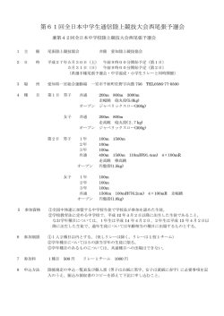
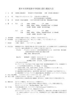
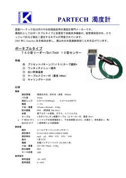
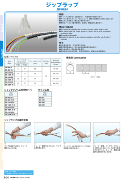
日本の 1/500 地図の精度は悪い?
-FIG 技術大会に参加しての感想-
JFS 第 5 分科会委員長
(株)パスコ 塚原 弘一
5 月にモロッコで開催された FIG 作業週間(Working Week)技術大会に参
加し、最新の Mobile Mapping System を使用した地図作成技術について発表
する機会を得た。
発表内容は、日本で開発されたシステムを用い、GPS 衛星を十分受信できな
い条件下においても適当なランドマークを設置して行うことで、公共測量作業
規程の定める 1/500 精度の測量は十分に達成可能であることを実証実験によっ
て示したものである。
発表後の質疑の中で、たぶんヨーロッパのどこかの国から参加された技術者
だと思うが、「25cm というのは本当に縮尺 1/500 の精度か?」と質問してき
たので、「あなたはこの値が 1/500 地図の精度としては大きすぎると思ってい
るのか?」と逆に聞き返すと「そのとおり。」という。各国で精度の尺度も違
うし単純に比較できない、本当に比較するにはベンチマークテストが必要であ
る、というようなことを説明したが、必ずしも納得を得られなかった。
当該セッションが終了した後にも、日本に興味があるという、モロッコの大
学でリモートセンシングを専攻している女子学生がやってきて、25cm という
値は大きすぎると言うので、「同じく精度といっても、SD や RMSE といった
表現もあるし、それぞれの国で地図の取得基準や中身も異なる、そもそも、各
国が言っている精度は建物や道路縁などの地物全体に亘った位置精度なのか、
GCP のような点での精度で言っているのかわからない。私は測量屋で実際に作
業をしているので、写真測量だけで各国が言っているような精度を出すのは疑
わしいと思っている。」などと、相手がまだ学生なのをいいことに、自分が写
真測量の経験が無いのを隠してまでも説得しようと試みた。彼女が納得してい
ないのは顔を見れば明らかであった。
実のところ、私は写真測量の専門家では無いが、地図の精度には興味を持っ
ている。先日も、たまたま、ヨーロッパ各国が地図作成や精度についてアンケ
ート調査した結果報告を見つけて調べたことがあった。それによると各国は縮
尺 1/500~1/2500 の地図を写真測量方式で作成しており、近年はデジタル化が
進められている。縮尺 1/1000 に限って地図精度を見ると、その値は多くは 20
~30cm 程度であり、日本に比べると格段に良い値が書かれてあった。わずか
にイギリスとドイツが日本の値と比較できる程度の値を示しているが、それと
て日本よりは少し値が良かったと思う。してみると、今回、彼らが「1/500 の
地図精度が 25cm というのは本当か?」と聞いてくるのは、しごく当然のこと
であった。
ここに至って、縮尺 1/500 に限らず、地図の精度は世界でどうなっているの
か、日本の地図や測量の内容や手法は独自の進化を遂げた、いわゆる「ガラパ
ゴス状態」になっていないのか、という心配が頭をもたげてきた。
まず、日本の公共測量成果である地図は、本当のところどの程度の精度があ
るのか、が検証されねばならない。これは 10 年以上も前の話なので、現在の
状況に合っていないかも知れないが、ある調査業務の中で、1/500、1/1000、
1/2500 の公共測量成果について、表現された地物(道路及び建物)の座標を
GPS 測量で実測した値と比較したことがあった。この結果、それぞれ水平位置
で 25cm、75cm、175cm としている要求精度について、平均値からのばらつき
(SD)として見て、1/500 の要求精度は実測で補わなければ実現困難なこと、
1/1000 では要求精度とほぼ見合っていること、逆に 1/2500 では、実際の地図
の方が精度良く作成されていた。これは数少ないサンプルによる結果であった
が、最近では、ネットワーク型 RTK-GPS などによって大量の検証点座標が取
得できる状況なので、今こそ、きちんとした精度検証が行われるべきではない
かと思う。
また、公共測量の地図作成における要求精度はどのようにして決められたの
かということも今一度明らかにするべきだし、デジタル地図の時代に合わせて、
もし必要ならば見直すことも必要であろう。聞くところによれば、現行の地図
精度は、地図上での描画精度が原型になっていて、地図上で許容される転移の
量などがその根拠になっているとのこと。
一方で、最近は地図作成のデジタル化が進み、各作成工程での許容精度も細
かく規定され、例えば数値図化工程では、標定点で地上測量との座標差の許容
誤差が縮尺 1/500、1/1000、1/2500 でそれぞれ 15cm、30cm、75cm を標準と
するなど相当に厳しい精度を課している。このような小さな誤差で標定された
写真画像から得られる最終的な地図成果もヨーロッパ各国の言うような精度を
有していても良さそうである。
言いたいことはこうである。我々日本の測量業界が測量の技術、システムあ
るいはノウハウを持って世界に出て行こうとする時に(これは政府が我々業界
に要求している話である)、今のような状況では始めから全く相手にされない
ので、官民挙げてこの誤解を解く努力をしていかないといけないと言うことで
ある。もしかすると、誤解でも何でもなくて、我々日本の地図精度は諸外国に
比べて本当に悪いのかも知れない。
The Development of Accuracy Maintenance Method
for Mobile Mapping System (MMS) Data
at GPS Invisible Area
Akihisa Imanishi, Kikuo Tachibana
& Koichi Tsukahara
PASCO CORPORATION
© PASCO CORPORATION 2010
Mobile Mapping System
High accurate 3D measurements
Very dense imagery & laser points
Easy & Safety operation
MMS (TYPE-S)
© PASCO CORPORATION 2010
FIG Working Week 2011
Bridging the Gap between Cultures
Marrakech, Morocco, 18‐22 May 2011
-1-
1
MMS Sensor-unit installed on Vehicle
MMS (Type-X)
Odometer
-2-
© PASCO CORPORATION 2010
MMS Specifications
Spec Item
Laser
Pulse Rate
Scanner Range
Scanning
Sweep angle
Camera Pixel
Shot interval
System
Laser Scanner
Camera
Vehicle
Accuracy Planimetric
Data
Vertical
Data capacity
Imagery data
© PASCO CORPORATION 2010
FIG Working Week 2011
Bridging the Gap between Cultures
Marrakech, Morocco, 18‐22 May 2011
MMS-X
13,500 points per second
80 m
75 per second
180 degrees
5 Megapixels(2400x2000)
Up to 10 shots per second
MMS-S
2 Megapixels(1600x1200)
Up to 11 shots per second
0,2,4 (selective)
0,2 (selective)
0,2,4,6 (selective)
0,2 (selective)
Volkswagen Golf Touran
TOYOTA Alphard Hybrid
Within 10 cm rms (absolute)
Within 1 cm rms (relative)
Within 15 cm rms (absolute)
Up to 8 hours
Up to 90,000 shots/camera
-3-
2
MMS Data Processing Flow
GPS
GEONE
T
FKP
Correction
GPS
Service Center
PADMS-Solid
Maps
IMU
Odometer
Lider
Camera
Data
Accumulation
Positioning 3D
Processing Rendering
Measured
Data
Recognition
Processing
OrthoImagery
Positions of
Objects
In-Vehicle equipment
Post-Processing
-4-
© PASCO CORPORATION 2010
In-Lab Processing
Positioning Processing
Distance measurement
by Odometer
Position and orientation
measurement by IMU (100Hz)
Position and orientation
GPS/IMU/Odometer
Integration adjustment
(FKP method)
Positioning by GPS (1Hz)
Orientation by GPS-Gyro
© PASCO CORPORATION 2010
FIG Working Week 2011
Bridging the Gap between Cultures
Marrakech, Morocco, 18‐22 May 2011
-5-
3
Performance of MMS surveying
Public Mapping project at
TOYONAKA
for 1/500 scale map
残差分布
0.5
0.4
0.3
0.2
0.1
-0.5 -0.4 -0.3 -0.2 -0.1
0.0
-0.1
0.0
0.1
0.2
0.3
0.4
0.5
-0.2
-0.3
-0.4
-0.5
Certification of the authorized
public survey result issued by
By using MMS,
GSI
Reduce cost and time of surveying tasks drastically
Reduce risks of accident and/or trouble during field
works
-6-
© PASCO CORPORATION 2010
Problems at Satellite Invisible Areas
Distance measurement
by Odometer
Position and orientation
measurement by IMU (100Hz)
Position and orientation
Large Position Error !
GPS/IMU/Odometer
Integration adjustment
Positioning by GPS (1Hz)
Orientation by GPS-Gyro
© PASCO CORPORATION 2010
FIG Working Week 2011
Bridging the Gap between Cultures
Marrakech, Morocco, 18‐22 May 2011
LAND MARK UPDATE METHOD
-7-
4
Land Mark Update Method
(1) 3D Coordinates of GCP
(Observed by GPS and/or TS)
(2) Land Mark Point Coordinates
(From the original measurement data)
(5)Correction of MMS
vehicle trajectory
(3) Position Correction Vector
(Difference between the GCP and the
landmark coordinates)
Vehicle Position of
original
MMS measurement data
(4)Corrected vehicle position
by adding position correction vector
© PASCO CORPORATION 2010
-8-
Outlines of Researches
Accuracy Investigation with LMU Method
Objective :
to make clarify the characteristics and accuracy of LMU Method, by
① Estimation of the accuracy by EPE
② Accuracy Investigation at Check Points
Optimal Assignment of Land Marks
to develop optical assignment method of land marks to maintain the
required accuracy for mapping scale of 1/500
Accuracy Investigation of Mapping Data
to check the accuracy of mapping results adjusted by LMU method
Estimated Posterior Error (EPE) :
Estimated error of position coordinates calculated in the positioning
processing by using kalman filter with GPS data, IMU data and
odometer data.
© PASCO CORPORATION 2010
FIG Working Week 2011
Bridging the Gap between Cultures
Marrakech, Morocco, 18‐22 May 2011
-9-
5
Accuracy Investigation with LMU Method
Test Sites
b
a c
TOYONAKA CITY
© PASCO CORPORATION 2010
b) Ell-curve section
- 10 -
a) Straight section
c) Longitudinal slope section
Accuracy Investigation with LMU Method
Land Marks and Check Points
selected to identify clearly in the
imagery captured by MMS;
Corners of parcel lines
Manholes
Corners or edges of gutters
Outline of Field measurement (Average vehicle speed :40km/h)
Test
Field
Measurement
Date
Route
straight section
TOYONAKA 18.Dec.2009 ell-curve section
CITY
longitudinal
slope section
© PASCO CORPORATION 2010
FIG Working Week 2011
Bridging the Gap between Cultures
Marrakech, Morocco, 18‐22 May 2011
Measurement Estimated Posterior
Time
Error(EPE)
13 :07 :47 ~
13 :08 :23
12 :50 :02 ~
12 :51 :15
10 :35 :58 ~
10 :37 :32
1.718m
1.710m
2.390m
- 11 -
6
Estimation of the accuracy by EPE
a) Straight section
b) Ell-curve section
c) Longitudinal slope section
EP
E
before
150m interval
100m interval
50m interval
- 12 -
© PASCO CORPORATION 2010
25m interval
Characteristics of EPE distribution
2.5
before
150m interval
100m interval
50m interval
25m interval
2
1.5
Estimated poteriori error(m)
Estimated poteriori error(m)
2.5
1
0.5
0
50
100
150
200
250
2
inflection point
1
0.5
0
300
(a) straight section
ell-curve
Difference of elevation(m)
Estimated poteriori error(m)
0.5
150
200
(b) ell-curve section
250
300
Additional distance(m)
© PASCO CORPORATION 2010
FIG Working Week 2011
Bridging the Gap between Cultures
Marrakech, Morocco, 18‐22 May 2011
200
250
300
Difference of elevation
14
1
100
150
16
1.5
50
100
(c) longitudinal slope section
before
150m interval
100m interval
50m interval
25m interval
2
0
50
Additional distance(m)
Additional distance(m)
2.5
of slope
1.5
before
150m interval
100m interval
50m interval
25m interval
Inflection point
of slope
12
10
8
6
4
2
0
Inflection point
of slope
50
100
150
200
250
longitudinal section profile
300
Additional distance(m)
- 13 -
7
Accuracy Investigation at Check Points
Check Points are settled on the halfway of the land marks
3D Residual =
Route
(Coord. on MMS cloud data)
-(Coord. by GPS/TS)
straight
section
ell-curve
section
longitudinal
slope section
Check points for investigation
Check
Point
Before
150m
interval
100m
interval
50m
interval
25m
interval
1-1
1-2
1-3
1-5
1-6
1-7
1-9
1-10
1-11
2-3
2-4
2-5
2-7
2-8
2-9
2-11
2-12
2-13
3-3
3-4
3-5
3-7
3-8
3-9
3-11
3-12
3-13
0.391m
0.300m
0.243m
0.215m
0.209m
0.308m
0.577m
0.679m
0.656m
0.297m
0.241m
0.061m
0.178m
0.166m
0.181m
0.305m
0.494m
0.518m
0.628m
0.756m
0.787m
0.568m
0.363m
0.189m
0.289m
0.390m
0.395m
0.197m
0.129m
0.109m
0.070m
0.015m
0.046m
0.067m
0.074m
0.075m
0.113m
0.189m
0.115m
0.094m
0.082m
0.095m
0.054m
0.168m
0.073m
0.054m
0.162m
0.209m
0.101m
0.077m
0.070m
0.176m
0.140m
0.066m
0.167m
0.077m
0.057m
0.029m
0.064m
0.073m
0.003m
0.006m
0.044m
0.097m
0.179m
0.079m
0.056m
0.099m
0.038m
0.046m
0.155m
0.079m
0.014m
0.041m
0.039m
0.025m
0.038m
0.041m
0.124m
0.087m
0.039m
0.099m
0.018m
0.029m
0.028m
0.005m
0.032m
0.010m
0.013m
0.055m
0.113m
0.046m
0.097m
0.077m
0.071m
0.040m
0.050m
0.007m
0.040m
0.030m
0.041m
0.026m
0.027m
0.027m
0.031m
0.075m
0.036m
0.057m
0.030m
0.003m
0.007m
0.024m
0.008m
0.032m
0.006m
0.025m
0.042m
0.012m
0.021m
0.074m
0.023m
0.051m
0.014m
0.017m
0.059m
0.022m
0.031m
0.007m
0.030m
0.020m
0.047m
0.076m
0.040m
0.025m
0.048m
- 14 -
© PASCO CORPORATION 2010
Residuals of Coordinates at Check Points
0.800
before
before
0.700
150m interval
100m interval
0.600
0.500
Residuals of Laser P oint(m)
Residuals of Laser Point(m)
0.700
50m interval
25m interval
0.400
0.300
0.200
0.100
150m interval
100m interval
0.600
50m interval
25m interval
0.500
0.400
0.300
0.200
0.100
0.000
1-1
1-2
1-3
1-5
1-6
1-7
1-9
1-10
1-11
(a) straight section
Check Point
0.000
3-3
3-4
3-5
3-7
3-8
3-9
3-11
3-12
3-13
(b) ell-curve section
Check Point
0.600
before
Residuals of Laser Point(m)
0.500
150m interval
100m interval
50m int erval
0.400
25m int erval
0.300
0.200
0.100
0.000
2-3
2-4
2-5
2-7
2-8
2-9
2-11
2-12
2-13
(c) longitudinal slope section - 15 Check Point
© PASCO CORPORATION 2010
FIG Working Week 2011
Bridging the Gap between Cultures
Marrakech, Morocco, 18‐22 May 2011
8
Optimal Assignment of Land Marks
(1) ell-curve section
Estimated poteriori error(m)
2.5
before
100m interval
100m interval+2-12
2
1.5
1
0.5
0
50
100
150
200
250
300
Additional distance(m)
EPE Distribution (100m interval)
0.180
100m interval
Residuals of Laser Point(m)
0.160
EP
E
100m interval + 2-12
0.140
0.120
0.100
0.080
0.060
0.040
0.020
0.000
2-3
2-4
2-5
2-7
2-8
2-9
2-11
2-12
2-13
Check Point
3D Residual at Check Point
EPE Distribution (100m interval + 2-12)
- 16 -
© PASCO CORPORATION 2010
Optimal Assignment of Land Marks
2.5
Estimated poteriori error(m)
(2) longitudinal slope section
before
100m interval
100m interval+3-12
2
1.5
1
0.5
0
50
100
150
200
250
300
Additional distance(m)
EPE Distribution (100m interval)
0.140
0.120
Residuals of Laser Point(m)
100m interval
EP
E
100m interval + 3-12
0.100
0.080
0.060
0.040
0.020
0.000
3-3
© PASCO CORPORATION 2010
FIG Working Week 2011
Bridging the Gap between Cultures
Marrakech, Morocco, 18‐22 May 2011
3-4
3-5
3-7
3-8
3-9
3-11
3-12
3-13
3D Residual at Check Point
Check Point
EPE Distribution (100m interval + 3-12)
- 17 -
9
Optimal Assignment of Land Marks
Optimal Assignment Method of Land Marks for GPS
Invisible Area for MMS
Route
Optimal Assignment Method of Land
Marks
Straight section
100m intervals
Ell-curve section
100m intervals and additional points near
ell-curve
100m intervals and additional points at
inflection point
Longitudinal
slope section
© PASCO CORPORATION 2010
- 18 -
Accuracy Investigation of Mapping Data
-0.3
Res_Y(Unit in M)
-0.2
-0.1
-0.3
-0.2
-0.1
0.0
0.1
0.2
0.3
0.0
0.1
0.2
0.3
Res_X(Unit in M)
Distribution of mapping point residuals
Mapping point identification by
using PADAMS-Solid
MMS data adjusted by
LMU method have
adequate accuracy for the
official mapping project !
© PASCO CORPORATION 2010
FIG Working Week 2011
Bridging the Gap between Cultures
Marrakech, Morocco, 18‐22 May 2011
Res_X
Res_Y
Planimetric
RMS
0.074m
0.070m
0.102m
MAX
0.217m
-0.242m
Reference Value
0.242m
0.250m
- 19 -
10
Conclusions and Future Works
Accuracy of MMS data maintenance method at GPS invisible areas
was investigated.
We conclude,
In case of standard data capture speed of 40km/h, 100m
interval of land marks is sufficient.
Additional land mark at inflection point (horizontal curve and
slope) is effective to improve laser point cloud data accuracy.
1/500 scale mapping by MMS is available even under GPS
invisible area.
Optimal assignment method of land mark is useful for mapping
of tunnels and other difficult areas for observation.
In order to examine more effective methods of assignment, it will be
necessary to take into account of vehicle velocity as our future work.
© PASCO CORPORATION 2010
- 20 -
Thank You
http://www.pasco.co.jp/
© PASCO CORPORATION 2010
FIG Working Week 2011
Bridging the Gap between Cultures
Marrakech, Morocco, 18‐22 May 2011
- 21 -
11
© Copyright 2026 Paperzz