7mm角コードスイッチのシリーズ拡充、端子配列のバリエーションUP
サーフェイスマウントタイプ
SH-7000
DIP型ロータリコードスイッチ
ROTARY CODED SWITCHES (SMD)
RoHS 指令対応 RoHS compliant
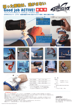
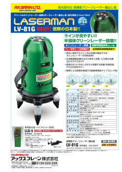
内部構造図 INTERNAL STRUCTURE
①
②
④
ス
イ
ッ
チ
③
⑧
⑨
⑦
⑤
名 称
①
■特 長 FEATURES
②
● RoHS指令対応
● コモン端子を中央に配置
● 良好な視認性
● グレイコード出力をバリエーション
● 洗浄可能
③
● RoHS compliant
● Center Common terminal pins location
● High digit visibility
● Gray code output available
● Washable
⑥
材 料
Part name
マーキングカバー
Marking cover
Material
ステンレス
Stainless steel (SUS 304)
ステンレス
カバー
シリコンゴム
Silicone rubber
④
ロータ
PPS(ポリフェニレンサルファイド)
Rotor
Polyphenylenesulphide
⑤
スペーサー
⑥
可動接点
⑦
固定接点
⑧
ハウジング
⑨
端子
Moving contact
ステンレス
銅合金、金めっき
Housing
PPS(ポリフェニレンサルファイド)
Polyphenylenesulphide
銅合金、金めっき
Terminal pin
Copper alloy, Gold-plated
端子形状 Shape of terminal
Without knob (Minus slot)
包装形態 Form of packaging
1:10ポジション リアルコード
3:10ポジション コンプリメンタリコード
4:10ポジション グレイコード
5:16ポジション リアルコード
7:16ポジション コンプリメンタリコード
8:16ポジション グレイコード
T :テーピング
(リール)
M:マガジン
10 positions, real code
10 positions, complementary code
10 positions, gray code
16 positions, real code
16 positions, complementary code
16 positions, gray code
—
Copper alloy, Gold-plated
A:J-リード
J-hook
B:ガル・ウィング
Gull wing
C:スルーホールピン Through hole pins
Code format
UL-94V-0
Fixed contact
シリーズ名 Series name
コードフォーマット
UL-94HB
Stainless steel (SUS 304)
Spacer
S H - 7 0 1 0 T A
0:つまみ無し
(マイナス溝)
—
Stainless steel (SUS 301)
Cover
“O”リング
“O” ring
■型式表示 PART NUMBER DESIGNATION
ロータ形状 Shape of rotor
燃焼性
Flammability
設定方向 Setting position
0:上部設定型 Top setting
※ご注文に際しては、型式一覧表をご確認ください。
Please refer to the LIST OF PART NUMBERS when placing orders.
A-128
䂓᭽䈲ᡷༀ䈱䈢䉄ᄌᦝ䈘䉏䉎႐ว䈏䈅䉍䉁䈜䇯㩷㩷㩷㪪㫇㪼㪺㫀㪽㫀㪺㪸㫋㫀㫆㫅㫊㩷㪸㫉㪼㩷㫊㫌㪹㫁㪼㪺㫋㩷㫋㫆㩷㪺㪿㪸㫅㪾㪼㩷㫎㫀㫋㪿㫆㫌㫋㩷㫅㫆㫋㫀㪺㪼㪅
Taping (Reel)
Magazine
UL-94V-0
—
SH-7000
ROTARY CODED SWITCHES (SMD)
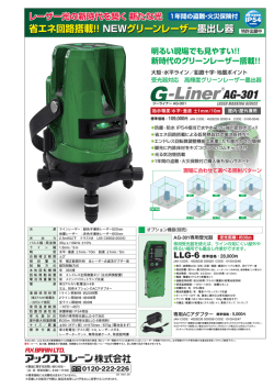
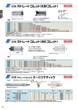
■コードフォーマット CODE FORMAT
16 positions
No. of positions
Position
0
1
2
3
4
5
6
7
●
●
●
●
●
●
8
Real code
4
●
2
●
1
Code
●
●
8
●
●
●
●
Complemen-
4
●
●
●
●
tary code
2
●
●
1
●
●
●
●
●
●
●
●
2
●
1
●
●
●
●
●
A
B
C
D
E
F
●
●
●
●
●
●
●
●
●
●
●
●
●
●
●
●
●
●
●
●
●
●
●
●
9
●
●
●
4
8
●
●
●
●
●
●
8
Gray code
ス
イ
ッ
チ
10 positions
●
●
●
●
●
●
●
●
●
●
●
●
●
●
●
●
●
●
●
●
●
●
●
●
●
●
●
●
●
● …Contact closed
■型式一覧表 LIST OF PART NUMBERS
設定方向
ロータ
端子形状
包装形態
Setting
position
Shape of
rotor
Shape of
terminal
Form of
packaging
2進化10進
SH-7010TA
SH-7010MA
上部設定 マイナス溝 B(ガル・ウィング) テーピング Taping SH-7010TB
Top setting Minus slot
マガジン Magazine SH-7010MB
Gull wing
A(J-リード)
J-hook
テーピング Taping
C(スルーホールピン)
Through hole pins
テーピング Taping
マガジン Magazine
マガジン Magazine
SH-7030TA
SH-7050TA
SH-7030MA
SH-7050MA
SH-7030TB SH-7040TB SH-7050TB
SH-7030MB SH-7040MB SH-7050MB
SH-7010MC SH-7030MC
:製作不可能
テーピング及びマガジン仕様は、切り売りしませんので、リール及
びマガジン単位でご注文をお願いします。
■標準仕様
保存温度範囲
BCD
(Real code, Complementary code, Gray code)
BCH
(Real code, Complementary code, Gray code)
接点定格
− 40 ~ 85 °C
− 40 ~ 105 °C (Gray code)
接触抵抗
Contact rating
Non-switching
Switching
Minimum
Contact resistance
絶縁抵抗
Storage temperature range
Insulation resistance
洗浄可能
シール性
Sealing
質 量
Net weight
SH-7050MC SH-7070MC
500 pcs./reel
50 pcs./stick
500 pcs./reel
50 pcs./stick
50 pcs./stick
ELECTRICAL CHARACTERISTICS
使用温度範囲
Operating temperature range
SH-7070TA
SH-7070MA
SH-7070TB SH-7080TB
SH-7070MB SH-7080MB
■電気的特性
STANDARD SPECIFICATIONS
Circuit type
包装数量
: Not manufactured
※ Verify the above part numbers when placing orders.Taping and
magazine version can be supplied only in reel or stick unit.
※ご注文に際しては、上記型式をご確認ください。
回路構成
2進化16進
Binary coded decimal
Binary coded hexadecimal
Pieces in
リアルコード コンプリメンタリコード グレイコード リアルコード コンプリメンタリコード グレイコード
package
Real code Complementary code Gray code Real code Complementary code Gray code
耐電圧
Washable by "O" ring
※詳細はA-218、A-219をご覧下さい。
※Please refer to A-218, A-219
Dielectric strength
Approx. 0.38 g
A-129
䂓᭽䈲ᡷༀ䈱䈢䉄ᄌᦝ䈘䉏䉎႐ว䈏䈅䉍䉁䈜䇯㩷㩷㩷㪪㫇㪼㪺㫀㪽㫀㪺㪸㫋㫀㫆㫅㫊㩷㪸㫉㪼㩷㫊㫌㪹㫁㪼㪺㫋㩷㫋㫆㩷㪺㪿㪸㫅㪾㪼㩷㫎㫀㫋㪿㫆㫌㫋㩷㫅㫆㫋㫀㪺㪼㪅
DC50 V 100 mA
DC5 V 100 mA
DC20 mV 1 μA
100 mΩ maximum
1000 MΩ (DC100 V) minimum
AC250 V, 60 s
SH-7000
ROTARY CODED SWITCHES (SMD)
■機械的特性
■環境特性
MECHANICAL CHARACTERISTICS
ポジション数
回転トルク
Adjustment torque
ENVIRONMENTAL CHARACTERISTICS
10, 16
No. of positions
3 ~ 20 mN·m { 3~ 204 gf·cm} maximum
Vibration
36° (10 positions)
22.5° (16 positions)
耐衝撃性
ステップ角度
Stepping angle
はんだ付け性
Humidity
High temperature exposure
耐寒性
Thermal shock
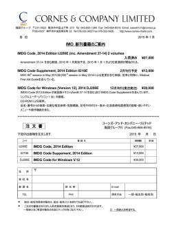
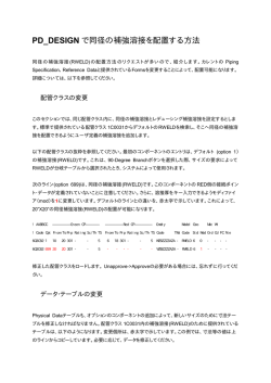
〈はんだ耐熱性評価用リフロープロファイル Reflow profile for soldering heat evaluation〉
5 N {0.51 kgf} 10 s
(°C)
250
5 N {0.51 kgf} 10s
200
Pull-off strength
{ } : 参考値 Reference only
Temperature
Width 90 mm, bend 3 mm, 5 s, 1 time
引きはがし強さ
−40 (0.5 h) ~ 85 °C ( 0.5 h ), 5 cycles
−40 (0.5 h) ~ 105 °C ( 0.5 h ), 5 cycles (Gray code)
温度サイクル
:
Manual soldering:
350 ± 10 °C, 3 ~ 4 s
Substrate bending
− 40 °C, 96 h
Low temperature exposure
手はんだ
耐基板曲げ性
85 °C, 96 h
105 °C, 96 h (Gray code)
耐熱性
Peak temperature 255 °C
(Please refer to the profile below.)
Shear (adhesion)
40 °C, 相対湿度 Relative humidity 90 ~ 95 %,
240 h
耐湿性
リフロー Reflow:255 °C (Peak temperature)
(詳細は下記プロファイル参照)Reflow
10000 steps minimum, DC5 V, 100 mA
Load life
Flow : 260 ± 3 °C as the temperature in
a pot of molten solder, immersion from head of terminal to
backside of board,5 ~ 6 s, two
times maximum
固着性
490 m/s2, 11 ms
6 directions for 3 times each
耐久性
フロー:260 ± 3 °Cの槽内に端子先
端から基板の裏面まで5∼6
秒間浸漬を2回
Soldering heat
10-500-10 Hz, 3 directions for 2 h each
Shock
245 ± 3 °C, 2 ~ 3 s
Solderability
はんだ耐熱性
振幅 (Amplitude) 1.5 mm(全振幅)or
2
加速度 (Acceleration) 98 m/s ,
耐振性
+5
0
°C
Over 230 °C
Peak : 250
Pre Heating Zone
180 °C
150 °C
150
90 ± 30 s
100
30 ± 10 s
50
Soldering Zone
Heating time
リフロー回数:2回 Reflow : two times maximum
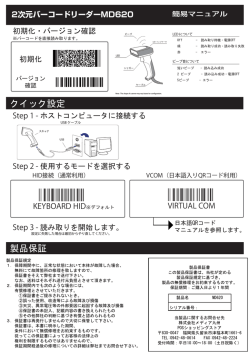
■外形寸法図 OUTLINE DIMENSIONS
● SH-7010A (Real code)
● SH-7030A (Complementary code)
Unless otherwise specified, tolerance: ± 0.3 (Unit: mm)
● SH-7010B (Real code)
● SH-7030B (Complementary code)
製造年月記号
Production date code
製造年月記号
Production date code
7.3
6 – 0.6
t = 0.15
2.54
10
2.54
0.7 W × 2.8 L × 1 D
② Ⓒ ⑧
0.7 W × 2.8 L × 1D
コンプリメンタリコードのみ表示
Marking appears only with complementary code
3.75
コンプリメンタリコードのみ表示
Marking appears only with complementary code
A-130
䂓᭽䈲ᡷༀ䈱䈢䉄ᄌᦝ䈘䉏䉎႐ว䈏䈅䉍䉁䈜䇯㩷㩷㩷㪪㫇㪼㪺㫀㪽㫀㪺㪸㫋㫀㫆㫅㫊㩷㪸㫉㪼㩷㫊㫌㪹㫁㪼㪺㫋㩷㫋㫆㩷㪺㪿㪸㫅㪾㪼㩷㫎㫀㫋㪿㫆㫌㫋㩷㫅㫆㫋㫀㪺㪼㪅
0.65 min.
3.75
7.1
7.5
② Ⓒ ⑧
④ Ⓒ ①
5.1
④ Ⓒ ①
6 – 0.6
t = 0.15
0.65 min.
7.3
7.1
ス
イ
ッ
チ
2.54
2.54
SH-7000
ROTARY CODED SWITCHES (SMD)
■外形寸法図 OUTLINE DIMENSIONS
● SH-7010C (Real code)
● SH-7030C (Complementary code)
Unless otherwise specified, tolerance: ± 0.3 (Unit: mm)
● SH-7050A (Real code)
● SH-7070A (Complementary code)
ス
イ
ッ
チ
製造年月記号
Production date code
7.3
製造年月記号
Production date code
④ Ⓒ ①
3.5 ± 1
2.54
5.1
3.7
0.7 W × 2.8 L × 1 D
7.5
② Ⓒ ⑧
6 – 0.6
t = 0.15
④ Ⓒ ①
7.1
7.1
7.62 ± 0.5
7.3
2.54
コンプリメンタリコードのみ表示
Marking appears only with complementary code
② Ⓒ ⑧
3.75
2.54
2.54
0.7 W × 2.8 L × 1 D
6 – 0.6
t = 0.15
コンプリメンタリコードのみ表示
Marking appears only with complementary code
● SH-7050B (Real code)
● SH-7070B (Complementary code)
● SH-7050C (Real code)
● SH-7070C (Complementary code)
製造年月記号
Production date code
7.3
0.65 min.
製造年月記号
Production date code
② Ⓒ ⑧
10
7.1
7.1
④ Ⓒ ①
④ Ⓒ ①
6 – 0.6
t = 0.15
7.62 ± 0.5
7.3
0.7 W × 2.8 L × 1 D
3.7
3.5 ± 1
2.54
2.54
② Ⓒ ⑧
0.7 W × 2.8 L × 1 D
3.75
0.65 min.
コンプリメンタリコードのみ表示
Marking appears only with complementary code
2.54
2.54
6 – 0.6
t = 0.15
コンプリメンタリコードのみ表示
Marking appears only with complementary code
● SH-7040B (Gray code)
● SH-7080B (Gray code)
製造年月記号
Production date code
10
⑧
0.7 W × 2.8 L × 1 D
3.75
0.65 min.
②
Ⓒ
0.65 min.
④
①
②
5.08
2.54
5 – 0.8
t = 0.15
10
①
2.54
7.1
Ⓒ
7.1
④
2.54
⑧
0.7 W × 2.8 L × 1 D
A-131
䂓᭽䈲ᡷༀ䈱䈢䉄ᄌᦝ䈘䉏䉎႐ว䈏䈅䉍䉁䈜䇯㩷㩷㩷㪪㫇㪼㪺㫀㪽㫀㪺㪸㫋㫀㫆㫅㫊㩷㪸㫉㪼㩷㫊㫌㪹㫁㪼㪺㫋㩷㫋㫆㩷㪺㪿㪸㫅㪾㪼㩷㫎㫀㫋㪿㫆㫌㫋㩷㫅㫆㫋㫀㪺㪼㪅
3.75
0.65 min.
0.65 min.
7.3
製造年月記号
Production date code
7.3
5 – 0.8
t = 0.15
5.08
2.54
SH-7000
ROTARY CODED SWITCHES (SMD)
■推奨ランドパターン RECOMMENDED P.C.B. PAD OUTLINE DIMENSIONS
● A type
ス
イ
ッ
チ
● B type
● Gray code
(Unit: mm)
2.5
0
1
5.08
1
5.08
0
1
0
3
5.08
3
9
11
11
注)0点は搭載中心とする
Note) The zero point is the center of mounting.
■端子接続/プリント基板加工寸法
TERMINAL CONNECTION / P.C.B. THROUGH HOLE DIMENSIONS
(Unit: mm)
上部設定型(スルーホール)
Top setting (Through hole)
端子接続図
(裏面図)
Terminal pin
layout
(Bottom view)
Real code
8
C
2
Complementary code
8
C
2
1
C
4
プリント基板
加工寸法
(反対面から見た図)
P.C.B. dimensions
(Bottom view)
6 – φ 1 hole
2.54 ± 0.1
2.54 ± 0.1
1
C
4
SH-7000 case
■PACKAGING SPECIFICATIONS
■包装仕様
<Taping packaging specifications>
〈テーピングの包装仕様〉
● テーピングは500個/リール単位の包装になりますので、500
● Taping version is packaged in 500 pcs. per reel.
Orders will be accepted for units of 500 pcs., i.e., 500,
1000, 1500, pcs., etc.
● Taping version is boxed with one reel (500 pcs.).
個単位
(500個、1000個、1500個…)
でのご注文をお願い致
します。
● テーピングリールの箱詰めは、1リール
(500個)
ごとに製品箱
に包装致します。
Maximum number of consecutive missing pieces = 2
Leader length and reel dimension are shown in the
diagrams below:
製品の脱落は、連続2個以内と致します。
テープのリーダ部、空部およびリール寸法は図に示します。
A-132
䂓᭽䈲ᡷༀ䈱䈢䉄ᄌᦝ䈘䉏䉎႐ว䈏䈅䉍䉁䈜䇯㩷㩷㩷㪪㫇㪼㪺㫀㪽㫀㪺㪸㫋㫀㫆㫅㫊㩷㪸㫉㪼㩷㫊㫌㪹㫁㪼㪺㫋㩷㫋㫆㩷㪺㪿㪸㫅㪾㪼㩷㫎㫀㫋㪿㫆㫌㫋㩷㫅㫆㫋㫀㪺㪼㪅
SH-7000
ROTARY CODED SWITCHES (SMD)
● テープのリーダ部および空部 Embossed tape dimensions
● リールの寸法図
Reel dimensions
(Unit: mm)
(JIS C 0806-3に一致 Conforms to JIS C 0806-3)
(EIAJ ET-7200Aに準拠 In accordance with EIAJ ET-7200A)
製品装着部
Filled
空部
Empty
2 ± 0.5
終り
End
q 13 ± 0.2
始め
Head
40 mm min.
引き出し方向
Direction of feed
q 21 ± 0.8
20 pitches min.
リーダ部 Leader
400 mm min.
製品表示ラベル
Part No. label
q 330 ± 2
空部
Empty
q 100 ± 1
25.4 ± 1
29.4 ± 1
● SH-70□0TA
● SH-70□0TB
1.75 ± 0.1
(Unit: mm)
12 ± 0.1
0.4 ± 0.1
11.5 ± 0.1
4 ± 0.1
2 ± 0.1
23
24
456
901
q 1.5
+0.1
0
78
4.3
引き出し方向
Direction of feed
■包装仕様
■PACKAGING SPECIFICATIONS
<Magazine packaging specifications>
〈マガジンの包装仕様〉
● マガジンは各スティック単位でのご注文をお願い致します。
● Please order the multiple numbers of the specific
packing quantities.
Pieces in package : 50 pcs./stick
包装数量:50個/スティック
● マガジン寸法図 Magazine dimensions
(Unit : mm)
17.2
13.4
マガジンの長さ:390±3mm
magazine length:390±3mm long
A-133
䂓᭽䈲ᡷༀ䈱䈢䉄ᄌᦝ䈘䉏䉎႐ว䈏䈅䉍䉁䈜䇯㩷㩷㩷㪪㫇㪼㪺㫀㪽㫀㪺㪸㫋㫀㫆㫅㫊㩷㪸㫉㪼㩷㫊㫌㪹㫁㪼㪺㫋㩷㫋㫆㩷㪺㪿㪸㫅㪾㪼㩷㫎㫀㫋㪿㫆㫌㫋㩷㫅㫆㫋㫀㪺㪼㪅
ス
イ
ッ
チ
© Copyright 2026 Paperzz