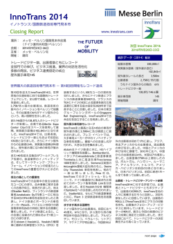
ROLLER GUIDE Linear motion products 直線運動ローラー軸受の開発経緯 当社では1963年(昭和38年)よりプリント基板用の小径超硬工具の製造・販売を 始めました。 社内専用機を自社で開発・製造していた当社では、それらに組込まれる クロスドローラーガイドを1975年(昭和50年)、国内で最初に商品化し、現在に至 るまで国内相当量のシェアを確保しています。特に他社に無い高精度級(SF級)で は、光学、測定、医療などの業界でも大変多くのお客様に親しまれております。 また、クロスドローラーガイドの無限軌道化についてのユーザー希望を実現するべ く、転動体にローラーを使用する形式での無限軌道軸受の開発研究を行ってきまし た。その過程ではクロスドローラーガイドのゲージを無くしたローラー総詰めタイプ での試作も試みましたが、ローラーの相互接触による弊害を考慮し、高精度直線ロー ラー軸受としては不適切であると判断致しました。 この様にして長年研究する中で現在商品化したローラーをチェーン形式で支える構 造を開発し、1984年(昭和59年)、トルーガイドを晴海の国際工作機械見本市で発 表致しました。この形式は他社に類を見ない独創的な構造をしており、転動体にロー ラーを使用している為、レールの転動面を平面研削でき、高精度でボールタイプと比 べ接触面積が広く、高剛性を得ることができます。この考え方をクロスドローラーガ イドにも応用し、クロスローラー方式のチェーンリンクでの保持方法を開発しクロス ドローラーガイド無限軌道タイプ(RGH)を開発致しました。 This linear motion system is based on the well known crossed roller design. A high level of High rigidity is achieved through a geometric design that permits a tight pitchand nearly 100% use of the roller length. The truly optimal interface of roller and cage reduces drag to a minimum and allows fully stick-slip free, high precision positioning and rapid stroke movement without heat build-up. 目 次 Contents 製品案内 クロスドローラーガイドの特長 Products Features of linear crossed roller guides ガイドレールG型 P3/P4 P5/6 Guide Rail Type G ガイドレールG型 ローラー個数/質量 P7 Roller quantity/mass of guide rail type G ガイドレールGW型 P8 Guide rail type GW ガイドレールGW型 ローラー個数/質量 P9 Roller quantity/mass of guide rail type GW ガイドレールGS型 P10 Guide rail type GS ガイドレールGV型 P11 Guide rail type GV 無限軌道タイプRGH型 P12 Unlimited stroke type RGH 無限軌道タイプTGH型 P13~P15 Unlimited stroke type TGH ローラーテーブルTS型・TR型・TL型の特長 P16 Features of roller tables TS型ローラーテーブル P17/P18 Roller table type TS TR型ローラーテーブル P19/P20 Roller table type TR TL型ローラーテーブル P21/P22 Roller table type TS 技術情報 直線運動軸受の選定 Technical information Selection of linear motion guide 取付側ステージの精度 P23~P25 P26 Mounting stage precision 予圧とトルク P27 Preload & Torque 有限軌道タイプG型の取付方法 P28 Assembly of G 有限軌道タイプGW型の取付方法 P29 Assembly of GW 無限軌道タイプRGH型/TGH型の取付方法 P30 Assembly of RGH/TGH type 納入状態 RG型納入状態 Delivery condition Delivery condition for the RG type RGH型納入状態 P31 P32 Delivery condition for the RGH type TGH型納入状態 P33 Delivery condition for the TGH type 精密テーブル仕様書 P34 ROLLER GUIDE 2 クロスドローラーガイド Linear crossed roller guides クロスドローラーガイドの特長 Features of linear crossed roller guides 各部名称 Components 六角穴付ボルト Socket screw 六角穴付ボルト Socket screw エンドピース End piece ガイドレール Guide rail ローラーケージ Roller cage 特 長 Features 品 質 Quality 独自のローラー保持方法により、接触長を長くする事が可能 自社開発による溝研削盤により、高精度に研磨仕上げしてお となりました。これにより高精度、長寿命が保証されます。 ります。特にローラーの案内面は、円滑な作動が出来るよう また隙間が少なくなり、ごみ等が入りにくくなっています。 に鏡面に近い特殊仕上げ法を採用しています。 Unique designed roller cage makes longer contact length possible. It also provides narrow gap between two rails. It prevents dust ingression. All products are ground accurately by unique grinding machines that are developed by Union Tool. Especially, rolling surfaces are finished like mirror. 図 1 Fig.1 従来型 Conventional design ユニオンツール型 UNION TOOL design 表 1 Table 1 仕様 Specification 従来型 Conventional design ユニオンツール型 UNION TOOL type 接触長 Contact length 接触長が長い Contact length increase double 1 1.2 剛性 Rigidity ローラーピッチ Roller pitch レール、ケージ間の隙間 Clearance between rail and cage 3 ROLLER GUIDE 剛性が大幅に向上 Rigidity is extremely increased 1 1.1 ピッチを細かくしてローラー数を増加 Make roller qty increase due to shorten roller 1 0.5 防塵と安定性 Dust proofing(or dust control)and stabillity 精 度 Precision SF(スーパーフィニッシュ)級 Super finish (SF) 下のグラフは、ガイドレールの基準面と V 溝転動面の平行 従来より品質、精度で定評のあるユニオンツールの直線ク 度を示します。 ロスドローラーガイドですが、標準級では満足できないお 部品精度の向上は、円滑・高精度の摺動が得られるのみで 客様のためにさらに高精度のSF(スーパーフィニッシュ)級 なく、直接耐用寿命の増大につながります。 を用意しています。このSF級のために、ユニオンツールは 新規に製造設備を設計製作し、他に類を見ない高精度を実 The graph below shows the maximum tolerance of the dimension between the guide rail reference surface and the raceway. The high accuracy of each part provides smoother, more precise slide movement and long service life. Tolerance of roller outer diameter is within 1μm. ●ローラーの径のバラツキは一連のケージ内で0.5μm以下 になっています。 (標準級は2μm以下。) UNION TOOL crossed Roller Guides are known for their high quality and precision. In applications demanding the highest performance, UNION TOOL offers Super Finish. To achieve this, special facilities have been created to produce a never before attained level of precision. Surface are diamond to tolerances of half that of regular precision with surface roughness of 0.1a. Fluctuation of the roller diameter is less than 0.5μm within a series of cages. (It is less than 2μm for the standard grade.) Parallelism of V-chasm surface has been improved dramatically as in the following graph. Δμ Δμ 図 3 Fig.3 G1, G2, G3 Parallelism 0.05a以下となっています。 ●V溝面の平行度はグラフのように飛躍的に向上しています。 図 2 Fig.2 (μm) 平 4 行 3 度 2 1 0 現しました。 ●ガイドレールのV溝 面の面 粗 度 が 標準 級の0.1aに比ベ 標 準 Standard SF 100 200 300(mm) レール全長 Length G4, G6 (μm) 6 Parallelism 平 行 度 標 準 Standard 4 3 2 1 SF 100 200 300 400 500 600(mm) レール全長 Length G9〜G24 ケージのズレ ケージは、極めて正確な動きをしますが、 (μm) 8 Parallelism 平 行 度 標 準 Standard 6 4 3 2 1 SF 0 100 200 300 400 500 レール全長 Length 1000 1500(mm) モーメント・垂直使用や接触の不均一及び 機械の振動等によりケージズレを生じる 事があります。ケージズレが問題となる場 合は、無限運動軸受のTGHガイドの御採 用を推奨します。 Cage shift Cage shift might be happened by moment, vertical setting, unequally touchiness on surface and machine vibration. If cage shift is a problem for your spec, we offer to use TGH. ROLLER GUIDE 4 クロスドローラーガイド Linear crossed roller guides 0 ※G1公差 -0.1 G1 tolerance ガイドレールG型 Guide rail type G P×n 硬 度 Hardness : 58〜64HRC : 58〜64HRC Rail Roller : 58 - 64HRC : 58 - 64HRC A G1 8.5 取付穴(mm) Dimensions Mounting holes C 4 0.3 E 3.9 エンドピース 組合せロー End piece ラーケージ G H J K M P T 1.8 3.0 1.2 1.65 2.0×0.4 10 1.0 Desighnated roller cage SF級設定 SF R1 SF級のみ SF only G2 12 6 0.4 5.6 2.5 4.4 2 2.55 3 15 1.5 R2 ○ G3 18 8 0.5 8.6 3.5 6 3.1 3.3 4 25 2 R3 ○ R4 ○ R6 ○ R9 ○ G4 22 11 0.8 10.6 4.5 8 4.2 4.3 5 40 2.5 G4A 24 12 0.8 11.6 5 8 4.2 4.3 5 40 2.5 G6 30 15 1.0 14.4 6 9.5 5.2 5.2 6 50 3 G6A 31 15 1.0 14.9 6 9.5 5.2 5.2 6 50 3 G9 40 20 1.2 19.3 8 10.5 6.2 6.8 8 100 3 G9A 44 22 1.2 21.3 9 10.5 6.2 6.8 8 100 3 G12 58 28 2 28 12 13.5 8.2 8.5 10 100 4 R12 ー G15 71 36 2 34.4 14 16.8 10.2 10.5 12 100 5 R15 ー G18 83 40 3 40.2 18 18.8 12.2 12.5 14 100 5 R18 ー G24 110 55 3 53.6 24 22 14.2 14.5 16 100 5 R24 ー 150 (9) 250 (9) 400 (9) 500 (9) 1000 (9) 1200 (11) 1200 (11) 1200 (11) 165 (10) 275 (10) 440 (10) 550 (10) 1100 (10) 1500 (14) 1500 (14) 1500 (14) 型 式 Model G1 G2 G3 G4 G4A G6 G6A G9 G9A G12 G15 G18 G24 長さL(n) (mm) Length L 20 (1) 30 (1) 50 (1) 80 (1) 100 (1) 200 (1) 300 (2) 300 (2) 300 (2) 400 (3) 30 (2) 45 (2) 75 (2) 120 (2) 150 (2) 300 (2) 400 (3) 400 (3) 400 (3) 500 (4) 40 (3) 60 (3) 100 (3) 160 (3) 200 (3) 400 (3) 500 (4) 500 (4) 500 (4) 600 (5) ※ G9,G9A 以上につきましては、受注生産品となります。 5 H T MはISO規格 M shows ISO standard 外形(mm) B X-X断面 section of X-X P/2 L 寸法表 Dimensions 型 式 Model M B ROLLER GUIDE 50 (4) 75 (4) 125 (4) 200 (4) 250 (4) 500 (4) 600 (5) 600 (5) 600 (5) 800 (7) 60 (5) 90 (5) 150 (5) 240 (5) 300 (5) 600 (5) 700 (6) 700 (6) 700 (6) 1000 (9) 70 (6) 105 (6) 175 (6) 280 (6) 350 (6) 700 (6) 800 (7) 800 (7) 800 (7) 1200 (11) 80 (7) 120 (7) 200 (7) 320 (7) 400 (7) 800 (7) 900 (8) 900 (8) 900 (8) 1500 (14) Model G9, G9A and bigger are build to order. 135 (8) 225 (8) 360 (8) 450 (8) 900 (8) 1000 (9) 1000 (9) 1000 (9) 180 (11) 300 (11) 480 (11) 600 (11) 1200 (11) G X T ガイドレール ローラー材 K C P P/2 J 0 A -0.300 E X ローラーケージ Roller Cage 基本定格荷重はローラー1個当り(45°荷重方向に対し)の Basic load rating is the value per 1 roller under a load at 45°. Number of pitch = Roller quantity − 1 Cz : Basic dynamic load rating for 1 roller Coz : Basic static load rating for 1 roller 値です。 ピッチの数 = ローラー数 −1 Cz : 基本動定格荷重 Coz : 基本静定格荷重 P×n+D P×n+D ℓ= P × n + D ℓ :ローラーケージ長(mm) Roller cage legth t t P P d W P :ローラーピッチ長(mm) Roller pitch length n D D ■ R2〜R24(保持器材質:リン 青銅) D :ローラー径(mm) Diameter of roller ■ R1(保持器材質:ポリアセタール) cage material : Phosphor bronze :ローラーピッチの数 Number of roller pithch cage material : Polyacetal 寸法表 Dimensions 型 式 Model ローラー(mm) Roller 基本定格荷重(ローラー1個あたり)Basic load rating ローラーケージ(mm) Roller cage D d t R1 1.5 − R2 2 R3 弊社算出値 Our calculated value W P 0.5 3.8 2.5 1.3 0.3 5 3 2 0.5 R4 4 2.8 R6 6 R9 9 R12 12 R15 15 R18 R24 ISO参考値 Reference Coz(N) Cz(N) Coz(N) Cz(N) 80 100 130 130 4 140 140 270 270 7 5 390 390 800 790 0.5 9 6 730 780 1500 1500 4.4 0.8 13.5 9 1600 1700 3680 3720 7 1 19 13 4200 4300 8970 9180 9.6 1 27 18 7800 7300 16530 17140 12 1.2 35 25 11000 11000 26810 28030 18 14.4 1.4 38 30 17000 15000 38810 41090 24 20.4 1.6 50 40 33000 27000 69150 74750 呼び番号、ご注文時のセット内容 Bearing number, Set contents G型 G3 ー 100 SF 精度等級 記無 :標準級 SF(スーパーフィニッシュ) :高精度級 Precision Grade blank:Standard grade SF(Super finish) : High precision grade レール長さ Rail length 形式 Type:G1〜G24 (1) 左記、1セットの内訳 ガイドレール:4本、ローラケージ:2本、 エンドピース:8個 ※ ローラー数の指定が無い場合は、ローラーケージ長はレール 長の80%となります。詳細はP7をご参照ください。 ローラー数(ローラーケージ長)をご指定いただく事も可能です。 (2) ローラーケージ単体では、販売いたしておりませんので、 ご了 承ください。 (1) Contents of one set. Four Guide rails, Two Roller cage, Eight End peaces ※ If there is no requirement about roller cage, roller cage length is 80% of guide rail length. (see page 7) It is available to order required number of rollers (roller cage length). (2) Roller cage can not be sold without rails. 1セットの内訳 Breakdown of a set ガイドレール:4本 Guide rail : 4 ローラーケージ:2本 Roller cage : 2 エンドピース:8個 End pesce : 8 ROLLER GUIDE 6 クロスドローラーガイド Linear crossed roller guides ガイドレールG型 Guide rail type G ローラー個数/質量 Roller quantity / mass ※質量は1セットでの総質量となります。 Note: Following mass shows one set of roller guide. 型番 7 個数 Roller Qty 長さ(mm) 総質量(kg) 型番 総質量(kg) 型番 総質量(kg) Mass Type Length Mass Type 個数 Roller Qty 長さ(mm) Length 個数 Roller Qty 長さ(mm) Type Length Mass G1 20 G1 30 G1 40 G1 50 G1 60 G1 70 G1 80 6 9 12 15 18 21 23 14 21.5 29 36.5 44 51.5 56.5 0.01 0.02 0.02 0.02 0.03 0.03 0.04 G2 30 G2 45 G2 60 G2 75 G2 90 G2 105 G2 120 G2 135 G2 150 G2 165 G2 180 6 9 12 15 18 21 24 27 30 33 36 22 34 46 58 70 82 94 106 118 130 142 0.03 0.05 0.06 0.08 0.09 0.10 0.12 0.13 0.15 0.16 0.18 G3 50 G3 75 G3 100 G3 125 G3 150 G3 175 G3 200 G3 225 G3 250 G3 275 G3 300 8 12 16 20 24 28 32 36 40 44 48 38 58 78 98 118 138 158 178 198 218 238 0.11 0.15 0.20 0.25 0.30 0.35 0.40 0.45 0.50 0.55 0.60 型番 個数 Roller Qty 長さ(mm) 総質量(kg) 型番 総質量(kg) 型番 総質量(kg) Mass Type Length Mass Type 個数 Roller Qty 長さ(mm) Length 個数 Roller Qty 長さ(mm) Type Length Mass G4 80 G4 120 G4 160 G4 200 G4 240 G4 280 G4 320 G4 360 G4 400 G4 440 G4 480 11 16 22 27 32 38 43 48 54 59 64 64 94 130 160 190 226 256 286 322 352 382 0.28 0.41 0.54 0.68 0.81 0.94 1.07 1.21 1.34 1.47 1.60 G4A 80 G4A 120 G4A 160 G4A 200 G4A 240 G4A 280 G4A 320 G4A 360 G4A 400 G4A 440 G4A 480 11 16 22 27 32 38 43 48 54 59 64 64 94 130 160 190 226 256 286 322 352 382 0.33 0.49 0.65 0.81 0.97 1.13 1.29 1.45 1.61 1.77 1.93 G6 100 G6 150 G6 200 G6 250 G6 300 G6 350 G6 400 G6 450 G6 500 G6 550 G6 600 9 14 18 23 27 32 36 40 45 49 54 78 123 159 204 240 285 321 357 402 438 483 0.65 0.96 1.27 1.58 1.89 2.20 2.51 2.82 3.13 3.44 3.75 型番 個数 Roller Qty 長さ(mm) 総質量(kg) 型番 総質量(kg) 型番 総質量(kg) Mass Type Length Mass Type 個数 Roller Qty 長さ(mm) Length 個数 Roller Qty 長さ(mm) Type Length Mass G6A 100 G6A 150 G6A 200 G6A 250 G6A 300 G6A 350 G6A 400 G6A 450 G6A 500 G6A 550 G6A 600 9 14 18 23 27 32 36 40 45 49 54 78 123 159 204 240 285 321 357 402 438 483 0.67 0.99 1.31 1.63 1.95 2.27 2.59 2.91 3.23 3.55 3.87 G9 200 G9 300 G9 400 G9 500 G9 600 G9 700 G9 800 G9 900 G9 1000 G9 1100 G9 1200 13 19 25 31 37 44 50 56 62 68 74 165 243 321 399 477 568 646 724 802 880 958 2.33 3.46 4.59 5.72 6.85 7.99 9.12 10.2 11.4 12.5 13.6 G9A 200 G9A 300 G9A 400 G9A 500 G9A 600 G9A 700 G9A 800 G9A 900 G9A 1000 G9A 1100 G9A 1200 13 19 25 31 37 44 50 56 62 68 74 165 243 321 399 477 568 646 724 802 880 958 2.81 4.19 5.56 6.94 8.31 9.70 11.1 12.4 13.8 15.2 16.6 型番 個数 Roller Qty 長さ(mm) 総質量(kg) 型番 総質量(kg) 型番 総質量(kg) Mass Type Length Mass Type 個数 Roller Qty 長さ(mm) Length 個数 Roller Qty 長さ(mm) Type Length Mass G12 300 G12 400 G12 500 G12 600 G12 700 G12 800 G12 900 G12 1000 G12 1200 G12 1500 14 18 23 27 32 36 40 45 54 67 246 318 408 480 570 642 714 804 966 1200 7.05 9.32 11.6 13.9 16.2 18.0 20.8 23.1 27.7 34.5 G15 300 G15 400 G15 500 G15 600 G15 700 G15 800 G15 900 G15 1000 G15 1200 G15 1500 10 13 16 20 23 26 29 32 39 48 240 315 390 490 565 640 715 790 965 1190 10.9 14.5 18.0 21.6 25.1 28.7 32.2 35.7 42.8 53.4 G18 300 G18 400 G18 500 G18 600 G18 700 G18 800 G18 900 G18 1000 G18 1200 G18 1500 8 11 14 16 19 22 24 27 32 40 228 318 408 468 558 648 708 798 948 1188 13.9 18.4 22.9 27.4 31.9 36.5 40.9 45.4 54.4 67.9 型番 個数 Roller Qty 長さ(mm) 総質量(kg) Type Length Mass G24 400 G24 500 G24 600 G24 800 G24 1000 G24 1200 G24 1500 8 10 12 16 20 24 30 304 384 464 624 784 944 1184 33.9 42.2 50.5 67.2 83.8 100 125 ROLLER GUIDE 0 B b 0.5 X d 0 A -0.500 a J E H M K c Y G1 tolaerance ※GW1公差 -0.3 ガイドレールGW型 Guide rail type GW 0.5 * ノック ピン穴 knock pin hole Y P/2 P/2 X P P/2 硬 度 Hardness ガイドレール ローラー材 : 58〜64HRC : 58〜64HRC Rail Roller : 58 - 64HRC : 58 - 64HRC L T 高精度なテーブルを簡単に組み込めるように開発しました。 X-X断面 Y-Y断面 section of X-X section of Y-Y P/2 P×n T The Wide rail with raceways on each side is easily mounted and fits standard RG rails to form a high precision table. V 溝面を両面にもつレールと標準型ガイドレールを両側に組 み合わせることにより、テーブル製作ができます。 寸法表 Dimensions 型 式 Model GW1 外形(mm) 取付穴(mm) Dimensions Mounting holes A B E a 17 4 7.8 8.5 エンドピース 組合せロー End piece ラーケージ b c H J K M P d 2.5 0.3 3.0 1.4 1.65 2×0.4 10 2 Desighnated roller cage T 1 SF級設定 SF SF級のみ R1 SF only GW2 24 6 11.4 12 3.5 0.3 4.4 2 2.55 3 15 3 1.5 R2 ○ GW3 36 8 17.2 18 4.5 0.5 6 3.1 3.3 4 25 4 2 R3 ○ GW4A 48 12 23.2 24 6.5 0.8 8 4.2 4.3 5 40 5 2.5 R4 ○ 型 式 Model 長さL(n) (mm) Length L GW1 20 (1) 30 (2) 40 (3) 50 (4) 60 (5) 70 (6) 80 (7) GW2 30 (1) 45 (2) 60 (3) 75 (4) 90 (5) 105 (6) 120 (7) 135 (8) 150 (9) 165 (10) 180 (11) GW3 50 (1) 75 (2) 100 (3) 125 (4) 150 (5) 175 (6) 200 (7) 225 (8) 250 (9) 275 (10) 300 (11) GW4A 80 (1) 120 (2) 160 (3) 200 (4) 240 (5) 280 (6) 320 (7) 360 (8) 400 (9) 440 (10) 480 (11) ※ノックピン穴は位置決め用ではありません。 Knock pin hole is not for positioning. 呼び番号、ご注文時のセット内容 Bearing number, Set contents GW 型 GW 3 ー 100 SF 精度等級 記無:標準級 SF(スーパーフィニッシュ) :高精度級 Precision Grade blank:Standard grade SF(Super finish) : High precision grade レール長さ Rail length 形式 Type:GW1,GW2,GW3,GW4A (1) 左記、1セットの内訳センターレール:1本、 ガイドレール:2本、ローラケージ:2本、 エンドピース:8個 ※ ローラー数の指定が無い場合は、ローラーケージ長は レール長の80%となります。詳細はP9をご参照くだ さい。ローラー数(ローラーケージ長)をご指定いた だく事も可能です。 (2) ローラーケージ単体では販売いたしておりませんので、 ご了承ください。 (1) Contents of above one set. One Center rail, Two Guide rails, Two Roller cage, Eight End peaces ※ If there is no requirement about roller cage, roller cage length is 80% of guide rail length. (see page 9) It is available to order required number of rollers (roller cage length). (2) Roller cage can not be sold without rails. 1セットの内訳 Breakdown of a set センターレール:1本 Center rail : 1 ガイドレール:2本 Guide rail : 2 ローラーケージ:2本 Roller cage : 2 エンドピース:8個 End pesce : 8 ROLLER GUIDE 8 クロスドローラーガイド Linear crossed roller guides ガイドレールGW型 Guide rail type GW ローラー個数/質量 Roller quantity / mass ※質量は1セットでの総質量となります。 Note: Following mass shows one set of roller guide. 型番 Type 個数 Roller Qty GW1 20 6 ROLLER GUIDE 総質量(kg) 型番 総質量(kg) Mass Type 個数 Roller Qty 長さ(mm) Length Length Mass 0.01 GW2 30 6 22 0.03 14 GW1 30 9 21.5 0.02 GW2 45 9 34 0.05 GW1 40 12 29 0.02 GW2 60 12 46 0.06 GW1 50 15 36.5 0.02 GW2 75 15 58 0.08 GW1 60 18 44 0.03 GW2 90 18 70 0.09 GW1 70 21 51.5 0.03 GW2 105 21 82 0.10 GW1 80 23 56.5 0.04 GW2 120 24 94 0.12 GW2 135 27 106 0.13 GW2 150 30 118 0.15 GW2 165 33 130 0.16 GW2 180 36 142 0.18 個数 Roller Qty 長さ(mm) 総質量(kg) Length Mass 64 0.33 型番 9 長さ(mm) 個数 Roller Qty 長さ(mm) 総質量(kg) 型番 Type Length Mass Type GW3 50 8 38 0.11 GW4A 80 11 GW3 75 12 58 0.15 GW4A 120 16 94 0.49 GW3 100 16 78 0.20 GW4A 160 22 130 0.65 GW3 125 20 98 0.25 GW4A 200 27 160 0.81 GW3 150 24 118 0.30 GW4A 240 32 190 0.97 GW3 175 28 138 0.35 GW4A 280 38 226 1.13 GW3 200 32 158 0.40 GW4A 320 43 256 1.29 GW3 225 36 178 0.45 GW4A 360 48 286 1.45 GW3 250 40 198 0.50 GW4A 400 54 322 1.61 GW3 275 44 218 0.55 GW4A 440 59 352 1.77 GW3 300 48 238 0.60 GW4A 480 64 382 1.93 ガイドレールGS型 Guide rail type GS L2 A RS L1 硬 度 Hardness ガイドレール ローラー材 : 58〜64HRC : 58〜64HRC Rail Roller : 58 - 64HRC : 58 - 64HRC B 構造および特長 Design features 規 格 Standard specifications 長い方のガイドレール(L1)に右上図のような案内溝を設け 外形寸法・長さ・取付穴寸法はすべて一般型と同じです。G9 て、これにローラーケージRS型をはめ合わせて、短かいガイ 型より大きい型番のみ製作しています。 ドレールからはみ出した部分を保持しています。そこで、ガイ The cross sectional dimensions and mounting hole positions are the same as those of the RG. The RG series is available from size GS9 up. ドレール(L2)は、全長にわたって支持されるため、負荷能力 の向上が図れます。また、ガイドレール(L2)はローラー接触 面の両端にR面がとってありますので、ガイドレールとローラ ケージは非常に滑らかに運動します。 The longer guide rail (L1) is provided with a guide groove to which the RS roller cage is fitted. The portion of the cage which is not covered by the shorter guide rail (L2) is positively held. Both ends of the (L2) rail roller guide way are rounded to provide extremely smooth movement of the guide rail and roller cage. 型 式 Model A B 組合せ ローラーケージ Roller cage 外形・長さ Dimension SF級設定 SF GS 9 44 22 RS 9 G9Aと同じ ○ GS12 58 28 RS12 G12と同じ − GS15 71 36 RS15 G15と同じ − GS18 83 40 RS18 G18と同じ − GS24 110 55 RS24 G24と同じ − ※GS型のストローク計算及びご注文の際には、当社営業にご相談下さい。Please contact to sales representative when you order Guide Rail Type GS or need to calculate strokes. 寸法表 Dimensions 型 式 Model レール質量 (g/mm) Rail mass GS9 3.23 GS12 5.44 GS15 8.58 ローラーケージ 質量 (g/ケ) Roller cage mass 長さL(n) (mm) Length L 400 (3) 500 (4) 600 (5) 700 (6) 800 (7) 900 (8) 1000 (9) 1100 (10) 1200 (11) 1300 (12) 1400 (13) 1500 (14) 12.1 400 (3) 500 (4) 600 (5) 700 (6) 800 (7) 900 (8) 1000 (9) 1100 (10) 1200 (11) 1300 (12) 1400 (13) 1500 (14) 24.7 400 (3) 500 (4) 600 (5) 700 (6) 800 (7) 900 (8) 1000 (9) 1100 (10) 1200 (11) 1300 (12) 1400 (13) 1500 (14) 400 (3) 500 (4) 600 (5) 700 (6) 800 (7) 900 (8) 1000 (9) 1100 (10) 1200 (11) 1300 (12) 1400 (13) 1500 (14) 500 (4) 600 (5) 700 (6) 800 (7) 900 (8) 1000 (9) 1100 (10) 1200 (11) 1300 (12) 1400 (13) 1500 (14) 5.33 GS18 11.2 40.4 GS24 20.2 95.7 300 (2) ※受注生産品となります。 GS is build to order. 呼び番号、ご注文時のセット内容 Bearing number, Set contents GS 型 GS9 ー 300 ・ 500 SF 精度等級 記無 :標準級 SF(スーパーフィニッシュ) :高精度級 Precision Grade blank:Standard grade SF(Super finish) : High precision grade GSレール長さ Rail length of GS rail Gレール長さ Rail length of G rail 形式 Type:GS9〜GS24 (1) 左記、1セットの内訳 GSガイドレール:2本、 Gガイドレール:2本、ローラケージ:2本、 エンドピース:4個 (2) ローラーケージ単体では、販売いたしておりま せんので、 ご了承ください。 (1) Contents of above one set. Two GS type Guide rails, Two G type Guide rails, Two Roller cage, Four End peaces for G type Guide rails. (2) Roller cage can not be sold without rails. 1セットの内訳 Breakdown of a set Gガイドレール:2本 G type guide rail: 2 GSガイドレール:2本 GS type guide rail : 2 ローラーケージ:2本 Roller cage : 2 エンドピース:4個 End pesce : 4 ROLLER GUIDE 10 クロスドローラーガイド Linear crossed roller guides ガイドレールGV型 Guide rail type GV L T P×n P/2 P F B J A C φK X G P/2 F φH T Hardness Rail Roller : 58 - 64HRC : 58 - 64HRC X B J φK : 58〜64HRC : 58〜64HRC G φH ガイドレール ローラー材 E D d φ 硬 度 X-X断面 section of X-X GV型ガイドレールは、ニードルローラーを用い、従来のG型ガイドレールと同等の荷重が得られます。 The GV guide employs needle rollers for very high load capacity. 寸法表 Dimensions 外 形(mm) Dimensions 型 式 Model A B C GV2040 40 20 GV2552 52 25 D エンドプレート End plate 取付穴(mm) Mounting holes E d G 22.5 22.0 13.5 2.0 7.5 11 6.8 28.0 29.0 18.0 2.0 10 13.5 8.2 型 式 Model H J K 基本静定格荷重 Co(N) Basic static load rating 弊社算出値 Our calculated value ISO 参考値 Reference P F T 7 100 3 10 12000/枚 Sheet 27930/枚 Sheet 8.6 100 3 10 12000/枚 Sheet 27930/枚 Sheet 長さL(n) (mm) Length L GV2040 200 (1) 300 (2) 400 (3) 500 (4) 600 (5) 700 (6) 800 (7) 900 (8) 1000 (9) 1100 1200 (10) (11) GV2552 300 (2) 400 (3) 500 (4) 600 (5) 700 (6) 800 (7) 900 (8) 1000 (9) 1200 1500 (11) (14) ※受注生産品となります。 GV is build to order. ケージの枚数と長さ Number of cage sheet and table length 型番 ※GV型につきましては、ご注文の際に、当社営業にご相談下さい。 Please contact to sales representatives when ordering Guide Rail Type GV. 枚数 Roller Qty 長さℓ(mm) 総質量(kg) 型番 総質量(kg) Length Mass Type 枚数 Roller Qty 長さℓ(mm) Type Length Mass GV2040 200 GV2040 300 GV2040 400 GV2040 500 GV2040 600 GV2040 700 GV2040 800 GV2040 900 GV2040 1000 GV2040 1100 GV2040 1200 5 7 10 12 15 17 20 22 25 27 30 162 226 322 386 482 546 642 706 802 866 962 2.32 3.45 4.59 5.72 6.86 7.99 9.13 10.3 11.4 12.5 13.7 GV2552 300 GV2552 400 GV2552 500 GV2552 600 GV2552 700 GV2552 800 GV2552 900 GV2552 1000 GV2552 1200 GV2552 1500 7 10 12 15 17 20 22 25 30 37 226 322 386 482 546 642 706 802 962 1186 5.47 7.28 9.07 10.9 12.7 14.5 16.3 18.1 21.7 27.1 *質量は1セットでの総質量となります。 Note : Following mass shows one set of roller guide 呼び番号、ご注文時のセット内容 Bearing number, Set contents GV 型 GV2040 ー 300 (1) 左記、1セットの内訳 ガイドレール(山側):2本、ガイドレール(谷側):2本 ニードルケージ:14枚(片側7枚)、エンドピース:4個 (2) ニードルケージ単体では販売いたしておりませんので、 ご了承ください。 (1) Contents of above one set. Two Concave shape guide rails, Two Convex shape guide rails, Fourteen Needle roller cage, Four End plates. (2) Roller cage can not be sold without rails. 1セットの内訳 Breakdown of a set レール長さ Rail length 形式 Type:GV2040, GV2552 ガイドレール(谷側):2本 Guide rail (concave shape) : 2 ガイドレール(山側):2本 Guide rail (convex shape) : 2 ニードルケージ:14枚(片側7枚) 上記 1枚×14枚 Needle roller cage:14 peaces (7 peaces for one side) ※drawing shows one peace 11 ROLLER GUIDE エンドプレート:4個 Endplate : 4 無限直線軌道タイプRGH型 Unlimited stroke type RGH ガイドレール Guide rail L1 N-M L3 L2 R L4 J 硬 度 Hardness E e m g j ガイドレール ローラー材 : 58〜64HRC : 58〜64HRC Rail Roller : 58 - 64HRC : 58 - 64HRC P1 A +0 -0.3 I G K M φH P1 φh RGHユニット RGH unit L3 L4 P P0 B P0/2 P0×n P0/2 L0 T RGH型は永年 の 実 績を持つクロスドローラーガイドに、 T RGH combines the concepts of crossed rollers and TRUE GUIDE unlimited recirculation of rollers by means of our patented Crossed Roller Chain incorporated into durable, compact units. TGHで立証されたユニオンツール独自のチェ−ン保持型式 を用いることにより開発された画期的な無限直線軌道型軸 受ユニットです。 特長 Features 1 RGH offers all the advantages of the Crossed Roller Guides plus unlimited stroke. 2 Disadvantages of uncontrolled roller movement (stick-slip, varying velocities) as well as cage slippage are eliminated. 3 The configuration is much thinner than comparable ball bearing units. 1 クロスドローラーガイドの利点を全て継承した上で、無限 直線運動を可能にしました。 2 クロスドローラーガイドに見られる、保持器のずれ現象に よるトラブルを全て解消しました。 3 従来のユニット型軸受に対し、極薄型の無限直線運動用 ステージの製作を可能にしました。 寸法表 Dimensions 基本定格荷重 Basic load rating RGH寸法(mm) 型 式 Dimensions Model A B E G RGH 3 24 8 15 I 9.5 10.3 弊社算出値 Our calculated value ISO参考値 Reference ユニット質量 (kg) Unit mass R M×H×J K L1 L2 L3 L4 N P(P1) Co(N) C(N) Co(N) C(N) 6 M4×6×3.1 3.3 77 49 14 12 2 25 1600 1100 2870 2270 9 M5×8×4.2 4.3 105 73 16 16.5 2 40 3900 2700 7440 5560 0.13 99 18 24.5 2 50 7800 5500 14620 11750 0.27 (50) 19000 13000 36530 29890 0.95 RGH 4 32 12 20 12 14.3 RGH 6 40 15 25 15 18 10.5 M6×9.5×5.2 5.2 135 RGH 9 62 22 40 27 29 15 6.8 198 146 26 23 M8×10.5×6.2 3 0.04 ※ RGH9は受注生産品となります。RGH9 is build to order. ガイドレール寸法(mm) 型 式 Model G3 G4A G6 G9A Guide rail dimensions e g m×h×j Po 8.6 3.5 M4×6×3.1 25 50(1), 75(2), 100(3), 125(4), 150(5), 175(6), 200(7), 225(8), 250(9), 275(10), 300(11) 2 0.47 5 M5×8×4.2 40 80(1), 120(2), 160(3), 200(4), 240(5), 280(6), 320(7), 360(8), 400(9), 440(10), 480(11) 2.5 0.96 50 100(1), 150(2), 200(3), 250(4), 300(5), 350(6), 400(7), 450(8), 500(9), 550(10), 600(11) 3 1.47 100 200(1), 300(2), 400(3), 500(4), 600(5), 700(6), 800(7), 900(8), 1000(9), 1100(10), 1200(11) 3 3.28 11.6 14.4 21.3 6 9 M6×9.5×5.2 M8×10.5×6.2 Lo(n) T レール質量 (g/mm) Rail mass 呼び番号、ご注文時のセット内容 Bearing number, Set contents RGH 型 RGH3 ー 1 ー 125 SF 精度等級 記無:標準級 SF(スーパーフィニッシュ) :高精度級 Precision Grade blank:Standard grade SF(Super finish) :High precision grade レール長さ Rail length ユニット数(レール1本に対する)Number of units per rail 形式 Type:RGH3〜RGH9 (1) 左記、1セットの内訳 RGHユニット:2本、 ガイドレール:2本、 エンドピース:4個 (1) Contents of above one set. Two RGH units, Two Guide rails, Four End peaces for guide rails. 1セットの内訳 Breakdown of a set RGHユニット:2本 RGH Unit : 2 ガイドレール:2本 Guide rail : 2 エンドピース:4個 End pesce : 4 ROLLER GUIDE 12 トルーガイド True guides 無限直線軌道タイプTGH型(トルーガイド・ハーフレールタイプ) Unlimited stroke type TGH ハーフレール Harf rail 硬 度 Hardness ガイドレール ローラー材 : 58〜64HRC : 58〜64HRC Rail Roller : 58 - 64HRC : 58 - 64HRC ユニオンツール無限運動型直線軸受の部分をコンパクトな ユニットとして開発したもので、このTGH型ローラーガイドを 使用することによって、従来型ローラーガイドと同様な使い 方でよりストロークの大きいテーブルを製作することができ ます。 TGHユニット TGH unit This is a product developed as a unit making the linear roller bearing part of the Union Tool Caterpillar type more compact. By using this TGH type Roller Guide as you would use a conventional roller guide, you can make a table with bigger strokes. TGH roller guides are available in our standard High Precision class (P) and in Super Precision class (SP). 特 長 Features 1 剛性が高い 転動体であるコロは、ボールに比較して3〜4倍、剛性面で優 れており、軌道面との接触部における弾性変形量が少ないの で、ボール使用の直線ガイドに比べて安定した走行精度、高 い剛性、軌道面の長寿命が得られます。 2 滑らかで静かな走行 ボールまたは、コロを保持器なしで走行させた場合、転動体 相互の間で滑り現象が発生し、低走行における動きのムラを 発生したり、短いストロークで使用した場合の玉ぜり等のト ラブルを発生します。 TGHは転動体であるコロをチェーン形式の保持器で保持し ているため、このようなトラブルの発生を未然に防ぎ、静かで 滑らかな安定走行を可能にしています。 3 高精度に加工された曲りの少ないレール TGHは転動体にコロを使用しているため、軌道面は90度の V面になります。このV面は1対の平面により構成されている ため、ボールを使用したR形状の軌道面と比較し、高精度の 加工が可能になるため、品質の安定した高精度のレールを使 用することができます。 13 ROLLER GUIDE 1 Higher Rigidity A roller, the rolling element, has 3 to 4 times rigidity compared to a ball. Since its elastic deformation at the contact point of the raceway surface is less, we can obtain more stable running precision, higher rigidity and longer duration of the raceway surface. 2 Smooth and Silent Run When running a ball or roller without a cage, a slipping phenomenon is generated between mutual rolling elements which may cause fluctuation of motion by low running or problems such as ball slippage and so on. TGH, having a roller as the rolling element, is retained by a chaintype cage, so these types of problems can be prevented from occurring and it can provide a silent, smooth and stable running. 3 Rails Processed in High Precision with fewer curves Having a roller as the rolling element, the raceway surface becomes a V-surface at a 90°angle. Since this V-surface is composed of one pair of surfaces, a higher precision process is possible compared to that of the R-type raceway surface using a ball, which makes it possible for users to use a high precision rail in stable quality. 潤 滑 Lubrication 納入時には、リチウム石鹸基グリースが塗布されています。 When the product is newly purchased, grease of lithium soap group is applied to the product. Even if we use high quality grease, it would deteriorate according to the time of operation and it is necessary to apply grease according to the condition of operation. As an approximate standard, please apply grease for every 100km of operation. 良質のグリースを使用しても運転時間の経過とともに劣化し ますので、運転状態に応じ適時補給する必要があります。 一般的な目安として100km毎に補給してください。 品 質 Quality 自社開発による溝研削盤により、高精度に研磨仕上げしてお All products are ground accurately by unique grinding machines that are developed by UNION TOOL. Especially, rolling surfaces are finished like mirror. ります。特にローラーの案内面は、円滑な作業が出来るよう に鏡面に近い特殊仕上げ法を採用しています。 レール全長と走り平行度・組合せ精度 Parallelism 図 4 Fig.4 表 2 Table 2 (μm) 20 特性項目 Characteristics 精度 Precision 同一レールベアリングにおける A面からC面の高さの相互差 Mutual error of height from A-surface to C-surface using the same rail bearing 5 同一レールベアリングにおけるAの相互差 Mutual error of A using the same rail bearing 5 ㉦员ᖲ⾔ᗐ 18 16 14 Parallelism 12 䟺䃒㼐䟻 10 㻳⣥ 8 㻶㻳⣥ 6 4 A面に対する転動面の走り平行度 Running parallelism of rolling surface against A-surface 2 0 500 1000 䝰䞀䝯ධ㛏 Rail length 䟺㼐㼐䟻 1500 B面に対する転動面の走り平行度 Running parallelism of rolling surface against B-surface 図参照 See above chart 図 5 Fig.5 C 㻹䝪䝏䝇䝌 V unit B 䝓䞀䝙䝰䞀䝯 A Harf rail ROLLER GUIDE 14 トルーガイド True guides 無限直線軌道タイプTGH型(トルーガイド・ハーフレールタイプ) Unlimited stroke type TGH Vユニット V unit L Vユニット V unit M h D E 0 A -0.3 e D0 d H B P F H F d D E 0 A -0.3 e D0 M h R ハーフレール Harf rail P㽙n G B G L0㼳2 ハーフレール Harf rail TGH 2䝿3S TGH 3䝿4䝿6 寸法表 Dimensions 基本定格荷重 Basic load rating Vユニット寸法 (mm) 型 式 V unit dimensions Model A TGH2M TGH2L TGH3SM TGH3SL TGH3M TGH3L TGH4M B TGH6M M×Do×R M3 深さ 6 depth 17 12.2 7.5 M4 深さ 7 depth 20 15.1 9 M5×7.5×10 12 27 33 8.7 25 18.6 11 52 TGH6L h 5 20 40 TGH4L e 32 24.1 14 M6×9×12.5 M8×10.5×16 弊社算出値 Our calculated value L ℓ 68 43 88 63 77 49 105 77 97 67 129 99 115 79 151 115 199 151 270 222 ℓ1 15 15 15 20 30 ISO参考値 Reference ℓ2 Co(N) 6.5 4200 3200 6830 3490 0.03 9 6500 4500 10470 4860 0.05 C(N) Co(N) C(N) 9.5 8300 6700 12930 7140 0.08 8.5 12000 9000 21560 10630 0.13 11 10000 8000 18260 9340 0.13 12 15000 10000 27930 13010 0.20 9.5 14000 11000 23900 13470 0.27 7.5 21000 16000 36640 18780 0.39 15.5 46000 36000 89550 46910 0.82 21 68000 49000 136450 65100 1.20 P G レール質量 (g/mm) Rail mass 40 20 0.92 ハーフレール寸法(mm) Harf rail dimensions 型 式 Model E F d×D×H ユニット質量 (kg) Unit mass Lo(n) 11 4.5 3.5×6×6 160(3)、 200(4)、 240(5)、 280(6)、320(7) 360(8)、 400(9)、 440(10)、 480(11) TGH3S 14.4 5.5 4.5×8×8 200(3)、 250(4)、 300(5)、 350(6)、 400(7)、 450(8)、 500(9)、 550(10)、 600(11)、 650(12)、 700(13)、 750(14)、800(15)、 850(16)、 900(17) 50 25 1.72 TGH3 17.5 7 5.5×9.5×10 240(2)、 320(3)、 400(4)、 480(5)、 560(6)、 640(7)、 720(8)、 800(9)、 880(10)、 960(11)、 1040(12)、 1120(13)、 1200(14) 80 40 2.48 TGH4 20.5 8 6.5×10.5×12 240(2)、 320(3)、 400(4)、 480(5)、 560(6)、640(7)、 720(8)、800(9)、 880(10)、960(11)、1040(12)、 1120(13)、 1200(14)、 1280(15)、 1360(16)、 1440(17) 80 40 3.73 TGH6 27 10 8.5×13.5×16 400(3)、 500(4)、 600(5)、 700(6)、 800(7)、 900(8)、1000(9)、1100(10)、1200(11)、 1300(12)、 1400(13)、 1500(14) 100 50 6.12 TGH2 ※ スクレーパ付きの仕様も対応可能となりますので、販売店もしくは弊社営業にお問合せ下さい。 Scraper is also available. Please contact us. 呼び番号、ご注文時のセット内容 Bearing number, Set contents TGH 型 TGH3M ー 1 ー 240 SP 精度等級 P:標準級 (1)Contents of above one set. (1) 左記、1セットの内訳 One TGH unit, One Half rail. TGHユニット:1個、ハーフレール:1本 ※2セットにてテーブル1台分となります。 SP:高精度級 Precision Grade P:Standard grade SP:High precision grade 1セットの内訳 Breakdown of a set 【テーブル1台構成例 Example of the TGH table】 TGHユニット:1個 レール長さ Rail length TGH Unit : 1 ユニット数/レール1本 Number of units per rail ハーフレール:1本 Half rail : 1 形式 Type:TGH2M〜TGH6L 15 ROLLER GUIDE ※2セットにてテーブル1台分となります。 Two sets of THG are necessary to create a table. ローラーテーブル Roller table ローラーテーブル TS型・TR型・TL型の特長 Feature of Roller table type TS/TR/TL クロスドローラーガイドは、コンパクトな構造で軽快かつ高 With the Crossed Roller Guide, which is in a compact structure, you can obtain light and high-precision linear motion. It has a mechanical structure unrivaled by any other machines. Our company has been manufacturing and selling the newly-designed linear Crossed Roller Guides based on our original patent for a long time. In addition, we manufacture and sell the dust-proof Slide Table (Utility Model No.1199186) into which the linear Crossed Roller Guide is built. Many users recognize the product’s excellence in performance and the Union Roller Table is used in various types of usage. TR type is an opposite type of TS type and it has a characteristic that high precision and drive unit are fixed. TL type is in a more compact structure so we can deliver the product to users at reasonable prices. The excellence of performance of all these products outclasses others, and we sell these products by setting a serious of standard type so they can be adopted for various types of usage. Upon request, complete axes with controller and drive are available. These series are prepared from T1 to T9 in six models to cover from light to heavy work. 精度な直線運動が得られ、機械および機器等の構成要素と して他に類を見ないものです。 弊社は独自の特許に基づく新設計の直線クロスドローラー ガイドを長年にわたって製作販売して参りました。また、それ を組み込んだ防塵型スライドテーブル(実用新案1199186 号)を製作販売し、ユーザー各位よりその性能の優秀性を認 められ種々の分野においてユニオンローラーテーブルが使用 されています。 TRタイプはTSタイプの逆勝手の型式となり、より高精度お よび駆動装置が固定となる特長を持ち、また、TLタイプはよ りコンパクトな構成で低価格にてユーザー各位へお届けでき るよう考慮しています。 いずれも性能の優秀性は他の追随を許さず、また、種々の用 途に適応する様一連の規格型を設定して販売しています。 本規格シリーズは小型のT1型から大型のT9型まで6型式と なっており、軽作業および重作業のいずれにも適合する十分 な剛性を備えており、必ずユーザー各位に御満足頂けるもの と確信しています。 XYテーブル構成例 UNION TOOL X-Y table set-up 図 6 Fig.6 㻰㻔㻃䝃䝇䝛 M1 threaded hole D E E E Table combination TS-TR E TR-TRテーブル組合せ TS-TRテーブル組合せ 䛣䛴 䟼㻷㻵㻐㻷㻶䝊䞀䝚䝯⤄ྙ䛡 䟼㻷㻶㻐㻷㻶䝊䞀䝚䝯⤄ྙ䛡 Other combinations * TR-TS * TS-TS E D E Table combination TR-TR 㻰㻕㻃୕ୖ䝊䞀䝚䝯ཱི䝠䝯䝌 M2 connecting bolt XYテーブル構成取付ボルト寸法及び直角度表 Dimensions / X-Y table mounting bolts (単位 Unit:mm) 表 3 Table 3 TRタイプテーブルが上にある場合 TR on top 型 式 Model テーブル上面 タップ穴 Top surface Tap holes 上下テーブル 取付ボルト Fixing bolts between tables M1 M2 a b M5 M4 25 35 M5 M4 30 M6 M5 M8 M6 TSタイプテーブルが上にある場合 TS on top ストローク Stroke 直角度 Perpen -dicularity 35 30 30〜60 100 0.005 0.008 45 50 50〜75 100〜125 0.005 0.008 34 50 60 50〜60 100〜150 0.005 0.008 100 45 65 50〜75 100〜150 200 0.005 0.008 0.010 100〜150 200〜300 0.008 0.010 b a b T2 29 35 T3 30 45 T4 34 54 T6 45 68 ストローク Stroke 50 75 b 80 100 T9 58 80 180 100 ストローク Stroke 50 M8 M6 58 80 ROLLER GUIDE 16 ローラーテーブル Roller table TS型ローラーテーブル Roller table type TS A1 䟺A2䟻 A1 L0 P1㽙N1 n1䞀M1 P2㽙N2 n2䞀M2 䟺L1䟻 䟺L2䟻 䟺L3䟻 䟺1䟻 䟺L4䟻 標準テーブル寸法表・精度規格表 Standard table dimensions and accuracy ※1 有効 ボールねじ無 型式 呼番号形式 スト Without ball Model Nomenclature ローク screw Effective stroke TS2 L1 ボールねじ付(mm) With ball screw L2 L3 146 162 236 252 16 TS2030 30 125 TS2060 60 215 TS2100 95 320 341 TS3050 50 185 TS3075 75 260 TS3 TS4 A1 主要寸法(mm) Basical dimensions 15 L4 A2 L0 ℓ0 W1 H J ベース取付穴寸法(mm) Basic dimensions ℓ1 P1×N1×F1 n1 ℓ2 32.5 30×1×40 4 47.5 30×3×40 8 K I M1 P2×N2×F2 n2 30×1×55 4 30×3×55 8 95 60 185 120 357 290 180 70 30×5×40 12 30×5×55 12 214 235 155 100 52.5 50×1×50 4 50×1×65 4 289 310 230 150 65 50×2×50 6 50×2×65 6 15 21 36 44 14 18 80 62 100 78 30 40 1 2 10 12 M4 M5 15 25 95 340 369 390 310 200 80 50×3×50 8 50×3×65 8 TS3125 120 415 444 465 385 250 92.5 50×4×50 10 50×4×65 10 TS4060 60 215 246 272 185 120 72.5 40×1×70 4 40×1×75 4 TS4100 100 340 371 397 26 310 200 95 40×3×70 8 40×3×75 8 TS4150 150 470 501 527 440 280 120 40×5×70 12 40×5×75 12 TS6050 50 200 234 265 160 100 30 50×2×80 6 50×1×95 4 TS6100 100 350 384 415 310 200 105 50×2×80 6 50×2×95 6 50×4×95 10 15 20 31 46 54 23 26 120 150 94 118 50 60 2 2 15 20 M5 40 25 M6 150 500 534 565 460 300 130 50×4×80 10 TS6200 200 660 694 725 620 400 160 50×6×80 14 50×6×95 14 TS9100 100 360 389 420 310 200 80 50×3×100 8 100×1×130 4 TS9150 150 510 539 570 460 300 155 50×3×100 8 100×2×130 6 615 400 182.5 50×5×100 12 100×3×130 8 920 600 260 100×4×100 10 100×5×130 12 TS9200 200 665 TS9300 300 970 TS9 694 725 999 1030 25 TS9100 100 360 394 425 TS9150 150 510 544 575 TS9200 200 665 TS9300 300 970 699 54 730 1004 1035 200 59 50 160 80 3 M8 25 50 M8 310 200 80 50×3×100 8 100×1×130 4 460 300 155 50×3×100 8 100×2×130 6 615 400 182.5 50×5×100 12 100×3×130 8 920 600 260 100×4×100 10 100×5×130 12 33 ※ローラーテーブルは受注生産品となります。 ※テーブル材質: FC250 ※特注テーブルに関しましてはP34の内容を御検討の上、当社営業にお問合せ下さい。 ROLLER GUIDE M5 33 31 (2005) M4 M6 TS6150 (1602) M2 M5 TS3100 TS6 17 W2 テーブル上面穴寸法(mm) Hole dimensions for table upper surface Rolle table is build to order. Table material is FC250. For special specifications, please contact to us. ボールねじ軸端部形状 Dimension of shaft end B 1 W1 K d䃜 n F1 D䃜㽙P I H m J F2 W2 型式 Model Tolerance TS2030 TS2 TS2060 H±0.10 W±0.20 テーブル テーブル運動 テーブル運動 ※2 テーブル運動における 上面真直度 における における 上面 上面平行度 側面平行度 Perpendicularity of table upper 平面度 surface during traveling (μm) (μm) (μm) Parallelism of Parallelism of Flatness table upper table side ピッチング surface surface of table (μm) during during upper Pitching traveling traveling surface 10 3 4 3 ヨーイング (μm) Yawing d B m n P T2 06 01 688ZZ 6 15 - 1 T3 10 02 7000 8 20 - 1 T4 14 02 7002 12 25 3 1.8 T6 16 02 7003 14 30 3 1.8 16 02 7003 14 30 3 1.8 20 05 7004 14 30 3 1.8 起動トルク (N・cm) Starting torque 3 0.98以下 (0601) 駆動部 質量 (kg) Mass of traveling part 基本定格荷重 Basic load rating 総質量 (kg) Mass 弊社算出値 Our calculated value Co(N) C(N) 許容荷重 (N) ISO参考値 Reference Co(N) Permis. load C(N) 1.4 1.8 1400 1400 2710 1740 80 2.0 2.9 3000 3000 5960 3230 180 15 3 4 3 3 TS2100 20 4 6 3 3 3.0 4.3 4500 4500 8670 4330 270 TS3050 10 3 4 3 3 2.8 4.1 5800 5800 11240 6560 350 TS3075 15 3 4 3 3 3.8 5.7 8600 8600 17660 9340 520 4.9 7.4 11000 11000 24090 11900 700 TS3 TS4 ボールベアリング Ball bearing D T9 形状寸法 型式 呼番号形式 公差 Model Nomenclature (mm) ボールねじ Ball screw 0.98以下 (1002) TS3100 15 4 6 3 3 TS3125 20 4 6 3 3 5.9 9.1 14000 14000 28900 13720 870 TS4060 10 3 4 3 3 5.1 7.2 11000 11000 21090 12500 660 TS4100 15 4 6 3 3 7.6 11.2 18000 19000 36160 19050 1100 TS4150 20 4 6 3 3 10.2 15.4 25000 26000 51230 24990 1500 TS6050 10 3 4 3 3 7.7 10.2 13000 14000 29460 20160 800 TS6100 15 4 6 3 3 12.5 17.6 26000 28000 58920 34720 1500 TS6150 15 4 6 3 3 17.3 25.1 41000 44000 88390 47660 2500 TS6200 20 5 8 4 4 22.4 32.8 55000 58000 117850 59650 3300 TS9100 10 4 6 3 3 22 31.6 46000 47000 89750 59890 2700 TS9150 15 4 6 3 3 30 44.4 71000 73000 143600 86530 4300 38.8 58.4 96000 99000 197450 110980 5800 TS6 2.45以下 (1402) 2.94以下 (1602) 2.94以下 (1602) TS9200 15 5 8 4 4 TS9300 20 5 8 4 4 54.5 83.3 140000 140000 305150 155850 8600 TS9100 10 4 6 3 3 22 31.6 46000 47000 89750 59890 2700 TS9150 15 4 6 3 3 30 44.4 71000 73000 143600 86530 4300 TS9200 15 5 8 4 4 38.3 58.4 96000 99000 197450 110980 5200 TS9300 20 5 8 4 4 54.4 83.3 140000 140000 305150 155850 8600 TS9 3.29以下 (2005) ※ 1: センター振分け The table can travel both directions from table center as 1/2 of effective stroke. ※ 2: オートコリメーターによる換算値となります。Mark shows conversion value by autocollimator. ROLLER GUIDE 18 ローラーテーブル Roller table TR型ローラーテーブル Roller table type TR A1 䟺A2䟻 A1 L0 P1 㽙 N 1 n1䞀M1 H1 D F1 n2䞀M2 F2 F3 L1 䟺L2䟻 䟺L3䟻 䟺1䟻 䟺L4䟻 標準テーブル寸法表・精度規格表 Standard table dimensions and accuracy ※1 有効 ボールねじ無 型式 呼番号形式 スト Without ball Model Nomenclature ローク screw Effective stroke L1 TR2030 30 150 TR2045 45 205 TR2 TR6 ボールねじ付(mm) With ball screw L2 L3 161 177 216 232 10 L4 16 A2 21 L0 ℓ0 W J K ℓ1 P1×N1×P2 n1 M1 F1 F2 F3 60 − 100 75 − 155 Fw n2 130 60 185 90 15 80 30 8 10 30×1×40 4 30×2×40 6 15 M4 8 8 68 260 271 287 240 120 30×3×40 8 90 − 210 8 TR2100 100 370 381 397 350 180 30×5×40 12 110 − 320 8 TR3050 50 220 234 255 190 100 50×1×50 4 80 − 160 8 TR3075 75 305 319 340 275 150 50×2×50 8 105 − 245 15 21 29 20 100 40 12 13 25 M5 8 84 100 390 404 425 360 200 50×3×50 8 TR3125 125 465 479 500 435 250 50×4×50 10 TR4060 60 250 266 292 220 120 40×1×70 4 TR4100 100 380 396 422 350 200 40×3×70 8 TR4150 150 530 546 572 500 280 40×5×70 12 TR6050 50 220 239 270 190 100 50×1×80 4 80 TR6075 75 295 314 345 265 150 50×2×80 6 TR6100 100 380 399 430 350 200 50×3×80 8 TR6150 150 540 559 590 510 300 50×5×80 12 180 330 480 12 TR6200 200 700 719 750 670 400 50×7×80 16 230 440 640 12 TR9100 100 380 399 430 350 200 50×3×100 8 320 8 TR9150 150 540 559 590 510 300 50×5×100 12 180 330 480 12 570 300 50×5×100 12 200 370 540 12 790 400 100×3×100 8 300 530 760 TR9200 200 600 TR9300 300 820 15 619 650 839 870 15 TR9100 100 380 404 435 TR9150 150 540 564 595 TR9200 200 600 624 655 TR9300 300 820 844 875 26 31 31 34 34 (1602) 24 30 120 150 20 40 25 50 350 200 M5 405 12 90 − 190 8 130 − 320 100 8 160 320 M6 8 470 12 − 160 8 105 − 235 8 130 − 320 128 8 130 − 510 300 570 300 790 400 75 20 25 M8 25 50×3×100 8 50×5×100 12 50×5×100 100×3×100 12 174 130 − 320 8 180 330 480 12 12 200 370 540 12 8 300 530 760 12 37 ※ローラーテーブルは受注生産品となります。 ※テーブル材質: FC250 ※特注テーブルに関しましてはP34の内容を御検討の上、当社営業にお問合せ下さい。 ROLLER GUIDE 15 17 25 200 39 60 14 155 280 330 M5× 7.4×4.2 M6× 8.9×5.2 M8× 10.5×6.2 M10× 13.5×8.2 40 31 (2005) 50 130 − TR3100 15 M2×D×H1 I 60 TR9 19 H ベース取付穴寸法(mm) Basic dimensions TR2060 TR3 TR4 A1 主要寸法(mm) Basical dimensions 50 Rolle table is build to order. Table material is FC250. For special specifications, please contact to us. M10× 13.5×8.2 ボールねじ軸端部形状 Dimension of shaft end B 1 n W dφ P2 K Dφ×P J 䟺I䟻 H m FW 型式 Model Tolerance テーブル テーブル運動 テーブル運動 ※2 テーブル運動における 上面真直度 における における 上面 上面平行度 側面平行度 Perpendicularity of table upper 平面度 surface during traveling (μm) (μm) (μm) Parallelism of Parallelism of Flatness table upper table side ピッチング surface surface of table (μm) during during upper Pitching traveling traveling surface ヨーイング (μm) Yawing 10 3 4 3 3 10 3 4 3 3 TR2060 15 3 4 3 3 TR2100 20 4 6 3 TR3050 10 3 4 TR3075 15 3 4 TR2030 TR2045 H±0.10 W±0.20 d B m n 06 01 688ZZ 6 15 - 1 T3 10 02 7000 8 20 - 1 T4 14 02 7002 12 25 3 1.8 T6 16 02 7003 14 30 3 1.8 16 02 7003 14 30 3 1.8 20 05 7004 14 30 3 1.8 起動トルク (N・cm) Starting torque 駆動部 質量 (kg) Mass of traveling part 基本定格荷重 Basic load rating 総質量 (kg) Mass 弊社算出値 Our calculated value Co(N) C(N) 許容荷重 (N) Permis. load ISO参考値 Reference Co(N) C(N) 2.0 1400 1400 2710 1740 80 0.8 2.7 2300 2300 4330 2520 130 1.0 3.3 3000 3000 5960 3230 180 3 1.6 4.8 4500 4500 8670 4330 270 3 3 1.4 4.8 5800 5800 11240 6560 350 3 3 2.1 6.7 8600 8600 17660 9340 520 2.9 8.5 11000 11000 24090 11900 700 3.5 10.3 14000 14000 28900 13720 870 2.8 8.2 11000 11000 21090 12500 660 4.6 12.5 18000 19000 36160 19050 1100 TR3 TR6 P 0.5 TR2 TR4 D ボールベアリング Ball bearing T2 T9 形状寸法 型式 呼番号形式 公差 Model Nomenclature (mm) ボールねじ Ball screw TR3100 15 4 6 3 3 TR3125 20 4 6 3 3 TR4060 10 3 4 3 3 0.98以下 (0601) 0.98以下 (1002) 2.45以下 (1402) TR4100 15 4 6 3 3 TR4150 20 4 6 3 3 6.5 17.5 25000 26000 51230 24990 1500 TR6050 10 3 4 3 3 3.5 10.7 13000 14000 29460 20160 800 TR6075 10 3 4 3 3 5.3 14.5 20000 21000 44190 27720 1100 7.0 18.6 26000 28000 58920 34720 1500 2.94以下 (1602) TR6100 15 4 6 3 3 TR6150 15 4 6 3 3 10.6 26.5 41000 41000 88390 47660 2500 TR6200 20 5 8 4 4 14.1 34.4 55000 58000 117850 59650 3300 TR9100 10 4 6 3 3 12.4 31 46000 47000 89750 59890 2700 TR9150 15 4 6 3 3 18.5 44.5 71000 73000 143600 86530 4300 18.5 47.3 120000 120000 179500 103020 7300 170000 170000 251300 133950 10000 2.94以下 (1602) TR9200 15 5 8 4 4 TR9300 20 5 8 4 4 24.7 63.5 TR9100 10 4 6 3 3 12.4 31 46000 47000 89750 59890 2700 TR9150 15 4 6 3 3 18.5 44.5 71000 73000 143600 86530 4300 TR9200 15 5 8 4 4 18.5 47.3 88200 90300 179500 103020 7300 TR9300 20 5 8 4 4 24.7 63.5 121800 124700 251300 133950 10000 TR9 3.29以下 (2005) ※ 1: センター振分け The table can travel both directions from table center as 1/2 of effective stroke. ※ 2: オートコリメーターによる換算値となります。Mark shows conversion value by autocollimator. ROLLER GUIDE 20 ローラーテーブル Roller table TL型ローラーテーブル Roller table type TL n1䞀M1 L P1㽙N1 H1 M2 d D F1 F2 標準テーブル寸法表・精度規格表 Standard table dimensions and accuracy Effective stroke TL1 端面穴径 テーブル上面穴寸法(mm) Thread of Hole dimensions for table upper surface end face 主要寸法(mm) Basical dimensions ※1 有効 型式 呼番号形式 スト 利用ガイド Model Nomenclature ローク Applicable guide L TL1012 12 GW1-20 25 TL1025 25 GW1-40 45 W 30 H 17 J 5.5 M2 ℓ1 P1×N1×P2 n1 M1 F1 F2 5 15×1×20 4 M3 − 18 10×2×10 6 − 38 − 12.5 TL2 40 GW1-60 65 10×4×10 10 38 58 TL2030 30 GW2-45 50 15×1×30 4 − 39 TL2060 60 GW2-90 95 30×2×30 6 44 84 TL2100 100 GW2-150 155 30×4×30 10 64 144 TL3050 50 GW3-75 80 25×1×40 4 − 69 TL3075 75 GW3-125 130 25×3×40 8 68 119 40 60 21 28 6 9 M4 M5 17.5 27.5 M4 M5 TL3100 100 GW3-150 155 50×2×40 6 68 144 TL3125 125 GW3-200 205 50×3×40 8 92 194 TL4050 50 GW4A-80 85 30×2×56 6 − 70 TL4100 100 GW4A-160 165 40×2×56 6 82 150 40×4×56 10 112 230 70×1×70 4 − 90 50×1×70 4 80 140 12.5 80 35 10 M5 Fw 22 d×D×H1 2.5×4.4×2.5 M2 TL1040 TL3 TL4 ベース取付穴寸法(mm) Basic dimensions M5 30 3.4×5.9×3.2 40 4.5×7.4×4.2 60 5.5×8.9×5.2 70 6.5×10.5×6.2 100 8.5×13.5×8.2 42.5 TL4150 150 GW4A-240 245 TL6060 60 G6-100 110 TL6100 100 G6-150 160 TL6 TL9 20 100 TL6150 150 G6-250 260 TL6200 200 G6-300 310 TL9120 120 G9A-200 210 TL9200 200 G9A-300 310 45 12 M6 M6 55 30 145 60 15 M6 50×3×70 8 130 240 50×4×70 10 130 290 75×2×100 6 − 190 100×1×100 4 130 290 100×3×100 8 230 490 M8 105 TL9300 300 G9A-500 510 ※ローラーテーブルは受注生産品となります。 ※テーブル材質: FC250 ※特注テーブルに関しましてはP34の内容を御検討の上、当社営業にお問合せ下さい。 21 ROLLER GUIDE Rolle table is build to order. Table material is FC250. For special specifications, please contact to us. W J H P2 FW 形状寸法 型式 呼番号形式 公差 Model Nomenclature (mm) 駆動部 質量 (kg) Mass of traveling part 基本定格荷重 Basic load rating 総質量 (kg) 弊社算出値 Our calculated value 許容荷重 (N) Permis. load ISO参考値 Reference Parallelism of table upper surface during traveling Parallelism of table side surface during traveling ピッチング (μm) Pitching ヨーイング (μm) Yawing 10 3 4 2 3 0.05 0.09 440 530 540 410 20 10 3 4 3 3 0.09 0.16 970 1100 1360 860 40 15 3 4 3 3 0.14 0.24 1400 1700 2170 1250 60 TL2030 10 3 4 3 3 0.2 0.3 1000 1000 1620 1160 40 TL2060 15 3 4 3 3 0.3 0.5 2000 2000 3790 2270 90 TL2100 20 4 6 3 3 0.5 0.9 3500 3500 6500 3460 170 TL3050 10 3 4 3 3 0.6 1.0 3900 3900 8030 5040 190 TL3075 15 3 4 3 3 0.9 1.5 6600 6600 12840 7280 330 TL3100 15 4 6 3 3 1.1 1.8 7800 7800 16060 8670 390 TL3125 20 4 6 3 3 1.3 2.3 10000 10000 20870 10640 530 TL4050 10 3 4 3 3 1.0 1.6 6600 7000 12050 8060 330 TL4100 15 4 6 3 3 1.9 3.2 13000 14000 27120 15220 660 TL4150 20 4 6 3 3 2.8 4.7 19000 21000 39180 20280 990 TL6060 10 3 4 3 3 2.0 3.5 13000 14000 29460 20160 660 TL6100 15 4 6 3 3 2.9 5.1 18000 19000 36830 24030 920 TL6150 15 4 6 3 3 4.7 8.4 31000 33000 66290 38070 1500 TL6200 20 5 8 4 4 5.6 10.0 36000 38000 81020 44530 1800 TL9120 10 4 6 3 3 7.0 12.5 46000 47000 89750 59890 2300 TL9200 15 5 8 4 4 10.5 19.0 63000 67000 125650 77950 3100 TL9300 20 5 8 4 4 17.5 31.0 110000 110000 233350 126430 5600 TL1012 TL2 ※2 テーブル運動における 上面真直度 Perpendicularity of table upper surface during traveling of table upper surface Tolerance TL1 テーブル上面 テーブル運動に テーブル運動に おける おける 平面度 上面平行度 側面平行度 (μm) (μm) (μm) Flatness TL1025 H±0.10 W±0.20 L=JIS TL1040 一般公差 中級 Mass Co(N) C(N) Co(N) C(N) TL3 TL4 TL6 TL9 ※ 1: センター振分け The table can travel both directions from table center as 1/2 of effective stroke. ※ 2: オートコリメーターによる換算値となります。Mark shows conversion value by autocollimator. ROLLER GUIDE 22 技術情報 Technical information 直線運動軸受の選定 Selection of linear motion guide 型式による特性の比較 Comparing for features by model 表 4 Table 4 剛 性 荷 重 ストローク 速 度 精 度 テーブルユニット高さ Rigidity Load Stroke Speed Precision Table unit height 高 低 重 軽 長 短 高 低 High Low Heavy Light Long Short High Low RG ○ ◎ ○ ◎ RGH ○ ◎ ○ ◎ ◎ ○ TGH ◎ ◎ ◎ ◎ ◎ ○ 動作 (保持器ズレがない) Motion (Non cage shift) 薄く 厚く Compact Thick ◎ ◎ ◎ ○ ◎ ◎ ◎ ◎ ◎ ◎ ○ ◎ ◎ ◎ 走り精度※ Precise side movement ◎:最適 Most Suitable ○:適する Suitable ※動作の滑らかさを表します。 It shows smoothness of traveling. 直線運動軸受選定フロー Flowchart for select of linear motion guide 使用条件の確認 Verify condition 1. 使用機械 2. 使用環境 3. 軸受への要求条件 Machine Environment Requirement for roller guide 軸受型式の選定 Selection of roller guide type 1. 荷重の種類・大きさ・方向 2. 運動の種類 3. ストロークの長さ 4. 取付構造 軸受サイズ・予圧・精度の選定 Selection for roller guide size, preload and precision 1. 2. 3. Kind of load・weight・direction Kind of motion Length of stroke Installation structure 寿 命 Life 剛 性 Rigidity 運動精度 Precision of motion 潤滑・防塵方法 Lubricating and dust proofing 1. グリース塗布 2. オイル強制潤滑 Applying grease Oil lubrication 直線運動軸受仕様決定 Verification of specifications 図 7 Fig.7 直線運動軸受を選定する場合の具体的な順序 Procedure for selection of linear motion guide 1 使用条件の確認 ●直線運動軸受を使用する機械、場所、軸受に要求される 精度を検討し、各シリーズより選定します。 2 軸受型式の選定 ●荷重の種類、大きさ、方向、運動の種類、ストローク等を 1 Verify condition To select the correct roller guide from our product offering, please check machine, mounting position, required accuracy/precision on the roller guide in advance. 2 Selection of roller guide model 考慮して軸受の型式を決定します。 (型式特性の比較を To select the model, please check load, motion, direction 参考に) of traverse, and stroke based on the specifications of the 3 軸受サイズ、予圧、精度の選定 ●軸受に作用する荷重を計算。 その結果、使用条件に適する軸受サイズを決定します。 ●定格寿命の計算。 product. 3 Roller guide model, preload and precision Calculate load on LM guide. Will select model to bear required load. 要求する寿命と比較し、使用条件に適する事を確認しま Static life calculation. す。使用条件に適さない場合、軸受サイズなどの検討を Determine if the life of the selected model will meet the 行い、使用条件を満足する軸受サイズに変更します。 requirements of the customer under their operating con- ●使用条件に適合した予圧量を選定します。 4 潤滑・防塵 ditions. If the selected model will not meet the customer require- ●オイル潤滑か、グリース潤滑かを選定します。 ments, select another model or a customized model may ●使用環境に応じて、ジャバラ等の防塵装置の必要性を検 be required. 討します。 Select preload mass. 4 Lubrication and dust proofing Selection lubrication, oil type or grease type. Based on the surrounding conditions, bellows may be required to keep out dust. 23 ROLLER GUIDE 各種計算方法 Determination of the rail length and the roller cage length from required travel length 必要ストロークからのレール長さ選定 ●G、GW、GV、GS型選定の場合 下記の2つの関係式から、所要のストロークS(mm)に対応するガイドレー ルの長さL(mm)およびローラーケージ ℓ (mm)を算出します。 S L ● For G, GW, GV and GS type By using following two equation, guide rail length L and roller cage length l are determined from required travel length. S : Travel length (mm) L : Rail length(mm) ℓ : Roller cage length(mm) (1) S = 2( L - ℓ) S/ 2 (1) S = 2( L - ℓ) S/ 2 S : ストローク(mm) L : レール全長(mm) ℓ : ローラーケージ長(mm) ※GS型の場合はガイドレール長さ(L)の長い方のレールを計算対象と致し ます。 (2) ℓ ≧ 2/3L ガイドレール長さLとローラーケージ長さℓ には、一般的に(2)の条件が推 奨されます。 参考計算式 ℓ=P×n+D ℓ :ローラーケージ長(mm) P :ローラーピッチ(mm) n ;ローラー個数−1 D :ローラー径(mm) ローラー個数表より通常設定のレール長、ローラー個数を御確認下さい。 ※ローラー個数は特殊対応可能です。 ※ローラーケージがずれる可能性がある為、余裕を見て御選定下さい。 ※高い走行精度を必要とされる場合、ローラーケージの移動範囲はレール 取付穴固定範囲とする事をお勧め致します。 ●TGH型、RGH型選定の場合 L ≧ トータルユニット範囲+必要ストローク (レール全長規格はP12,P13寸法表参照) 予圧量設定と許容荷重確認 1)予圧設定係数の決定 用途に合わせ予圧設定係数を決定します。 P27 表7 に示した4段階の予圧設定係数を参考にしてください。 表に示された以外の予圧設定係数を選択してもかまいませんが、0.1以下と することを推奨します。 (2)許容荷重確認 静定格荷重x予圧設定係数を予圧量と定義し、組立の際に予圧を加えます。 予圧量を超える荷重が加わると、予圧がぬけ走行精度を維持できない状態 となります。したがって、予圧量=許容荷重と考えます。使用時の負荷荷重が 予圧量を超えないように、ガイド・予圧を選定してください。 ●G、GW、GS型の場合 Fc ≦ x・Coz・z x・Coz・z=予圧量=許容荷重 ※For GS type, length of longer guide rail is used as L. (2) ℓ ≧ 2/3L Roller cage length is recommended as (2) condition. If there is no requirement about roller cage, roller cage length is 80% of guide rail length. (see page 5, page 8, page 10, page 11) It is available to order required number of rollers (roller cage length). Roller cage length can be calculated from number of rollers by following equation. : : : : 負荷(計算)荷重(N) ローラー1個あたりの基本静定格荷重 ローラー個数 予圧設定係数 : : : : Roller cage length(mm) Roller pitch(mm) Number of roller – 1 Diameter of roller ※ Travel length should included margin in order to consider possibility of the roller cage creep. ※ Travel range of the roller cage should be inside of mounting hole in order to achieve high motion accuracy. ● For TGH and RGH type L≧ Total unit length + Travel length (See page 12, page 13 for standard rail length) Confirmation of the load capacity (1) Determination of the preload setting coefficient The preload setting coefficient is determined by usage conditions. Refer 4 stage preload setting coefficient in page 27 Table 7. It is available to use value except in chart, however it is strongly recommended to use equal or smaller than 0.1. (2)Load capacity Preload is applied to the guide at assembly. Preload amount is defined as “basic static load rating” x “preload setting coefficient”. If applied load is over preload amount, preload is lost then guide can not keep motion accuracy. Therefore, preload amount is equal to load capacity. Applied load under usage must be lower than load capacity. ● For G, GW and GS type Fc ≦ x・Coz・z Fc Coz z x ℓ P n D ℓ= P × n + D Fc C oz z x : : : : Applied load (N) Calculate form usage condition Basic static load rating per roller Number of rollers Preload setting coefficient x・Coz・z=Preload Amount =Load Capacity ● For RGH type ●RGH型の場合 Fc ≦ x・ x・ N ・Co 2 N ・Co =予圧量=許容荷重 2 Fc ≦ x・ Fc N Co x : : : : 負荷(計算)荷重(N) 1軸構成ユニット数 基本静定格荷重(N) 予圧設定係数 x・N・Co =予圧量=許容荷重 Fc N Co x : : : : Applied load (N) Calculate form usage condition number of units per rail Basic static load rating per unit Preload setting coefficient N ・Co = Preload Amount = Load Capacity 2 ● For TGH type Fc ≦ x・N・Co ●TGH型の場合 Fc ≦ x・N・Co x・ N ・Co 2 Fc N Co x : : : : Applied load (N) Calculate form usage condition Number of sets per rail Basic static load rating per unit Preload setting coefficient x・N・Co =Preload Amount =Load Capacity Fc N Co x : : : : 負荷(計算)荷重(N) 1軸構成ユニット数 基本静定格荷重(N) 予圧設定係数 䈓Please use our calculated value for Basic static load rating Co. ※基本静定格荷重Coは弊社算出値をお使いください。 ROLLER GUIDE 24 技術情報 Technical information 直線運動軸受の選定 Selection of linear motion guide 基本定格荷重と寿命 Basic dynamic load rating and bearing life 1. Basic dynamic load rating C 1.基本動定格荷重C The basic dynamic load rating C is the load, invariable of direction and magnitude, under which 90% of a group of the same type of bearing will travel 50km without flaking when operated separately. 基本動定格荷重とは、1群の同じベアリングを個々に走行させた時、そのう ち90%がフレーキングを起こすことなく50kmを走行できるような方向 と、大きさが変動しない荷重をいいます。 2.寿命計算 定格寿命は、基本動定格荷重およびベアリング荷重から、次の式で求めます。 C P L= 2. Calculating service life The service life of UNION TOOL TRUE GUIDE monorails can be calculated from the basic dynamic load rating and the imposed bearing load with the following formula: L : 定格寿命(km) ・50 ……………(1) C : 基本動定格荷重(N) 3 G, GW, GSは、C=ローラー個数 4 ×Cz P : ベアリング荷重(N) 10/3 C 10/3 ………………… (1) ・50 P L= 実際のベアリングに作用する荷重は、機械の振動や衝撃によって、計算荷重 より大きくなります。したがって、ベアリング荷重は荷重係数を考慮して次の The actual load acting on the bearing is greater than the calculated load due to mechanical vibration and shock. The load factor compensates for this and can be determined as follows: 式で求めます。 P= fw・Fc ……………………(2) L : Service life(km) C : Basic dynamic load rating (N) 3 G•GW• GS, C=Number of roller 4 ×Cz P : Bearing load (N) fw :荷重係数(表5参照) F c :負荷(計算)荷重(N) P=fwFc …………………………(2) fw : Load factor (Table 5) Fc : Calculated load, theoretical(N) また、軸受温度が常時100℃を超える使用条件では、転動面が熱影響を受 けるため、寿命計算時、図3のグラフに示す温度係数を考慮する必要があり ます。 When the bearing is working under conditions with heat exceeding 100°C, the temperature factor must be taken into account (Fig.8): (1)、 (2)より寿命Lは L= F t・C fw・Fc L= 10/3 ・ 50 ………(3) Ft・C fw・Fc fH・Ft C ・ Fc+t fw L= 10/3 fH・F t C ・ Fc+t ・50…(4) fw L h= L×10 2・ℓs・n1・60 ………(5) 10/3 ・50 ……(4) fH : Hardness factor (Table 6) f : Preload amount (N) fH : 硬さ係数(表6参照) f : 予圧量(N) The service life in hours can be obtained by entering the stroke distance and the number of strokes into the following formula: となります。 ストローク長さと往復回数が与えられれば、寿命時間は次の式で求められます。 3 Ft : Temperature factor (Fig.8) When roller hardness and pre-load amount are considered, service life is calculated by following formula. F t :温度係数(図8参照) となります。 さらに、ローラー転動面硬さおよび予圧量を考慮すると寿命Lは L= 10/3 ・50………………(3) 3 L×10 2・ℓs・n1・60 Lh = L h :定格寿命(Hr) L :定格寿命(km) ℓs :ストローク長さ(m) n :毎分往復回数(cpm) …………… (5) Lh : Service life (hr) L : Service life (km) ℓs : Stroke distance (m) n1 : Number of strokes per min.8 (cpm) 直動システムとしての寿命 複数のベアリングで1つの直動システムを構成している場合、このベアリン グの中で最も過酷な条件のベアリングをもって、直動システムの寿命と考え ます。 ※基本動定格荷重Cは弊社算出値をお使いください。 Life for the linear motion system When the linear motion system are constructed with several linear motion guides, life of the linear motion system is determined by the shortest life of linear motion guide. 䈓 Please use our calculated value for Basic dynamic load rating C. 3.基本静定格荷重と静的安全係数 3. Static load and static safety factor ベアリングが静的または運 動状 態で、過 大な荷重や衝撃 荷重を受けた場 合、ローラーと軌道面との間に永久変形を生じ、走行性能が低下します。 一般には、ベアリングにかけられる静的許容荷重は基本静定格荷重C oを限 If a bearing sustains an excessive load while either still or in motion, a permanent deformation in the guideway or the rolling element may result. When extreme, the performance of the bearing may be affected. The basic static load is generally equal to the maximum static allowable load. However, under certain circumstances the static safety factor for any given load must be given separately. 度としますが、使用条件によって静的安全係数を考慮する必要があり ます。 Co Po ≧fs……(6) Co :基本静定格荷重 fs :静的安全係数(表6参照) Po :静荷重(N) Co Po C o : Basic static load(N) ≧fs…………………………(6) Fs : Static safety factor (Table 6) Po : Static load (N) ※基本静定格荷重Coは弊社算出値をお使いください。 䈓 Please use our calculated value for Basic static load rating Co. 表5 荷重係数(fw) Table 5 Load factor (fw) 衝撃のない円滑運転のとき Movement without shock 普通の運転のとき Normal movement 衝撃・振動をともなう運転のとき Movement with shock and vibration fw 1.2〜1.5 1.5〜3.0 fs 3〜5 円滑な走行性能が必要なとき Smooth movement require 2〜4 25 ROLLER GUIDE 60 200 振動・衝撃のあるとき Movement with shock & vibration 普通の運転条件のとき Normal movement 図9 硬さ係数(fH) Fig. 9 Hardness factor (fH) 1.0〜1.2 表6 静的安全係数(fs) Table 6 Static safety factor (fs) 使用条件 Condition 図8 温度係数(F t) Fig. 8 Temperature factor (Ft) 50 転 動 面 硬 40 さ (HRC) 温 度 (℃) Temperature 使用条件 Condition 150 30 20 100 1.5〜3.0 0.6 0.7 0.8 0.9 温度係数(Ft) Temperature factor 1.0 10 0 0.1 0.2 0.3 0.4 0.5 0.6 0.7 0.8 0.9 1.0 硬さ係数(fH) Hardness factor 取付側ステージ精度 Mounting stage precision 加工部品精度の一例を下図に記載します。ガイドレールは取 付側ベース、スライドテーブル精度に倣いますので、可能な限 り下記精度以下にてご使用下さい。尚、組付後は予圧の影響 でスライドテーブル上面の平面精度が低下します。その際は ガイドレールの取付姿勢も悪化し、ガイドレール早期破損も 考えられます。 同様にベースも形状によっては精度変化が発生する事があ り、取付側ベース、スライドテーブルの剛性を高く設計して頂 く事が必要で、加工部品精度が組立後も維持される設計が 理想的です。又、焼鈍可能な材質であれば充分に歪み取りを 行なって下さい。 加工精度例 The diagram below presents one example of the precision of processed parts. The guide rail depends on the precision of the mounting base and slide table, so use parts at or below the precision stated below, wherever possible. After assembly, the influence of preload reduces the planarity of the top of the slide table. That also has an adverse effect on the mounted position of the guide rail, leading rapidly to damage to the guide rail. The precision may also be changed in a similar way by the form of the base. The mounting base and the slide table must be designed for high rigidity, and ideally, the design should also maintain the precision of machined parts after assembly. If the material can be sintered, it should be treated thoroughly to remove distortion. Example of machining precision 図10 Fig. 10 スライドテーブル Slide table a ※1 ※1 A a : 平面度5μm以下(組付前) b、c : P8ガイドレール取付平行度グラフ参照 b、cが下記の傾向のものは、精度上良くありません。 e、d : 直角度2μm以下 f : P8ガイドレール取付平行度グラフ参照 ※1、2 : 寸法の左右相互差は任意断面位置にて3μm以内 c d A b A ベース e A f B Base a: b, c: d A B ※2 c A ※2 b A a A b c A ※各シリーズ共通 Common for each series ガイドレール取付平行度推奨値 Recommended values for guide rail mounting parallelism 図11 Fig. 11 Planarity 5μm or less (before assembly) Refer to the graph of parallelism of guide rail mounting face, on P8. If b and c are inclined as in the diagram below, it has an adverse effect on precision. e, d: Perpendicularity 2μm or less f: Refer to the graph of parallelism of guide rail mounting face, on P8. ※1, 2: The left-right discrepancy in dimensions must be within 3μm at any desired position on the cross section. ガイドレール取付面形状について Form of the guide rail mounting faces ガイドレールの取付面(2面)部分にはC面処理を行っていま ガイドレール取付平行度 Guide rail mounting parallelism すが、取付側ステージのガイドレール取付面(2面)部分にも 取付(加工)ニゲの加工をお勧めし 図12 Fig. 12 ます。ガイドレールが取付側ステー ニゲ加工が難しい場合はC0.2以 Parallelism 度 ゲ ニ 5) 1) ( 行 うにする為です。 (右図参照) ( 1. ジの取付面に正確に取付られるよ 平 Groove 下での加工を御検討願います。 (μm) 0 100 200 300 400 500 600 700 800 900 1000 1100 1200 レール全長 Length (mm) 1300 1400 1500 The two guide rail mounting faces are processed with C faces, but we advise cutting mounting grooves in the two guide rail mounting faces of the mounting stage. This will ensure accurate mounting of the guide rails on the mounting stage (see diagram below). If it is too difficult to cut the grooves, consider machining with C 0.2 or below. ROLLER GUIDE 26 技術情報 Technical information 予圧とトルク Preload & Torque 推奨予圧 Recommended Preload 予圧は、下表の4段階を推奨します。 Preload is recommended as follows 表 7 Table 7 種 類 予圧設定係数 Preload setting coefficient 予 圧 量 Preload 微予圧 (T0) Extra light 0.01 0.01Co 軽く精密な作業を必要とする装置 オーバーハング(荷重)、こじり荷重がかからない場合 Measuring devices, etc. No overhang 軽予圧 (T1) Light 0.03 0.03Co 中程度の振動がある時 軽、中切削 Medium vibration and load Light / medium cutting 標準 (T2) Medium 0.06 0.06Co 剛性を必要とする機械装置 オーバーハング(荷重)、こじり荷重等がかかる場合 Machines and devices requiring rigidity Cases with overhang or pinch load 重予圧 (T3) Heavy 0.08〜0.10 (0.08〜0.10) Co 振動・衝撃がある時 重切削 Cases with vibration and heavy dynamic loads Heavy cutting 使 用 例 Examples of use Co : 基本静定格荷重 Basic static load rating 弊社のローラーテーブルについては特にご指定のない限り、「 T2(0.06Co) 」に予圧量を調整してあります。 Unless there is no special order, preload is set in「 T2(0.06Co) 」. 予圧量の計算 How to calculate preload of table, TGH and RGH. レール締め付トルク推奨値 Rail clamping torque recommendation by hexagon bolt (ローラーテーブル、TGH, RGHタイプ等の予圧調整型直動軸受) 六角穴付きボルト締め付トルク 予圧ねじの締め付トルクの計算式は下記の通りです。 Rail clamping torque by hexagon bolt Clamping torque for preload screw can be calculated by following formula. 表 8 Table 8 T= F = x・Co・z (ローラーテーブル) roller table kdF n F = x・Co・N (TGH) ボルトの呼び径 Nominal diameter of bolt 締め付トルク Clamping torque M3×0.5 147 M4×0.7 343 M5×0.8 588 M6×1.0 980 M8×1.25 2450 M10×1.5 4900 M12×1.75 7840 M14×2.0 13720 M16×2.0 19600 1 F = x・Co・N・ 2 (RGH) T: 予圧ねじ1本当り締め付けトルク(N・cm) Clamping torque per one piece of preload screw (N・cm) k : トルク係数(標準値0.2) Torque coefficient (basic value is 0.2) Bolt daiameter d : 押しボルト径(cm) Thrust (N) F : 推力(N) Number of preload screw n : 予圧ねじ本数 Preload setting coefficient x : 予圧設定係数 Static load rating Co : 静定格荷重(N) z: ローラーケージ1本当りのローラー数 Number of rollers per a roller cage V unit qty per rail N : 1軸構成ユニット数 ※基本静定格荷重Coは弊社算出値をお使いください。 䈓Please use our calculated value for Basic static load rating Co. ユニットレール、Vユニット予圧トルク推奨値 Preload recommendation for unit rail and V unit 取付予圧(単位:N・cm) Unit : N・cm 表 9 Table 9 型 式 Model 予圧ボルト Preload bolt T1 (0.03Co) T2 (0.06Co) TGH2 M 3 - M3 4.9 9.8 16.7 TGH2 L 4 - M3 5.9 11.8 19.6 TGH3 SM 3 - M4 13.8 26.5 44.1 TGH3 SL 5 - M4 11.8 23.6 39.2 TGH3 M 4 - M4 12.8 25.5 42.2 TGH3 L 6 - M4 12.8 24.5 41.2 TGH4 M 4 - M5 22.6 45.1 75.5 TGH4 L 5 - M5 27.5 54.9 91.2 TGH6 M 5 - M6 66.7 134.3 223.5 TGH6 L 7 - M6 70.6 142.1 236.2 この表は、TGH型の基本定格荷重において、表中に示した所定の予圧ボルトを使用した場合のボルト1本当りにかかる適正トルクを示しています。 Above table shows suitable torque per one piece of bolt when use suitable bolt size in basic load rating of TGH. 27 限界予圧 Preload limit (0.1Co) ROLLER GUIDE 有限軌道タイプG型の取付方法 Assembly of G 1 初期に塗布してある防錆剤を洗浄してください。テーブルのガ イドレール取付面をオイルストーンで軽く仕上げてください。 図15の状態では4、5の位置では予圧を加えてはいけません。 テーブルを図16 のように動 かして予圧を 加えてください 。 その後、グリースか油を薄く塗ってください。 Apply preload to the degree that no play is produced between The anti-corrosion agent should be washed off with a volatile the upper and lower members of the table. Preload must be cleaner. The guide rail mounting surfaces of the table must be applied only to the portions of the guide rail where the roller lightly finished with an oil stone then lightly oiled. cage is sandwiched. If preload is imposed on portions where the roller cage is not supplying a counterforce, the guide rail 2 ガイドレールを取付面に置き、取付ボルトを入れた時、ガイド may be damaged. In (Fig.15), reload must not be applied at レールを動かして遊びのあることを確認し、その遊びの中央の points 4 & 5. Move the table as shown in (Fig.16) before apply- 位置に固定してください。ガイドレールの穴とボルトの外周が ing preload at these point. 接触していますとガイドレールに無理な力が加わり、精度が出 ません。 7 予圧の調整が終りましたらガイドレールをボルトでしっかり固 Place the guide rail on the mounting surface and insert the 定してください。 mounting screws in the oversized holes of the guide rail. Then, After completion of preload adjustment, the preload guide rail gently move the guide rail right and left until the screws are must be fixed tightly with screws. concentric with the oversized holes. If the hole wall is in contact with the screw, the guide rail will be subjected to undesirable force with the result that the desired accuracy may not be 図 13 Fig. 13 attained. 3 ガイドレールを、取付面との間にすき間の出来ないようにクラ ンプして、ボルトで強く締めてください。この時、 ᅸ preload A.予圧をかけるガイドレールのボルトは締めないでください。 (図13) B.ボルトは、ガイドレールの中央部から先に締め、最後に両端 のボルトを締めるようにしてください。両端のボルトから締 めますと、中央部にたわみができる場合があります。 図 14 Fig. 14 Camp the guide rail with care being exercised not to produce a spacing between it and the mounting surfaces. Tighten the screws securely. 1.First tighten the screw at the center and work towards the ends alternately. If the screws at both ends are tightened initially the center portion of the guide rail may be deflected. 2.All rails must be firmly attached except the preload rail which is only loosely fastened at this point (Fig.13). 4 テーブルの上下を組み合わせてローラーケージを入れてくだ 図 15 Fig.15 さい。 この時、ローラーケージ2本はなるべく、テーブルの中心線に 対して、対称方向に向くように入れてください。 (図 14) Assemble the upper and lower members of the table and insert the roller cages. If possible, the two roller cages should 1 be positioned so that they are symmetric about the center line 2 3 4 5 ᅸ䜘ຊ䛎䛬䜎䛊 preload may be applied of the table (Fig.14). ᅸ䜘ຊ䛎䛬䛵䛊䛗䛰䛊 preload may not be applied 5 エンドピースを取付けてください。 Mount the end pieces. 図 16 Fig.16 6 テーブルの上下間に、ガタが生じない程度に予圧を加えてくだ さい。この時、予圧を加えるネジかボルトの所ヘ、テーブルの中 のローラーケージが来ている状態の所だけに予圧を加えてく ださい。 ローラーケージが来ていない状態で予圧を加えますと、ガイド レール破損の原因となります。 1 2 3 4 5 ROLLER GUIDE 28 技術情報 Technical information 有限軌道タイプGW型の取付方法 Assembly of GW 1 レール、ローラーケージは出荷時に防錆剤が塗布されていま Camp the guide rail with care being exercised not to produce す。包装を開封後に、洗浄し防錆剤を落とした後に、潤滑剤を a spacing between it and the mounting surfaces. Tighten the 塗布してください。 screws securely. 注)レールはセット内で寸法相互差が管理されています。複数 1.First tighten the screw at the center and work towards the のセットを同時に洗浄する際に、他のセットと混ざらないよう ends alternately. If the screws at both ends are tightened 注意してください。 initially the center portion of the guide rail may be deflected. Anti-corrosion oil is applied on the rail and the roller cage before shipping. After open the package, wash out anti-corrosion 2.All rails must be firmly attached except the preload rail which is only loosely fastened at this point. oil, and then put the lubricant before use. Note: Disparity of rail dimensions are managed in a set. Do 図 18 Fig. 18 not combine rails from other sets when several sets of rails are washed. 2 テーブルのガイドレール取付面をオイルストーンで軽く仕上げ 予 圧 preload て下さい。 その後ガイド取り付け面には、グリースか油を薄く塗ってくだ さい。 The guide rail mounting surfaces of the table must be lightly finished with an oil stone then lightly oiled. 6 テーブルの上下を組み合わせてローラーケージを入れてくだ 3 センターレールは取付面に置いた後、まずノックピンを挿入し さい。 て下さい。その後、取付ボルトを入れ、締めて固定して下さい。 この時、ローラーケージ2本はなるべく、テーブルの中心線に対 Insert a knock pin into pin hole on a center rail. Then tighten して、対称方向に向くように入れてください。 (P28 図 14) mounting bolt for a center rail. Assemble the upper and lower members of the table and insert the roller cages. If possible, the two roller cages should 図 17 Fig. 17 be positioned so that they are symmetric about the center line ノックピン of the table (P28 Fig.14). knock pin 7 エンドピースを取付けてください。 Mount the end pieces. 8 テーブルの上下間に、ガタが生じない程度に予圧を加えてくだ さい。この時、予圧を加えるネジかボルトの所ヘ、テーブルの 中のローラーケージが来ている状態の所だけに予圧を加えて ください。 4 サイドレールを取付面に置き、取付ボルトを入れた時、サイド レール破損の原因となります。 位置に固定してください。サイドレールの穴とボルトの外周が P28図15の状態では4、5の位置では予圧を加えてはいけません。 接触していますとサイドレールに無理な力が加わり、精度が出 テーブルをP28図16のように動かして予圧を加えてください。 ません。 Apply preload to the degree that no play is produced between Place the guide rail on the mounting surface and insert the the upper and lower members of the table. Preload must be mounting screws in the oversized holes of the guide rail. Then, applied only to the portions of the guide rail where the roller gently move the guide rail right and left until the screws are cage is sandwiched. If preload is imposed on portions where concentric with the oversized holes. If the hole wall is in con- the roller cage is not supplying a counterforce, the guide rail tact with the screw, the guide rail will be subjected to undesir- may be damaged. In (P28 Fig.15), reload must not be applied able force with the result that the desired accuracy may not be at points 4 & 5. Move the table as shown in (P28 Fig.16) be- attained. fore applying preload at these point. 5 ガイドレールを、取付面との間にすき間の出来ないようにクラ ンプして、ボルトで強く締めてください。この時、 9 予圧の調整が終りましたらガイドレールをボルトでしっかり固 定してください。 A.予圧をかけるガイドレールのボルトは締めないでください。 After completion of preload adjustment, the preload guide rail B.ボルトは、ガイドレールの中央部から先に締め、最後に両端 must be fixed tightly with screws. のボルトを締めるようにしてください。両端のボルトから締 めますと、中央部にたわみができる場合があります。 29 ローラーケージが来ていない状態で予圧を加えますと、ガイド レールを動かして遊びのある事を確認し、その遊びの中央の ROLLER GUIDE 無限軌道タイプRGH型/TGH型の取付方法 Assembly of RGH / TGH 1 ガイドレール、ハーフレールの取付け(図19参照) B.Lightly tighten the preload bolts in the order shown in the A.レールおよびベッド取付面のゴミを取り除きます。 picture. Do not run the table until this has been completed. If B.レールをベッドにレール取付基準面に合わせて置きます。 you run the table when the roller is not in a right position, the C.レールが自由に動く程度に、取付穴の全てにボルトを入れます。 D.レールを取付基準面に密着させながら軽く動かし、取付穴 とボルトに干渉がないことを確かめ位置決めします。 E. ①の穴の位置でクランプし、①のボルトを本締めします。 roller chain may be damaged. C.Fully tighten the preload bolts in the order shown in the picture. D.Fully tighten the V-unit mounting bolts in the order shown in F. 以下②、③……と同様に締め付けていきます。 the picture. (When you want to pull the table, do it in the Mounting Guide Rail and Half Rail (Fig.19). condition that preload is completely open.) A.Remove dirt from the rail and the sur face of the bed mounting surface. B. Place the rail on the bed by aligning the mounting standard 図 19 Fig. 19 surface for the rail. 䝔䜨䜽➴䛱䜎䜐䜳䝭䝷䝛 clamp C.Insert bolts in all the grooves in a way that the rail can still move freely. 䝠䝯䝌䛴⥶䛗᪁ྡྷ tighten D.Move the rail slightly by sticking it to its mounting standard surface, make sure that there is no interference between ① ② ③ ④ ⑤ ⑩ ⑨ ⑧ ⑦ ⑥ the grooves and bolts, and then decide on the position. E.Clamp at the position of ① groove, and fully tighten the bolt ①. F. Tighten ②, ③ and other bolts in the same way. 図 20 Fig. 20 䝔䜨䜽➴䛱䜎䜐䜳䝭䝷䝛 2 基準側ユニットレール、Vユニットの取付け(図20参照) clamp A.取付面のゴミを取り除きます。 B.ユニットを取付面に乗せ、取付面を密着させボルトが穴の中 央にくるようにして軽く仮締めをします。 C.Vユニットの中央をクランプし、本締めを行います。 Mounting Unit Rail and V-Unit (Fig.20). 䜳䝭䝷䝛⏕䜷䝢 spacer A.Remove dirt from the mounting surface. B.Place the unit on the mounting surface, let it stick to the mounting surface so the bolt can be placed at the center of 図 21 TGH 組込みテーブル the groove and lightly tighten it. Fig. 21 Table by TGH C.Clamp the center of the V-unit and fully tighten the bolt. ᇱ‵䝰䞀䝯 㻷㻪㻫ᆵ䜰䜨䝍䝰䞀䝯 㻷㻪㻫㻃㻹䝪䝏䝇䝌 TGH Harf rail TGH V unit reference rail 3 テーブル、ベースの組込み(調整側ユニットの取付け) (図21、22参照) A.ベースにテーブルを差し込み、予圧側のユニットの取付ボル 䝝䞀䜽 base 䜽䝭䜨䝍䝊䞀䝚䝯 slide table トが中央にくるようにして極軽く仮締めをします。ベースに テーブルを差し込む際、ローラーチェーンに無理ながかから ないよう十分注意してください。 B.予圧ねじを図の順に軽く締めます。この時点までテーブルを ᅸ䛳䛞 ᅸഁ䝰䞀䝯 preload screw preload rail 走行させないでください。 ローラーガ正規な状態でない時にテーブルが走行しますと、 図 22 RGH 組込みテーブル Fig. 22 Table by RGH ローラーチェーンが破損する可能性があります。 C.予圧ねじを図の順に本締めします。 㻪ᆵ䜰䜨䝍䝰䞀䝯 㻵㻪㻫䝪䝏䝇䝌 Guide Rail Type G RGH unit D.Vユニット取付ボルトを、図の順に本締めします。 (テーブル を抜く場合は、予圧を完 全に開放した状態で行ってくださ い。) Mounting Table and Base (Fig.21, Fig.22). 䝝䞀䜽 base 䜽䝭䜨䝍䝊䞀䝚䝯 slide table A.Insert the table into the base so the mounting bolt of the unit at the side of preload can be placed at the center, and lightly tighten the bolt. When inserting the table into the ᅸ䛳䛞 preload screw base, be careful not to push the roller chain too much. ROLLER GUIDE 30 納入状態 Delivery condition RG型納入状態 Delivery condition for the RG type 弊社出荷時塗布剤 Coatings applied before shipping ガイドレール、ローラーケージには防錆剤を塗布し、出荷して おります。 開封後、御使用される前に、気化性洗浄液にて防錆剤を洗浄 し、潤滑剤(リチウム石鹸基グリース等)を塗布して御使用下 Anti-corrosion oil is applied on the guide rail and the roller cage before shipping. After open the package, wash out the anti-corrosion oil by using cleaner and then put the lubricant (i.e. lithium soap base grease) before using. さい。 弊社出荷包装形態 Packaging for shipment G型ガイドレール G type guide rail レール4本の1セットで梱包しております。防錆剤洗浄の際、 複数のセットを混ぜるとセット管理が崩れ、セット内精度(△ 寸法セット内相互差)が悪くなる事があります。SF級であれ ばシリアルNo.の数字でセットの判別 䂫 がつきますが、標準級の場合はシリア 䝘䝷䜶䞀䜼 ルNo.を打っておりませんので、御注意 Pin gauge 下さい。 Four G-type guide rails are packed as one set. Disparity of rail dimensions are managed in a set. Do not combine rails from another sets. If rails from another sets are mixed to use, the set management is defeated and accuracy within a set can be adversely affected. Please take particular note of this to handle standard grade roller guide. For SF-grade, right set can be recognized by serial numbers on the rails. However standard grade rails do not have serial number. 図 23 Fig. 23 GW型ガイドレール GW type guide rail GW型レール1本とG型レール2本の1セットで梱包しておりま す。防錆剤洗浄の際、複数のセットを混ぜるとセット管理が 崩れ、セット内精度(図23.△寸法セット内相互差)が悪くなる 事があります。SF級であればシリアルNo.の数字でセットの 判別がつきますが、標準級の場合はシリアルNo.を打っており ませんので、御注意下さい。 One GW type guide rail and two G-type guide rails are packed as one set. Disparity of rail dimensions are managed in a set. Do not combine rails from another sets. If rails from another sets are mixed to use, the set management is defeated and accuracy within a set can be adversely affected. Please take particular note of this to handle standard grade roller guide. For SF-grade, right set can be recognized by serial numbers on the rails. However standard grade rails do not have serial number. GS型ガイドレール GS type guide rail GS型ガイドレール2本、G型ガイドレール2本をそれぞれ梱 包しております。防錆剤洗浄の際、複数のセットを混ぜると セット管理が崩れ、セット内精度(図23.△寸法セット内相互 差)が悪くなる事があります。SF級であればシリアルNo.の 数字でセットの判別がつきますが、標準級の場合はシリアル No.を打っておりませんので、御注意下さい。 Two GS type guide rails and two G-type guide rails are packed as one set. Disparity of rail dimensions are managed in a set. Do not combine rails from another sets. If rails from another sets are mixed to use, the set management is defeated and accuracy within a set can be adversely affected. Please take particular note of this to handle standard grade roller guide. For SF-grade, right set can be recognized by serial numbers on the rails. However standard grade rails do not have serial number. GV型ガイドレール GV type guide rail 山型レール2本と谷型レール2本の1セットで梱包しておりま す。 31 ROLLER GUIDE Two convex shape guide rails and two concave shape guide rails are packed as one set. RGH型納入状態 Delivery condition for the RGH type 弊社出荷時塗布剤 Coatings applied before shipping RGHユニットレールにはリチウム石鹸基グリース(アルバニア The RGH unit rails are coated with lithium soap base grease (Albania Grease No.2) and G-type rails are coated with anti-corrosion agent before shipping. After G-type rails are opened, and before they are used, the anti-corrosion agent should be washed off with a volatile cleaner. グリースS2)、G型レールには防錆剤を塗布し、出荷致してお ります。 G型レールは開封後、御使用される前に、気化性洗浄液にて 防錆剤を洗浄して御使用下さい。 弊社出荷包装形態 Packaging for shipment RGHユニットレールについて For RGH unit rails Rails are packed in units of at least two, and if the order is for one set or more, they are packed in units of four. Each rail is marked with a serial number. Assemble rails with the same number onto one axis. The marked numeral is followed by a letter A to D, which is to align the V groove disparities as shown in Fig.24. Assembly with inconsistent disparities will cause damage to the guide rails and diminished precision. 最小2個、御注文数量が1セット以上の場合は4個単位で包 装致しております。それぞれにシリアルNo.がマーキングされ ておりますので、 マーキング数字の同じものを1軸分に組込ん で下さい。また、 マーキング数字の後にA〜Dのアルファベッ トをマーキングしております。これらは、図24のようにV溝相 互差を揃えております。相互差が狂うような組込みをされま すと、ガイドレール破損・精度悪化の原因となりますので御注 意下さい。 図 24 Fig. 24 ᇱ‵ഁ Reference side 㻤 㻋㻤ࠤ㻧┞பᕣ⟮⌦㻌 㻥 Disparity management for A-D Δ2 䝘䝷䜶䞀䜼 Pin gauge Δ1 䟺㻤㻏㻥䛴䜅┞பᕣ⟮⌦䟻 㻦 㻧 Disparity management for A and B only ᅸഁ Preload side ユニット2個乗りのパターンですが、1個乗りの場合は基準側にA又はB、予圧側にC又はDを組込んで御使用ください。 Figure one shows the pattern for double rail units, but for a single-rail configuration, use A or B on the reference side and C or D on the preload side. G型ガイドレールについて For G-type guide rails 最小2本、御注文数量が1セット以上の場合は4本(G型レー ル1セット分)で 包 装しております。こちらはRGHユニット レールとは違い、シリアルNo.をマーキングしておりません。 防錆剤洗浄の際、複数セットを混ぜるとセット管理が崩れ、 セット内精度(P31図23. Δ寸法セット内相互差)が悪くな る事があります。SF級であれば、シリアルNo.の数字でセット の判別がつきますが、標準級の場合はシリアルNo.を打って おりませんので御注意下さい。 Rails are packed in units of at least two, and if the order is for one set or more, they are packed in units of four (one set for G-type rails). In contrast to RGH-type rails, these have no serial number markings. If multiple sets are mixed together while their anti-corrosion agent is cleaned off, the set management is defeated and precision within sets can be adversely affected (disparity within sets in dimension ∆ in page31, Fig.23). With SF-grade rails, sets can be judged from the serial numbers, but at the standard grade, greater care is required because rails do not have serial numbers. ROLLER GUIDE 32 納入状態 Delivery condition TGH型納入状態 Delivery condition for the TGH type 弊社出荷時塗布剤 Coatings applied before shipping リチウム石鹸基グリースを塗布し、出荷致しております。特殊 潤滑剤などを御使用になる場合は御注文の際に弊社営業ま たは販売店に御連絡下さい。予め弊社出荷時に塗布致しま す。ユニットレールは内部が複雑な構造になっており、洗浄が 困難です。御客様にて洗浄される場合、洗浄液が内部に残り ますとトラブルの原因になりますので、なるべく弊社に御申し つけ下さい。 Rails are coated with lithium soap base grease before shipping. If a special lubricant is required, please inform our sales representative or distribution office when placing the order. The rails will be coated as specified before shipping. The unit rails have complex internal forms, making them difficult to clean. If they are washed by the client, there is the possibility that cleaning fluid residues within the rails could cause problems, so cleaning should be commissioned from Union Tool whenever possible. 弊社出荷包装形態 Packaging for shipment 図 25 Fig. 25 検査合格表にセットとなるガイドレールのシリアルNo.を明 記し、製品と同梱しておりますのでそちらを御参照下さい。 弊社で規定した組合せを崩して御使用になられますとトラブ ルの原因になる可能性がありますので御注意下さい。 The serial numbers of rails forming sets are listed on the inspection pass list, which is boxed with the rails, for the customer’s reference. Problems could result if the sets specified are broken up, so care should be taken to preserve them. 図 26 Fig. 26 ᇱ‵ഁ Reference side 䂫㻔 A B 㻋㻤㻏㻃㻥䛴┞பᕣ⟮⌦㻌 Disparity management for A and B 䝘䝷䜶䞀䜼 Pin gauge 䝓䞀䝙䝰䞀䝯 A B Δ2 Half rail 㻋㻤ࠤ㻧┞பᕣ⟮⌦㻌 Disparity management for A-D Δ3 C D 㻋㻤㻏㻃㻥䛴䜅┞பᕣ⟮⌦㻌 Disparity management for A and B only 㻹䝰䞀䝯 V rail ᅸഁ Preload side 上図はユニット2個乗りのパターンですが、1個乗りの場合は 基準側にA又はB、予圧側にC又はDを組込んで御使用下さ い。 33 ROLLER GUIDE The diagram above shows the pattern for double rail units, but for a single-rail configuration, place A or B on the reference side and C or D on the preload side. FAX連絡用紙 ※お手数ですがコピーしてお使い下さい。 精密テーブル仕様書 年 ユニオンツール株式会社 営業部行き *名刺をお貼りいただいても結構です ■ 本社営業部 FAX.03-5493-1014 ■ 長岡営業所 FAX.0258-22-0022 ■ 北関東営業所 FAX.027-310-1196 ■ 安城営業所 FAX.0566-74-9990 ■ 名古屋営業所 FAX.0586-43-2899 ■ 大阪営業所 FAX.06-6392-3169 住所:〒 月 日 TEL.03-5493-1022 会社・学校・研究所名 TEL.0258-22-0030 TEL.027-310-1195 部署・所属名 TEL.0566-79-0147 TEL. ( ) FAX. ( ) TEL.0586-43-2900 氏名 TEL.06-6392-3159 軸 X軸(上軸) 諸 元 有効ストローク Y軸(下軸) mm Z 軸 mm mm 使用ガイド 軸端 ボールネジ リード 精度 軸端 リード 精度 軸端 リード 精度 モーター(ステッピング, AC, DC,リニア) ユーザー仕様書 真直度 有 ・ 無 垂直方向 μm/ mm μm/ mm μm/ mm 水平方向 μm/ mm μm/ mm μm/ mm 直角度 μm μm μm 最小移動単位 μm μm μm 位置決め精度 ※ μm μm μm 繰り返し位置決め精度 ※ μm μm μm μm μm μm ロストモ−ション 最高速度 / / / 常用速度 / / / 負荷条件 N N N t1 sec sec sec t2 sec sec sec 表面処理 運転パターン V V 速 度 / / / SE SE SE 0 0 0 SE SE SE センサー t1 時間 t2 sec 有・無 記事欄 ※位置決め精度については御使用のNC名を明記願います。 34 U.S. UNION TOOL, INC. (U. S. HEADQUARTERS) 1260 North Fee Ana Street, Anaheim, CA92807-1817 U.S.A. TEL.+1-714-521-6242 FAX.+1-714-521-8642 〒140-0013 東京都品川区南大井 6-17-1 TEL.03-5493-1022(ダイヤルイン) FAX.03-5493-1019 6-17-1 Minami-Ohi, Shinagawa-Ku, Tokyo, 140-0013, JAPAN TEL:+81-35493-1008 FAX:+81-35493-1019 長岡工場・テクニカルセンター・営業所 〒940-1104 新潟県長岡市摂田屋町字外川 2706-6 長岡工場・営業所 TEL.0258-22-2620(代) FAX.0258-22-0045 テクニカルセンター TEL.0258-22-0151(代) FAX.0258-22-0246 NAGAOKA FACTORY & TECHNICAL CENTER & SALES OFFICE 2706-6 Togawa, Settaya-machi, Nagaoka-shi, Niigata pref, 940-1104, JAPAN FACTORY & SALES OFFICE TEL.+81-258-22-2620 FAX.+81-258-22-0045 TECHNICAL CENTER TEL.+81-258-22-0151 FAX.+81-258-22-0246 見附工場 〒954-0076 新潟県見附市新幸町3-1 TEL.0258-66-0800(代) FAX.0258-66-0801 MITSUKE FACTORY 3-1 Shinko-cho, Mitsuke-shi, Niigata pref, 954-0076, JAPAN TEL.+81-258-66-0800 FAX.+81-258-66-0801 北関東営業所 〒370-0046 群馬県高崎市江木町1425番地 セシオン101号室 TEL.027-310-1195(代) FAX.027-310-1196 KITAKANTO SALES OFFICE Sesion 101, 1425 Egi-machi, Takasaki-shi, Gunma pref, 370-0046, JAPAN TEL.+81-27-310-1195 FAX.+81-27-310-1196 安城営業所 〒446-0059 愛知県安城市三河安城本町1-23-9 8ビレッジアクティスB棟 TEL.0566-79-0147(代) FAX.0566-74-9990 ANJO SALES OFFICE 8 village actis B,1-23-9 Mikawa Anjo-honmachi, Anjo-shi, Aichi pref, 446-0059, JAPAN TEL.+81-566-79-0147 FAX.+81-566-74-9990 名古屋営業所 〒491-0912 愛知県一宮市新生1-2-8ニッセイ一宮ビル8F TEL.0586-43-2900(代) FAX.0586-43-2899 NAGOYA SALES OFFICE NISSAY Ichinomiya BLDG, 1-2-8 Shinsei, Ichinomiya-shi, Aichi pref, 491-0912, JAPAN TEL.+81-586-43-2900 FAX.+81-586-43-2899 大阪営業所 〒532-0033 大阪府大阪市淀川区新高3-9-14 ピカソ三国ビル3F TEL.06-6392-3159(代) FAX.06-6392-3169 OSAKA SALES OFFICE picAsso Mikuni Building 3F, 3-9-14 Niitaka, Yodogawa-ku, Osaka-shi, Osaka 532-0033, JAPAN TEL.+81-6-6392-3159 FAX.+81-6-6392-3169 三島研究所 〒411-0951 静岡県駿東郡長泉町桜堤3-4-5 TEL.055-989-3401(代) FAX.055-989-3410 MISHIMA LABORATORY 3-4-5 Sakuratsutsumi, Nagaizumi-cho, Sunto-gun, Shizuoka pref, 411-0951, JAPAN TEL.+81-55-989-3401 FAX.+81-55-989-3410 NORTHERN CALIFORNIA REGIONAL SERVICE CENTER (Customer Service, Santa Clara, California) 2962 Scott Boulevard, Santa Clara, CA95054 U.S.A. TEL.+1-408-982-0205 FAX.+1-408-982-0320 UPPER MIDWEST REGIONAL SERVICE CENTER (Customer Service, Minneapolis, Minnesota) 155 Bridgepoint Drive, Unit 3 South St.Paul, MN55075 U.S.A. TEL.+1-651-552-0440 FAX. +1-651-552-0435 UNION TOOL EUROPE S.A. Avenue des Champs-Montants, 14aCH-2074 MARIN / NE SWITZERLAND TEL.+41-32-756-6633 FAX.+41-32-756-6634 TAIWAN UNION TOOL CORP. No.180, Zhong-Zun Street, 20 Lin, Hai-Hu Tsuen, Lu-Zhu Shiang, Taoyuan Hsien, 338 TAIWAN TEL.+886-3-354-3111 FAX.+886-3-354-3110 UNION TOOL (SHANGHAI) CO., LTD. No.6 Lane 385, Gaoji Road, Sijing High New Technology Development Zone, Songjiang District, Shanghai 201601, CHINA TEL.+86-21-5762-8588 FAX.+86-21-5762-8436 UNION TOOL (WAIGAOQIAO SHANGHAI) CO., LTD. No.6 Lane 385, Gaoji Road, Sijing High New Technology Development Zone, Songjiang District, Shanghai 201601, CHINA TEL.+86-21-5762-8577, +86-21-5762-8867 FAX.+86-21-5762-8436 DONGGUAN UNION TOOL LTD. YingHua TaiYing Industry Park, Hongmei Town, Dongguan City, Guangdong 523160 CHINA TEL.+86-769-88848901 FAX.+86-769-88848296 UNION TOOL HONG KONG LTD. Suite No. A&B, 10/F Ritz Plaza, 122 Austin Road, TsimShaTsui, Kowloon, HONG KONG TEL.+852-2370-3012 FAX.+852-2370-2111 UNION TOOL SINGAPORE PTE LTD. 31 Harrison Road, #05-01, SINGAPORE 369649 TEL.+65-6846-9309 FAX.+65-6846-0197 http://www.uniontool.co.jp 代理店 Agencies/ Distributor 注 意 : 直線運動軸受およびボールねじには、グリースあるいは防錆剤が塗布されていますので滑りやすいため、取扱いには充分注意して下さい。 Note 保管環境によっては、包装未開封の状態でも錆が発生する場合があります。 : Handle with care. Grease or oil is coated on linear motion products and ball screw. Products will rust even in unopened package depending on storage environment. 本カタログの内容は予告なしに変更することがあります。 UNION TOOL operates a policy of continuous improvement and the contents of catalogue may change without notice. Copyright © UNION TOOL CO. All rights reserved. Printed in Japan 201206 2KM
© Copyright 2026 Paperzz