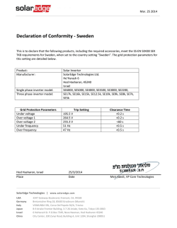
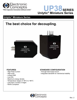
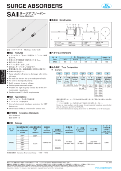
Isolation Amplifier with Short Circuit and Overload Detection HCPL-788J Features • • • • • • Output Voltage Directly Compatible with A/D Converters (0 V to VREF) • Fast (3 µs) Short Circuit Detection with Transient Fault Rejection • Absolute Value Signal Output for Overload Detection 1 µV/°C Offset Change vs. Temperature SO-16 Package -40°C to +85°C Operating Temperature Range 25 kV/µs Isolation Transient Immunity Regulatory Approvals (Pending): UL, CSA, VDE 0884 (891 Vpeak Working Voltage) Low Cost Three Phase Current Sensing with Short Circuit and Overload Detection ISOLATION BOUNDARY RSENSE1 1 VIN+ 2 VIN- SHORT CIRCUIT FAULT 15 3 FAULT 14 4 ABSVAL VOUT 13 5 6 VREF 12 MICRO CONTROLLER 11 10 7 8 +5 V 16 HCPL-788J 9 ISOLATION BOUNDARY RSENSE2 M 1 VIN+ 2 VIN- A/D CONVERTER 16 15 3 FAULT 14 4 13 5 ABSVAL VOUT 6 VREF 12 10 8 9 HCPL-788J VREF 11 7 3 PHASE MOTOR ISOLATION BOUNDARY RSENSE3 1 VIN+ 2 VIN- 3 PHASE ABSOLUTE VALUE OUTPUT 16 15 3 FAULT 14 4 13 + 5 ABSVAL VOUT 12 – 6 VREF 7 8 11 + – 10 HCPL-788J OVERLOAD FAULT 9 VTH Agilent Technologies Isolation Amplifier with Short Circuit and Overload Detection makes motor phase current sensing compact, affordable and easy-to-implement while satisfying worldwide safety and regulatory requirements. CAUTION: It is advised that normal static precautions be taken in handling and assembly of this component to prevent damage and/or degradation which may be induced by ESD. 1 HCPL-788J Description (ABSVAL) are also provided. The wire OR-able overrange output (FAULT) is useful for quick detection of short circuit conditions on any of the motor phases. The wire-OR-able rectified output (ABSVAL), simplifies measurement of motor load since it performs polyphase rectification. Since the common-mode voltage swings several hundred volts in tens of nanoseconds in modern electronic motor drives, the HCPL-788J was designed to ignore very high common-mode transient slew rates (10 kV/µ s). The HCPL-788J isolation amplifier is designed for current sensing in electronic motor drives. In a typical implementation, motor currents flow through an external resistor and the resulting analog voltage drop is sensed by the HCPL-788J. A larger analog output voltage is created on the other side of the HCPL-788J’s optical isolation barrier. The output voltage is proportional to the motor current and can be connected directly to a single-supply A/D converter. A digital overrange output (FAULT) and an analog rectified output ISOLATION BOUNDARY INPUT CURRENT HCPL-788J 39 Ω + 1 RSHUNT 0.02 Ω VIN+ GND2 µC 16 0.1 µF .01 µF VDD2 15 CH FAULT 14 4 CL ABSVAL 13 5 VDD1 VOUT 12 A/D 6 VLED+ VREF 11 VREF 7 VDD1 VDD2 10 8 GND1 GND2 9 2 VIN- 3 4.7 kΩ TO OTHER PHASE OUTPUTS 0.1 µF ISOLATED +5 V 0.1 µF GND +5 V Figure 1. Current Sensing Circuit. Pin Descriptions Symbol VIN+ Description Symbol Positive input voltage (±200 mV recommended). VIN- Negative input voltage (normally connected to GND1). CH Internal Bias Node. Connections to or between CH and CL other than the required 0.1 µF capacitor shown, are not recommended. GND2 VDD2 FAULT Supply voltage input (4.5 V to 5.5 V). Short circuit fault output. FAULT changes from a high to low output voltage within 6 µs after VIN exceeds the FAULT Detection Threshold. FAULT is an open drain output which allows outputs from all the HCPL-788Js in a circuit to be connected together (“wired-OR”) forming a single fault signal for interfacing directly to the micro-controller. ABSVAL Absolute value of VOUT output. ABSVAL is 0 V when VIN=0 and increases toward VREF as VIN approaches +256 mV or -256 mV. ABSVAL is “wired-OR” able and is used for detecting overloads. CL VDD1 Supply voltage input (4.5 V to 5.5 V). VLED+ LED anode. This pin must be left unconnected for guaranteed data sheet performance. (For optical coupling testing only.) VDD1 Supply voltage input (4.5 V to 5.5 V). GND1 Ground input. VOUT Voltage output. Swings from 0 to VREF. The nominal gain is VREF /504 mV. VREF Reference voltage input (4.0 V to VDD2). This voltage establishes the full scale output ranges and gains of VOUT and ABSVAL. VDD2 Supply voltage input (4.5 V to 5.5 V). GND2 2 Description Ground input. Ground input. HCPL-788J Ordering Information Specify Part Number followed by Option Number (if desired). Example HCPL-788J#XXX No Option = 16-Lead, Surface Mt. package, 45 per tube. 500 = Tape and Reel Packaging Option, 850 per reel. Option Data sheets available. Contact Agilent Technologies sales representative, authorized distributor, or visit our Web site at www.hp.com/go/isolator. 0.018 (0.457) Package Outline Drawings 16-Lead Surface Mount 0.050 (1.270) 16 15 14 13 12 11 10 9 TYPE NUMBER DATE CODE dimensions in inches (millimeters) A 788J HP YYWW Note: Initial and continued variation in the color of the HCPL-788J’s white mold compound is normal and does not affect device performance or reliability. 1 2 3 4 5 0.295 ± 0.010 (7.493 ± 0.254) 6 7 8 0.406 ± 0.10 0.01 (10.312 ± 0.254) 0.345 ± 0.010 (8.986 ± 0.254) 9° 0.138 ± 0.005 (3.505 ± 0.127) 0.018 (0.457) 0–8° 0.025 MIN. 0.408 ± 0.010 (10.160 ± 0.254) ALL LEADS TO BE COPLANAR ± 0.002 0.008 ± 0.003 (0.203 ± 0.076) STANDOFF Package Characteristics Parameter Symbol Min. Typ. Max. Input-Output Momentary Withstand Voltage VISO 3750 Resistance (Input-Output) RI-O >109 Ω VI-O = 500 VDC Capacitance (Input-Output) CI-O 1.3 pF f = 1 MHz Input IC Junction-to-Case Thermal Resistance θjci 120 °C/W TA = 85°C Output IC Junction-to-Case Thermal Resistance θjco 100 Vrms TEMPERATURE – °C Maximum Solder Reflow Temperature Profile 260 240 220 200 180 160 140 120 100 ∆T = 145°C, 1°C/SEC ∆T = 115°C, 0.3°C/SEC 80 60 40 20 0 ∆T = 100°C, 1.5°C/SEC 0 1 2 3 4 5 6 7 8 9 10 Units 11 12 TIME – MINUTES (NOTE: USE OF NON-CHLORINE ACTIVATED FLUXES IS RECOMMENDED.) 3 Test Conditions RH < 50%, t = 1 min., TA = 25°C Fig. Notes 1,2,3 3 HCPL-788J Regulatory Information The HCPL-788J is pending approval by the following organizations: VDE Approved under VDE0884/06.92 with V IORM = 891 Vpeak. CSA Approved under CSA Component Acceptance Notice #5, File CA 88324. UL Recognized under UL 1577, component recognition program, File E55361. VDE 0884 Insulation Characteristics* Description Symbol Installation classification per DIN VDE 0110/1.89, Table 1 for rated mains voltage ″ 300 Vrms or rated mains voltage ″ 300 Vrms for rated mains voltage ″ 600 Vrms Characteristic Unit I-IV I-III I-II Climatic Classification Pollution Degree (DIN VDE 0110/1.89) 55/85/21 2 Maximum Working Insulation Voltage VIORM 891 VPEAK Input to Output Test Voltage, Method b** VIORM x 1.875 = VPR, 100% Production Test with tm = 1 sec, Partial discharge < 5 pC VPR 1670 VPEAK Input to Output Test Voltage, Method a** VIORM x 1.5 = VPR, Type and Sample Test, tm = 60 sec, Partial discharge < 5 pC VPR 1336 VPEAK VIOTM 6000 VPEAK TS PS1, INPUT PS1, OUTPUT 175 400 600 ϒC mW mW RS >109 Highest Allowable Overvoltage (Transient Overvoltage tini = 10 sec) Safety-limiting values — maximum values allowed in the event of a failure, also see Figure 2. Case Temperature Input Power Output Power Insulation Resistance at TSI, VIO = 500 V * ** Isolation characteristics are guaranteed only within the safety maximum ratings which must be ensured by protective circuits within the application. Surface Mount Classification is class A in accordance with CECC00802. Refer to the optocoupler section of the isolation and Control Components Designer’s Catalog, under Product Safety Regulations section, (VDE-0884) for a detailed description of Method a and Method b partial discharge test profiles. 800 Ps – POWER – mW Psi – OUTPUT Psi – INPUT 600 400 200 0 0 25 50 75 100 125 150 175 200 TS – CASE TEMPERATURE – °C Figure 2. Dependence of SafetyLimiting Values on Temperature. 4 HCPL-788J Insulation and Safety Related Specifications Parameter Symbol Min. Max. L(101) 8.3 mm Measured from input terminals to output 8.3 mm terminals, shortest distance through air. Measured from input terminals to output terminals, shortest distance path along body. 0.5 mm >175 Volts Minimum External Air Gap (Clearance) Minimum External Tracking (Creepage) L(102) Minimum Internal Plastic Gap (Internal Clearance) Tracking Resistance (Comparative Tracking Index) CTI Isolation Group IIIa Conditions Through insulation distance conductor to conductor, usually the straight line distance thickness between the emitter and detector. DIN IEC 112/VDE 0303 Part 1 Material Group (DIN VDE 0110, 1/89, Table 1) Absolute Maximum Ratings Parameter Symbol Min. Max. Units Storage Temperature TS -55 125 °C Operating Temperature TA -40 100 Supply Voltages Steady-State Input Voltage 2 Second Transient Input Voltage Output Voltage VDD1, VDD2 0.0 5.5 VIN+, VIN- -2.0 -6.0 VDD1 + 0.5 VOUT -0.5 VDD2 + 0.5 ABSVAL -0.5 VDD2 + 0.5 Reference Input Voltage VREF 0 VDD2 + 0.5 V Reference Input Current Output Current IREF IVOUT 20 20 Absolute Value Current IABSVAL 20 FAULT Output Current IFAULT 20 Input IC Power Dissipation PI 200 Output IC Power Dissipation PO 200 Absolute Value Output Voltage Solder Reflow Temperature Profile V Note 4 5 mA mW See Package Outline Drawings section Recommended Operating Conditions Parameter Ambient Operating Temperature Supply Voltages Input Voltage (accurate and linear) Input Voltage (functional) Symbol Min. Max. Units TA VDD1, VDD2 VIN+, VIN- -40 85 °C 4.5 -200 5.5 200 V mV V VIN+, VIN- -2 2 Reference Input Voltage VREF 4.0 VDD2 FAULT Output Current IFAULT 4 5 mA Note HCPL-788J DC Electrical Specifications Unless otherwise noted, all typicals and figures are at the nominal operating conditions of VIN+ = 0, VIN- = 0 V, VREF = 4.0 V, VDD1 = VDD2 = 5 V and TA = 25°C; all Minimum/Maximum specifications are within the Recommended Operating Conditions. Parameter Input Offset Symbol Min. Typ. Max. Units Test Conditions VOS -3 0 3 mV VIN+ = 0 V 1 10 µV/°C Voltage Magnitude of Input |∆VOS/∆TA| Offset Change vs. Temperature VOUT Gain 6 7 VREF/504 mV VREF/504 mV + 5% V/V |VIN+|<200 mV 6,7, 50 300 ppm/°C |VIN+|<200 mV 8,9 8 NL200 0.06 0.4 Maximum Input Voltage Before VOUT Clipping |VIN+|MAX 256 FAULT Detection Threshold FAULT Low Output Voltage |VTHF| 10 9 11 10 VOUT 200 mV Nonlinearity VREF/504 mV - 5% Note |∆G/∆TA| Magnitude of VOUT Gain Change vs. Temperature G Fig. 3, 4, 5 230 % mV 256 280 VOLF 350 800 FAULT High Output Current IOHF 0.2 15 µA ABSVAL Output Error eABS 0.6 2 % of full scale output Input Supply IDD1 10.7 20 mA IDD2 10.4 20 IVREF 0.26 1 Input Current IIN+ -350 nA Input Resistance RIN 800 kΩ VOUT Output Resistance ROUT 0.2 Ω ABSVAL Output Resistance RABS 0.3 IOL = 4 mA VFAULT = VDD2 Current Output Supply Current Reference voltage Input Current Input DC Common- CMRRIN Mode Rejection Ratio 85 dB 6 VIN+ = 0 V 11 HCPL-788J AC Electrical Specifications Unless otherwise noted, all typicals and figures are at the nominal operating conditions of VIN+ = 0, VIN- = 0 V, VREF = 4.0 V, VDD1 = VDD2 = 5 V and TA = 25°C; all Minimum/Maximum specifications are within the Recommended Operating Conditions. Symbol Min. Typ. VOUT Bandwidth (-3dB) Parameter BW 20 30 Max. Units kHz VOUT Noise NOUT 2.2 4 mVrms VIN to VOUT Signal Delay (50 - 50%) tDSIG 9 20 µs VOUT Rise/Fall Time (10–90%) tRFSIG 10 25 ABSVAL Signal Delay tDABS 9 20 ABSVAL Rise/Fall Time (10–90%) tRFABS 10 25 FAULT Detection Delay tFHL 3 6 FAULT Release Delay tFLH 10 20 Transient Fault Rejection tREJECT 1 2 Common Mode Transient Immunity CMTI 10 25 kV/µs Common-Mode Rejection CMRR >140 dB Ratio at 60 Hz 7 Test Conditions Fig. Note VIN+ = 200 mVpk-pk sine wave. VIN+ = 0 V 12, 20 20 VIN+ = 50 mV to 200 mV step. 14, 20 13 VIN+ = 0 mV to ±500 mV step. VIN+ = ±500 mV to 0 mV step. 15, 20 16, 20 14 VIN+ = 0 mV to ±500 mV pulse. 17, 20 16 For VOUT, FAULT, and ABSVAL outputs. 12 15 17 18 HCPL-788J Notes: 1. In accordance with UL1577, each optocoupler is proof tested by applying an insulation test voltage ≥ 4200 Vrms for 1 second (leakage detection current limit, I I-O ≤ 5 µ A). This test is performed before the 100% production test for partial discharge (method b) shown in VDE 0884 Insulation Characteristic Table, if applicable. 2. The Input-Output Momentary Withstand Voltage is a dielectric voltage rating that should not be interpreted as an input-output continuous voltage rating. For the continuous voltage rating refer to your equipment level safety specification or VDE0884 insulation characteristics table. 3. Device considered a two terminal device: pins 1-8 shorted together and pins 9-16 shorted together. 4. V DD1 must be applied to both pins 5 and 7. VDD2 must be applied to both pins 10 and 15. 5. If VREF exceeds VDD2 (due to power-up sequence, for example), the current into pin 11 (IREF) should be limited to 20 mA or less. 6. Input Offset voltage is defined as the DC Input voltage required to obtain an output voltage (at pin 12) of VREF/2. 7. This is the Absolute Value of Input Offset Change vs. Temperature. 8. This is the Absolute Value of VOUT Gain Change vs. Temperature. 9. |VIN+| must exceed this amount in order for the FAULT output to be activated. 10. ABSVAL is derived from VOUT (which has the gain and offset tolerances stated earlier). ABSVAL is 0 V when VIN = 0 V and increases toward VREF as VIN approaches +256 mV or -256 mV. e ABS is the difference between the actual ABSVAL output and what ABSVAL should be, given the value of VOUT. eABS is expressed in terms of percent of full scale and is defined as |ABSVAL - 2 x | VOUT - VREF / 2|| x 100. VREF 11. CMRR IN is defined as the ratio of the gain for differential inputs applied between pins 1 and 2 to the gain for common mode inputs applied to both pins 1 and 2 with respect to pin 8. 12. The signal-to-noise ratio of the HCPL-788J can be improved with the addition of an external low pass filter to the output. See Frequently Asked Question #4.2 in the Applications Information Section at the end of this data sheet. 13. As measured from 50% of VIN to 50% of VOUT. 14. This is the amount of time from when the FAULT Detection Threshold (230 mV ≤ VTHF ≤ 280 mV) is exceeded to when the FAULT output goes low. 15. This is the amount of time for the FAULT Output to return to a high state once the FAULT Detection Threshold (230 mV ≤ V THF ≤ 280 mV) is no longer exceeded. 16. Input pulses shorter than the fault rejection pulse width (tREJECT), will not activate the FAULT (pin 14) output. See Frequently Asked Question #2.3 in the Applications Information Section at the end of this data sheet for additional detail on how to avoid false tripping of the FAULT output due to cable capacitance charging transients. 17. CMTI is also known as Common Mode Rejection or Isolation Mode Rejection. It is tested by applying an exponentially rising/falling voltage step on pin 8 (GND1) with respect to pin 9 (GND2). The rise time of the test waveform is set to approximately 50 ns. The amplitude of the step is adjusted until VOUT (pin 12) exhibits more than 100 mV deviation from the average output voltage for more than 1µs. The HCPL-788J will continue to function if more than 10 kV/µs common mode slopes are applied, as long as the break-down voltage limitations are observed. [The HCPL-788J still functions with common mode slopes above 10 kV/µ s, but output noise may increase to as much as 600 mV peak to peak.] 18. CMRR is defined as the ratio of differential signal gain (signal applied differentially between pins 1 and 2) to the common mode gain (input pins tied to pin 8 and the signal applied between the input and the output of the isolation amplifier) at 60 Hz, expressed in dB. 8 TYPICAL MAX 600.0 400.0 200.0 0 -200.0 -400.0 -600.0 -20 0 20 40 60 800 600 600 400 200 0 -200 -400 -600 -800 4.5 80 Figure 3. Input Offset Voltage Change vs. Temperature. 1.0 2.5 2.0 1.5 1.0 0 -300 -200 -100 0 100 200 300 0 -1.0 1.5 1.0 0.5 0 -0.5 -1.0 -1.5 5.5 OUTPUT SUPPLY VOLTAGE – VDD2 – V Figure 9. Gain Change vs. VDD2. FAULT OUTPUT VOLTAGE – FAULTBAR – V 2.0 4.75 5.0 5.25 5.5 1.0 0.5 0 -0.5 -1.0 -1.5 -20 0 20 40 60 -2.0 4.5 80 5.0 4.0 3.5 3.0 2.5 2.0 1.5 1.0 0.5 0 100 200 300 INPUT VOLTAGE – VIN – mV Figure 10. FAULT Output Voltage vs. VIN. 9 5.0 5.25 5.5 Figure 8. Gain Change vs. VDD1. 4.5 0 -300 -200 -100 4.75 INPUT SUPPLY VOLTAGE – VDD1 – V Figure 7. Gain Change vs. Temperature. 5.25 -600 TEMPERATURE – °C Figure 6. VOUT vs. VIN. 5.0 -400 1.5 -0.5 INPUT VOLTAGE – VIN – mV 4.75 -200 2.0 TYPICAL WORST CASE 0.5 -2.0 -40 0 Figure 5. Input Offset Voltage Change vs. VDD2. -1.5 0.5 200 OUTPUT SUPPLY VOLTAGE – VDD2 – V ∆GAIN CHANGE-% 1.5 3.0 400 -800 4.5 5.5 2.0 3.5 ∆GAIN CHANGE-% VOUT – OUTPUT VOLTAGE – V 5.25 Figure 4. Input Offset Voltage Change vs. VDD1. 4.0 ∆GAIN CHANGE-% 5.0 INPUT SUPPLY VOLTAGE – VDD1 – V TEMPERATURE – DEG C -2.0 4.5 4.75 ABSVAL – ABSOLUTE VALUE OUTPUT – V -800.0 -40 800 ∆VOS OFFSET CHANGE – µV 800.0 ∆VOS OFFSET CHANGE – µV INPUT OFFSET CHANGE - ∆VOS - uV HCPL-788J 4.0 3.5 3.0 2.5 2.0 1.5 1.0 0.5 0 -300 -200 -100 0 100 200 INPUT VOLTAGE – VIN – mV Figure 11. ABSVAL Output Voltage vs. VIN. 300 HCPL-788J 3.5 FAULT DETECTION DELAY – µs 35 34 BANDWIDTH – kHz 33 32 31 30 29 28 27 26 25 -40 -20 0 20 40 60 80 300 mV 0 mV VIN 300 mV/D -300 mV 5V 3.25 2.5 V 3.0 VOUT (PIN 12) 2.5 V/D 0V 5V 2.75 2.5 V ABSVAL (PIN 13) 2.5 V/D 0V 2.5 5V -40 TEMPERATURE – °C -20 0 20 40 60 80 TEMPERATURE – °C 2.5 V FAULT (PIN 14) 2.5 V/D 0V 5.00 µs/DIV Figure 12. Bandwidth vs. Temperature. 300 mV 0 mV Figure 13. FAULT Detection Delay vs. Temperature. 0 mV -300 mV 5V VOUT (PIN 12) 2.5 V/D 0V 5V 2.5 V ABSVAL (PIN 13) 2.5 V/D 2.5 V 0V 0V 5V 5V FAULT (PIN 14) 2.5 V/D 0V 2V VIN 300 mV/D VOUT (PIN 12) 2.5 V/D 2.5 V VOUT (PIN 12) 2.5 V/D 0V 5V ABSVAL (PIN 13) 2.5 V/D 2.5 V 0V ABSVAL (PIN 13) 2.5 V/D 2.5 V 0V 5.0 V 5V FAULT (PIN 14) 2.5 V/D 0V 2.5 V FAULT (PIN 14) 2.5 V/D 0V 5.00 µs/DIV Figure 18. Detection of 6 µs Fault 0 to 2 V to 0 Input, at VREF = 5 V. ABSVAL (PIN 13) 2.5 V/D 2.5 V 2.5 V FAULT (PIN 14) 2.5 V/D 0V 0 mV 2.5 V VOUT (PIN 12) 2.5 V/D 5V FAULT (PIN 14) 2.5 V/D Figure 16. FAULT Release, 300 to 0 mV Input, at VREF = 5 V. -300 mV 5V VIN 300 mV/D 0V VIN 2.0 V/D -2 V 5.0 V 2.5 V ABSVAL (PIN 13) 2.5 V/D 5.00 µs/DIV 300 mV 2.5 V 0V 5V 0V Figure 15. FAULT Detection, 0 to 300 mV Input, at VREF = 5 V. 0V 5.0 V VOUT (PIN 12) 2.5 V/D 2.5 V 5.00 µs/DIV 0 mV -300 mV 5V 0V 5V 2.5 V 0 mV VIN 300 mV/D -300 mV 5V 2.5 V 2.5 V 300 mV 300 mV VIN 300 mV/D Figure 14. Step Response, 0 to 200 mV Input, at VREF = 5 V. 100 µs/DIV Figure 19. Sine Response 400 mV pk to pk 4 kHz Input, at VREF = 5 V. 10 5.00 µs/DIV Figure 17. FAULT Rejecting a 1 µs, 0 to 2 V to 0 Input. Rejection is Independent of Amplitude. HCPL-788J 5V 4.7 kΩ 50 Ω VIN+ 14 1 10 Ω FAULT 13 0.01 µF ABSVAL 12 3 VOUT 11 VREF 0.1 µF 4 HCPL-788J 0.1 µF 6 5, 7 VDD1 0.1 µF 2, 8 10,15 9, 16 VDD2 0.1 µF Figure 20. AC Test Circuit. HCPL-788J 1 2 VIN+ VIN- FAULT DETECT Σ∆ MODULATOR DECODER 3 CH 4 CL VREF 11 VOUT 12 ABSVAL 13 FAULT 14 VDD2 15 VDD2 10 GND2 9 GND2 16 ENCODER D/A LPF 256 mV REFERENCE RECTIFIER 6 5 VLED+ VDD1 7 VDD1 8 GND1 Figure 21. Internal Block Diagram. 11 HCPL-788J Applications Information sistors. The FAULT output is wire OR-able so that a short circuit on any one motor phase can be detected using only one signal. One other output is provided — the rectified output (ABSVAL). This output is also wire OR-able. The motor phase having the highest instantaneous rectified output pulls the common output high. When three sinusoidal motor phases are combined, the rectified output (ABSVAL) is essentially a DC signal representing the rms motor current. This single DC signal and a threshold comparator can indicate motor overload conditions before damage to the motor or drive occur. Figure 22 shows the ABSVAL output when 3 HCPL788Js are used to monitor a sinusoidal 60 Hz current. Figures 23 and 24 show the ABSVAL output when only 2 or 1 of the 3 phases are monitored, respectively. The HCPL-788J’s other main function is to provide galvanic isolation between the analog input and the analog output. An internal voltage reference determines the full-scale analog input range of the modulator (approximately ±256 mV); an input range of ±200 mV is recommended to achieve optimal performance. 4.0 4.0 3.0 3.0 3.0 2.0 1.0 0 ABSVAL – V 4.0 ABSVAL – V ABSVAL – V Production Description Figure 21 shows the internal block diagram of the HCPL-788J. The analog input (VIN) is converted to a digital signal using a sigma-delta (∑-∆) analog to digital (A/D) converter. This A/D samples the input 6 million times per second and generates a high speed 1-bit output representing the input very accurately. This 1 bit data stream is transmitted via a light emitting diode (LED) over the optical barrier after encoding. The detector converts the optical signal back to a bit stream. This bit stream is decoded and drives a 1 bit digital to analog (D/A) converter. Finally a low pass filter and output buffer drive the output signal (V OUT) which linearly represents the analog input. The output signal full-scale range is determined by the external reference voltage (VREF). By sharing this reference voltage (which can be the supply voltage), the full-scale range of the HCPL-788J can precisely match the full-scale range of an external A/D converter. In addition, the HCPL-788J compares the analog input (VIN) to both the negative and positive full-scale values. If the input exceeds the full-scale range, the short-circuit fault output (FAULT) is activated quickly. This feature operates independently of the ∑∆ A/D converter in order to provide the high-speed response (typically 3 µs) needed to protect power tran- 2.0 1.0 1.0 0 0.01 0.02 0.03 0.04 TIME – SECONDS Figure 22. ABSVAL with 3 Phases, Wired-ORed Together. 0 2.0 0 0.01 0.02 0.03 0.04 TIME – SECONDS Figure 23. ABSVAL with 2 Phases, Wired-ORed Together. 12 0 0 0.01 0.02 0.03 0.04 TIME – SECONDS Figure 24. ABSVAL with 1 Phase. HCPL-788J R2 39 Ω + INPUT CURRENT R SHUNT 0.02 Ω R1 HCPL-788J .01 µF C3 0.1 µF ISOLATED +5 V C1 0.1 µF 1 VIN+ GND2 16 2 VIN- VDD2 15 3 CH FAULT 14 4 CL ABSVAL 13 5 VDD1 VOUT 12 A/D 6 VLED1+ VREF 11 VREF 7 VDD1 VDD2 10 8 GND1 GND2 9 C6 0.1 µF C2 R3 4.7 kΩ µC TO OTHER PHASE OUTPUTS C8 C4 C7 C5 GND +5 V C5 = C7 = C8 = 470 pF C4 = 0.1 µF Figure 25. Recommended Applications Circuit. + HV+ FLOATING POWER SUPPLY GATE DRIVE CIRCUIT – R4 R2 39 Ω D1 5.1 V C2 0.01 µF MOTOR + HCPL-788J C1 0.1 µF R1 + RSENSE HV- 5 VDD1 GND2 16 1 VIN+ VDD2 15 2 VIN- FAULT 14 8 GND1 ABSVAL 13 7 VDD1 VOUT 12 3 CH VREF 11 4 CL VDD2 10 6 VLED+ GND2 9 Figure 26. Recommended Supply and Sense Resistor Connections. Analog Interfacing Power Supplies and Bypassing The recommended supply connections are shown in Figure 26. A floating power supply (which in many applications could be the same supply that is used to drive the high-side power transistor) is regulated to 5 V using a simple zener diode (D1); the value of resistor R4 should be chosen to supply sufficient current from the existing floating supply. The voltage from the current sensing resistor (Rsense) is applied to the input of the HCPL-788J through an RC anti-aliasing filter (R2 and C2). Although the application circuit is relatively simple, a few recommendations should be followed to ensure optimal performance. The power supply for the HCPL-788J is most often obtained from the same supply used to power the power transistor gate drive circuit. If a dedicated supply is required, in many cases it is possible to add an additional winding on an existing transformer. Otherwise, some sort of simple isolated supply can be used, such as a line powered transformer or a highfrequency DC-DC converter. An inexpensive 78L05 three-terminal regulator can also be used to reduce the floating supply voltage to 5 V. To help attenuate high-frequency power supply noise or ripple, a resistor or inductor can be used in series with 13 HCPL-788J the input of the regulator to form a low-pass filter with the regulator’s input bypass capacitor. PC Board Layout The design of the printed circuit board (PCB) should follow good layout practices, such as keeping bypass capacitors close to the supply pins, keeping output signals away from input signals, the use of ground and power planes, etc. In addition, the layout of the PCB can also affect the isolation transient immunity (CMTI) of the HCPL-788J, due primarily to stray capacitive coupling between the input and the output circuits. To obtain optimal CMTI performance, the layout of the PC board should minimize any stray coupling by maintaining the maximum possible distance between the input and output sides of the circuit and ensuring that any ground or power plane on the PC board does not pass directly below or extend much wider than the body of the HCPL-788J. As shown in Figure 25, 0.1 µ F bypass capacitors (C1, C3, C4, and C6) should be located as close as possible to the pins of the HCPL-788J. The bypass capacitors are required because of the high-speed digital nature of the signals inside the HCPL-788J. A 0.01 µF bypass capacitor (C2) is also recommended at the input due to the switched-capacitor nature of the input circuit. The input bypass capacitor also forms part of the antialiasing filter, which is recommended to prevent highfrequency noise from aliasing down to lower frequencies and interfering with the input signal. The input filter also performs an important reliability function — it reduces transient spikes from ESD events flowing through the current sensing resistor. TOP LAYER BOTTOM LAYER Figure 27. Example Printed Circuit Board Layout. 14 HCPL-788J Current Sensing Resistors The current sensing resistor should have low resistance (to minimize power dissipation), low inductance (to minimize di/dt induced voltage spikes which could adversely affect operation), and reasonable tolerance (to maintain overall circuit accuracy). Choosing a particular value for the resistor is usually a compromise between minimizing power dissipation and maximizing accuracy. Smaller sense resistance decreases power dissipation, while larger sense resistance can improve circuit accuracy by utilizing the full input range of the HCPL-788J. If the power dissipation in the sense resistor is too high, the resistance can be decreased below the maximum value to decrease power dissipation. The minimum value of the sense resistor is limited by precision and accuracy requirements of the design. As the resistance value is reduced, the output voltage across the resistor is also reduced, which means that the offset and noise, which are fixed, become a larger percentage of the signal amplitude. The selected value of the sense resistor will fall somewhere between the minimum and maximum values, depending on the particular requirements of a specific design. The first step in selecting a sense resistor is determining how much current the resistor will be sensing. The graph in Figure 28 shows the rms current in each phase of a three-phase induction motor as a function of average motor output power (in horsepower, hp) and motor drive supply voltage. The maximum value of the sense resistor is determined by the current being measured and the maximum recommended input voltage of the isolation amplifier. The maximum sense resistance can be calculated by taking the maximum recommended input voltage and dividing by the peak current that the sense resistor should see during normal operation. For example, if a motor will have a maximum rms current of 10 A and can experience up to 50% overloads during normal operation, then the peak current is 21.1 A (=10 x 1.414 x 1.5). Assuming a maximum input voltage of 200 mV, the maximum value of sense resistance in this case would be about 10 mΩ. When sensing currents large enough to cause significant heating of the sense resistor, the temperature coefficient (tempco) of the resistor can introduce nonlinearity due to the signal dependent temperature rise of the resistor. The effect increases as the resistor-to-ambient thermal resistance increases. This effect can be minimized by reducing the thermal resistance of the current sensing resistor or by using a resistor with a lower tempco. Lowering the thermal resistance can be accomplished by repositioning the current sensing resistor on the PC board, by using larger PC board traces to carry away more heat, or by using a heat sink. For a two-terminal current sensing resistor, as the value of resistance decreases, the resistance of the leads become a significant percentage of the total resistance. This has two primary effects on resistor accuracy. First, the effective resistance of the sense resistor can become dependent on factors such as how long the leads are, how they are bent, how far they are inserted into the board, and how far solder wicks up the leads during assembly (these issues will be discussed in more detail shortly). Second, the leads are typically made from a material, such as copper, which has a much higher tempco than the material from which the resistive element itself is made, resulting in a higher tempco overall. MOTOR OUTPUT POWER – HORSEPOWER The maximum average power dissipation in the sense resistor can also be easily calculated by multiplying the sense resistance times the square of the maximum rms current, which is about 1 W in the previous example. 40 440 380 220 120 35 30 Both of these effects are eliminated when a fourterminal current sensing resistor is used. A fourterminal resistor has two additional terminals that are Kelvin-connected directly across the resistive element itself; these two terminals are used to monitor the voltage across the resistive element while the other two terminals are used to carry the load current. Because of the Kelvin connection, any voltage drops across the leads carrying the load current should have no impact on the measured voltage. 25 20 15 10 5 0 0 5 10 15 20 25 30 35 MOTOR PHASE CURRENT – A (rms) Figure 28. Motor Output Horsepower vs. Motor Phase Current and Supply Voltage. 15 HCPL-788J When laying out a PC board for the current sensing resistors, a couple of points should be kept in mind. The Kelvin connections to the resistor should be brought together under the body of the resistor and then run very close to each other to the input of the HCPL-788J; this minimizes the loop area of the connection and reduces the possibility of stray magnetic fields from interfering with the measured signal. If the sense resistor is not located on the same PC board as the HCPL-788J circuit, a tightly twisted pair of wires can accomplish the same thing. Also, multiple layers of the PC board can be used to increase current carrying capacity. Numerous platedthrough vias should surround each non-Kelvin terminal of the sense resistor to help distribute the current between the layers of the PC board. The PC board should use 2 or 4 oz. copper for the layers, resulting in a current carrying capacity in excess of 20 A. Making the current carrying traces on the PC board fairly large can also improve the sense resistor’s power dissipation capability by acting as a heat sink. Liberal use of vias where the load current enters and exits the PC board is also recommended. Sense Resistor Connections The recommended method for connecting the HCPL788J to the current sensing resistor is shown in Figure 26. VIN+ (pin 1 of the HCPL-788J) is connected to the positive terminal of the sense resistor, while VIN- (pin 2) is shorted to GND1 (pin 8), with the power-supply return path functioning as the sense line to the negative terminal of the current sense resistor. This allows a single pair of wires or PC board traces to connect the HCPL-788J circuit to the sense resistor. By referencing the input circuit to the negative side of the sense resistor, any load current induced noise transients on the resistor are seen as a common-mode signal and will not interfere with the current-sense signal. This is important because the large load currents flowing through the motor drive, along with the parasitic inductances inherent in the wiring of the circuit, can generate both noise spikes and offsets that are relatively large compared to the small voltages that are being measured across the current sensing resistor. If the same power supply is used both for the gate drive circuit and for the current sensing circuit, it is very important that the connection from GND1 of the HCPL788J to the sense resistor be the only return path for supply current to the gate drive power supply in order to eliminate potential ground loop problems. The only direct connection between the HCPL-788J circuit and the gate drive circuit should be the positive power supply line. Please refer to Agilent Technologies Applications Note 1078 for additional information on using Isolation Amplifiers. 16 HCPL-788J Frequently Asked Questions about the HCPL-788J 1.␣ The Basics 1.1: Why should I use the HCPL-788J for sensing current when Hall-effect sensors are available which don’t need an isolated supply voltage? Historically, motor control current sense designs have required trade-offs between signal accuracy, response time, and the use of discrete components to detect short circuit and overload conditions. The HCPL-788J greatly simplifies current-sense designs by providing an output voltage which can connect directly to an A/D converter as well as integrated short circuit and overload detection (eliminating the need for external circuitry). Available in an auto-insertable, SO-16 package, the HCPL-788J is smaller than and has better linearity, offset vs. temperature and Common Mode Rejection (CMR) performance than most Hall-effect sensors. 1.2: What is the purpose of the VREF input? The VREF input establishes the full scale output range. VREF can be connected to the supply voltage (VDD2) or a voltage between 4 V and VDD2. The nominal gain of the HCPL-788J is the output full scale range divided by 504 mV. 1.3: What is the purpose of the rectified (ABSVAL) output on pin 13? When 3 phases are wire-ORed together, the 3 phase AC currents are combined to form a DC voltage with very little ripple on it. This can be simply filtered and used to monitor the motor load. Moderate overload currents which don’t trip the FAULT output can thus be detected easily. 2.␣ Sense Resistor and Input Filter 2.1: Where do I get 10 mΩ resistors? I have never seen one that low. Although less common than values above 10 Ω, there are quite a few manufacturers of resistors suitable for measuring currents up to 50 A when combined with the HCPL-788J. Example product information may be found at Dale’s web site (http:// www.vishay.com/vishay/dale) and Isotek’s web site (http://www.isotekcorp.com). 2.2: Should I connect both inputs across the sense resistor instead of grounding VINdirectly to pin 8? This is not necessary, but it will work. If you do, be sure to use an RC filter on both pin 1 (VIN+) and pin 2 (VIN-) to limit the input voltage at both pads. 2.3: How can I avoid false tripping of the fault output due to cable capacitance charging transients? In PWM motor drives there are brief spikes of current flowing in the wires leading to the motor each time a phase voltage is switched between states. The amplitude and duration of these current spikes is deter-mined by the slew rate of the power transistors and the wiring impedances. To avoid false tripping of the FAULT output (pin 14) the HCPL-788J includes a blanking filter. This filter ignores over-range input conditions shorter than 1 µ s. For very long motor wires, it may be necessary to increase the time constant of the input RC anti-aliasing filter to keep the peak value of the HCPL-788J inputs below ±230 For example, a 39 Ω, 0.047 µ F RC filter on pin 1 will ensure that 2 µs wide 500 mV pulses across the sense resistor do not trip the FAULT output. 17 HCPL-788J 2.4: Do I really need an RC filter on the input? What is it for? Are other values of R and C okay? This filter prevents damage from input spikes which may go beyond the absolute maximum ratings of the HCPL-788J inputs during ESD and other transient events. The filter also prevents aliasing of high frequency (above 3 MHz) noise at the sampled input. Other RC values are certainly OK, but should be chosen to prevent the input voltage (pin 1) from exceeding ±5 V for any conceivable current waveform in the sense resistor. Remember to account for in ductance of the sense resistor since it is possible to momentarily have tens of volts across even a 1 mΩ resistor if di/dt is quite large. 2.5: How do I ensure that the HCPL-788J is not destroyed as a result of short circuit conditions which cause voltage drops across the sense resistor that exceed the ratings of the HCPL-788J’s inputs? Select the sense resistor so that it will have less than 5 V drop when short circuits occur. The ony other requirement is to shut down the drive before the sense resistor is damaged or its solder joints melt. This ensures that the input of the HCPL-788J can not be damaged by sense resistors going open-circuit. 3.␣ Isolation and Insulation 3.1: How many volts will the HCPL-788J withstand? The momentary (1 minute) withstand voltage is 3500 V rms per UL1577 and CSA Component Acceptance Notice #5. 3.2: What happens if I don’t use the 470 pF output capacitors Agilent recommends? These capacitors are to reduce the narrow output spikes caused by high common mode slew rates. If your application does not have rapid common mode voltage changes, these capacitors are not needed. 4.␣ Accuracy For zero input, the output should ideally be 1/ 2 of VREF. The nominal slope of the input/output relationship is VREF divided by 0.504 V. Offset errors change only the DC input voltage needed to make the output equal to 1/2 of VREF. Gain errors change only the slope of the input/output relationship. For example, if VREF is 4.0 V, the gain should be 7.937 V/V. For zero input, the output should be 2.000 V. Input offset voltage of ±3 mV means the output voltage will be 2.000 V ±0.003*7.937 or 2.000 ±23.8 mV when the input is zero. Gain tolerance of ±5% means that the slope will be 7.937 ±0.397. Over the full range of ±3 mV input offset error and ±5% gain error, the output voltage will be 2.000 ±25.0 mV when the input is zero. 4.1: What is the meaning of the offset errors and gain errors in terms of the output? 18 HCPL-788J 4.2: Can the signal to noise ratio be improved? Yes. Some noise energy exists beyond the 30 kHz bandwidth of the HCPL-788J. An external RC low pass filter can be used to improve the signal to noise ratio. For example, a 680 Ω, 4700 pF RC filter will cut the rms output noise roughly by a factor of 2. This filter reduces the -3dB signal bandwidth only by about 10%. In applications needing only a few kHz bandwidth even better noise performance can be obtained. The noise spectral density is roughly 400 nV/√ Hz below 15 kHz (input referred). As an example, a 2 kHz (680 Ω, 0.1 µ F) RC low pass filter reduces output noise to a typical value of 0.08 mVrms. 4.3: I need 1% tolerance on gain. Does Agilent sell a more precise version? At present HP does not have a standard product with tighter gain tolerance. A 100 Ω variable resistor divider can be used to adjust the input voltage at pin 1, if needed. 4.4: The output doesn’t go all the way to VREF when the input is above full scale. Why not? Op-amps are used to drive VOUT (pin 12) and ABSVAL (pin 13). These op-amps can swing nearly from rail to rail when there is no load current. The internal V DD2 is about 100 mV below the external V DD2. In addition, the pullup and pulldown output transistors are not identical in capability. The net result is that the output can typically swing to within 20 mV of GND2 and to within 150 mV of VDD2. When VREF is tied to VDD2, the output can not reach VREF exactly. This limitation has no effect on gain — only on maximum output voltage. The output remains linear and accurate for all inputs between -200 mV and +200 mV. For the maximum possible swing range, separate V REF and V DD2 voltages can be used. Since 5.0 V is normally recommended for VDD2, use of 4.5 V or 4.096 V references for VREF allow the outputs to swing all the way up to VREF (and down to typically 20 mV). 4.5: Does the gain change if the internal LED light output degrades with time? No. The LED is used only to transmit a digital pattern. Gain is determined by a bandgap voltage reference and the user-provided VREF. Agilent has accounted for LED degradation in the design of the product to ensure long life. 4.6: Why is gain defined as VREF/504 mV, not VREF/512 mV as expected, based on Figure 24? Ideally gain would be VREF/512 mV, however, due to internal settling characteristics, the average effective value of the internal 256 mV reference is 252 mV. 19 HCPL-788J 5.␣ Power Supplies and Start-Up 5.1: What are the output voltages before the input side power supply is turned on? VOUT (pin 12) is close to zero volts, ABSVAL (pin 13) is close to V REF and FAULT (pin 14) is in the high (inactive) state when power to the input side is off. In fact, a self test can be performed using this information. In a motor drive, it is possible to turn off all the power transistors and thus cause all the sense resistor voltages to be zero. In this case, finding V OUT less than 1/4 of V REF, ABSVAL more than 3/4 of VREF and FAULT in the high state indicates that power to the input side is not on. 5.2: How long does the HCPL-788J take to begin working properly after power-up? About 50 µs after a VDD2 power-up and 100 µs after a VDD1 power-up. 6.␣ Miscellaneous 6.1: How does the HCPL-788J measure negative signals with only a +5 V supply? The inputs have a series resistor for protection against large negative inputs. Normal signals are no more than 200 mV in amplitude. Such signals do not forward bias any junctions sufficiently to interfere with accurate operation of the switched capacitor input circuit. 6.2: What load capacitance can the HCPL-788J drive? Typically, noticeable ringing and overshoot begins for CLOAD above 0.02 µF. Agilent recommends keeping the load capacitance under 5000 pF (at pin 12). ABSVAL (pin 13) typically exhibits no instability at any load capacitance, but speed of response gradually slows above 470 pF load. 6.3: Can I use the HCPL-788J with a bipolar input A/D converter? Yes, with a compromise on offset accuracy. One way to do this is by connecting +2.5 V to pins 10, 11, and 15 and connecting -2.5 V to pins 9 and 16 with 0.1 µ F bypass capacitors from +2.5 V to -2.5 V and from -2.5 V to ground. Note that FAULT cannot swing above 2.5 V in this case, so a level shifter may be needed. Alternately, a single 5 V supply could be power the HCPL-788J which could drive an op amp configured to subtract 1/2 of VREF from VOUT. 20 フォトカプラ製品取扱い注意事項 洗浄について 環境規制について ・塩素系フラックス及び塩素系の洗浄剤のご使 フォトカプラを始め当社半導体部品には、オ 用は避けてください。 ゾン層破壊規制物質、並びに特定臭素系難燃材 ・一部の洗浄剤には高温下において塩素原子等 料(PBBOS、PBBS)は使用されていません。 が分離するものがありますので、洗浄剤の管 理についても十分注意を払う必要があります。 ・超音波洗浄につきましては、その条件等に 難燃性グレードについて 全ての当社フォトカプラは難燃性グレード よっては、ワイヤーボンディングへの影響を “UL94V-0”です。 始め、フォトカプラに悪影響を及ぼす可能性 が考えられますので、必ず十分に安全性をご 確認の上、実施されるようお願いします。 21 当社半導体部品のご使用にあたって 仕様及び仕様書に関して ・本仕様は製品改善および技術改良等により予告なく変更する場合があります。ご使用の際には最 新の仕様を問い合わせの上、用途のご確認をお願いいたします。 ・本仕様記載内容を無断で転載または複写することは禁じられております。 ・本仕様内でご紹介している応用例(アプリケーション)は当社製品がご使用できる代表的なもの です。 ご使用において第三者の知的財産権などの保証または実施権の許諾に対して問題が発生し た場合、当社はその責任を負いかねます。 ・仕様書はメーカとユーザ間で交わされる製品に関する使用条件や誤使用防止事項を言及するもの です。仕様書の条件外で保存、使用された場合に動作不良、機械不良が発生しても当社は責任を 負いかねます。 ・仕様書の製品が製造上および政策上の理由で満足できない場合には変更の権利を当社が有し、そ の交渉は当社の要求によりすみやかに行われることとさせて頂きます。 なお、基本的に変更は3ヶ 月前、廃止は 1 年前にご連絡致しますが、例外もございますので予めご了承ください。 ご使用用途に関して ・当社の製品は、一般的な電子機器(コンピュータ、OA 機器、通信機器、AV 機器、家電製品、ア ミューズメント機器、計測機器、一般産業機器など)の一部に組み込まれて使用されるものです。 極めて高い信頼性が要求される用途(輸送機器、航空・宇宙機器、海底中継器、原子力制御シス テム、生命維持のための医療機器など、財産・環境もしくは生命に悪影響を及ぼす可能性を持つ 用途)を意図し設計も、製造もされているものではありません。それゆえ、本製品の安全性、品 質および性能に関しては、仕様書(又は、カタログ)に記載してあること以外は明示的にも黙示 的にも一切の保証をするものではありません。 回路設計上のお願い ・当社は品質、信頼性の向上に努力しておりますが、一般的に半導体製品の誤動作や、故障の発生 は避けられません。本製品の使用に付随し、或いはこれに関連する誤動作、故障、寿命により、 他人の生命又は財産に被害や悪影響を及ぼし、或いは本製品を取り付けまたは使用した設備、施 設または機械器具に故障が生じ一般公衆に被害を起こしても、当社はその内容、程度を問わず、 一切の責任を負いかねます。 お客様の責任において、装置の安全性設計をお願いいたします。 22
© Copyright 2026 Paperzz