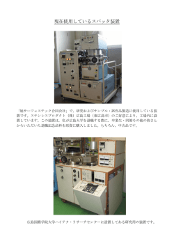
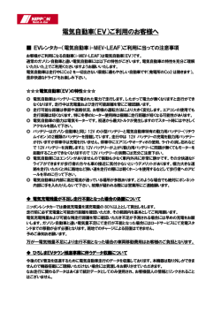
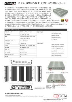
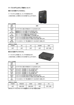
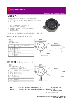
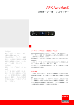
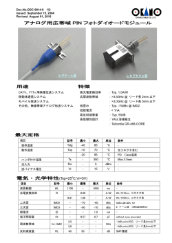
Precaution Notice
Only a technician, authorized by ENERMAX, is allowed to perform maintenance service!
Warranty is subject to void under unauthorized attempt to open the power case or
modification of any kinds, even attempted only, of the power supply or its components!
ENERMAX will not be responsible for damages caused by following situations:
Opening of the PSU case and/or modification of any component or cable without
ENERMAX’ written authorization.
Ignoring connector’s wrong insertion prevention design by attaching a connector to a
device in wrong orientation.
Connecting too many devices to one cable unit by using additional adaptor (Y cables).
Usage of non-genuine ENERMAX modular cables.
Damage caused by natural phenomena or uncontrollable forces, such as lightning,
flooding, fire, earthquake, etc.
This ENERMAX Technology Corporation product is warranted to be free from defects in
material and workmanship for a period of three (3) years from the date of purchase.
ENERMAX Technology Corporation agrees to repair or replace the product, at its own option
and at no charge, if, during the warranty period, it is returned to nearest ENERMAX
Technology Corporation subsidiary/agent with all shipping charges prepaid and bearing a
return merchandize authorization (RMA) number, and if inspection reveals that the product is
defective. Charges for removing or installing the product are excluded under the terms of this
warranty agreement. This warranty shall not apply to any product, which has been subject to
connection to a faulty power source, alteration, negligence, or accident, or to any product,
which has been installed other than in accordance with these instructions. In no event shall
ENERMAX Technology Corporation, or its subsidiaries, or agents be liable for damages for a
breach of warranty in an amount exceeding the purchase price of this product!
If you are uncertain whether or not your ENERMAX PSU is defective, please contact your
dealer/reseller for support!
Web Site: http://www.enermax.com
E-mail: [email protected]
ENERMAX Technology Corporation, 15F-2, No. 888, Jing-Guo Road, Taoyuan City (330), Taiwan (R.O.C.), Tel.
+886-3-316-1675, Fax. +886-3-346-6640
©2008 ENERMAX Technology Corporation. All rights reserved. Specifications are subject to change without prior notice.
Actual product and accessories may differ from illustrations. Omissions and printing errors excepted. Content of delivery might
differ in different countries or areas. Some trademarks may be claimed as the property of others. Reproduction in any manner
without the written permission of ENERMAX is strictly forbidden.
ENERMAX REVOLUTION 85+ Series Power Supply Specification
ERV850EWT
AC Input Voltage
AC Input Current
ERV950EWT
ERV1050EWT
115- 240VAC, 50-60Hz
(Maximum range: 100-264VAC, 47-63Hz)
9 – 4.5A
10 – 5A
11 – 5.5A
DC Output
Rated
3.3V
5V
12V1
12V2
12V3
12V4
12V5
12V6
-12V
5Vsb
Total Power
Peak Power
Over Current
Protection
(DC)
Under Voltage /
Over Voltage
Protection
(AC)
Under Voltage
Protection
Over Power
Protection
Over
Temperature
Protection
Short Circuit
Protection
Surge & Inrush
Protection
Temperature
Humidity
Cooling
MTBF
Dimension
Weight
Safety
EMC
Combined
0-25A
160W
0-25A
0-30A
0-30A
0-30A
840W
(70A)
0-30A
0-30A
0-30A
0-0.6A
7.2W
0-5A
25W
850W
1020W
DC Rail
3.3V
5V
12V1/2/3/4/5/6
DC Rail
3.3V
5V
12V1/2/3/4/5/6
-12V
Rated
Combined
0-25A
170W
0-25A
0-30A
0-30A
0-30A
948W
(79A)
0-30A
0-30A
0-30A
0-0.6A
7.2W
0-5A
25W
950W
1140W
Protection Circuit
Rated
Combined
0-25A
170W
0-25A
0-30A
0-30A
0-30A 1044W
(87A)
0-30A
0-30A
0-30A
0-0.6A
7.2W
0-5A
25W
1050W
1260W
ERV1250EGT
220-240VAC,
50-60Hz
7.5 – 6A
Rated
Combined
0-25A
170W
0-25A
0-30A
0-30A
0-30A
1248W
(104A)
0-30A
0-30A
0-30A
0-0.6A
7.2W
0-5A
25W
1250W
1500W
OCP trigger range
30 – 45A
30 – 45A
34 – 45A
UVP trigger range
OVP trigger range
2.0 – 2.4V
3.9 – 4.5V
3.3 – 3.7V
5.7 – 6.5V
8.5 – 9.5V
13.3 – 14.5V
-8.5 – -9.5V
-13.3 – -14.5V
Activated when AC input voltage < 70VAC.
Activated when output power > 110 ~160% of rated max load.
Activated when PSU heat sink > 90 ~ 110oC / 194 ~ 230oF.
Activated when any DC rails short-circuited.
Sustain 2KV surge stroke.
Sustain up to 70A inrush current @ 240VAC at cold start.
ENVIRONMENT
Operation ambient: 0~50oC/32~122oF (for full rated output)
Storage ambient: -40~70 oC/-40~158 oF
Operation: to 85% relative humidity, non-condensing at 25 oC/77 oF
Storage: to 95% relative humidity, non-condensing at 50 oC/122 oF
OTHERS
One 13.5cm two-ball bearing fan, speed auto controlled.
> 100,000 hours at 70% of full rated load, 230VAC/50Hz, 25 oC
(MIL-HDBK-217F standard)
150 (w) x 86 (h) x 190 (d) mm
2.95kg (without modular cables) ±50g
UL/cUL(Level 6), TUV, CCC, GOST, CB, BSMI(850W only)
CE, FCC, MIC
1
User’s Manual
Dear customer,
Thank you for choosing this ENERMAX REVOLUTION 85+ power supply unit (PSU)! Please read
this manual carefully and follow its instructions before installing the PSU.
We would like to draw your attention that a computer required very specific conditions to work best
for you without failing. To avoid failures and to increase lifetime of the system, we suggest that:
Your system is NOT located near a radiator or any other heat producing device
Your system is NOT located near a magnetic device
Your system is NOT located in a moist and/or dusty and/or vibrating environment
Your system is NOT exposed to direct sunshine
Your system is sufficiently cooled by additional fans
If you use AC extension cables, please make sure it can support all connected appliances’
potential peak power draw. Or redistribute other high power consumption equipment, such as
laser printers or monitors to other AC wall outlets. Exceeding the extension cable’s loading
capacity could trigger its circuit breaker and cut off the power.
If you want to add the UPS (Uninterruptible Power Supply) for your system, please choose
adequate Watts/VA capacity UPS. Ex.
PSU Model
Suggested minimum UPS output power capacity
(Based on efficiency & PFC at respective load)
ERV850EWT
1000W / 1400VA
ERV950EWT
1100W / 1600VA
ERV1050EWT
1200W / 1700VA
ERV1250EGT
1500W / 2100VA
* If you intend to add other appliance powered by the same UPS, such as monitor or printer,
please use higher capacity UPS according to all connected devices’ rated power draw.
* Please do not mistake VA capacity as Watts, or use insufficient power UPS. This would result
in less UPS battery runtime or the inability to power the system in battery mode.
COMPATIBILITY
ENERMAX REVOLUTION 85+ series is compliant with:
SSI PSDG 2008/2009 Power Supply Design Guide specification and downward compatible
with SSI PSDG 2008 1.0, EPS12V V2.92, 2.91 and 2.8
This PSU does not support MB with ISA expansion slot, which might need -5V power. -5V has
been cancelled from Intel ATX12V v1.3 specification onwards.
2
NAME OF PARTS
1Output cable: Please check “Cables &
Connectors” section.
2 13.5cm fan.# 1
3 Honeycomb air vent. # 1
4 PowerGuard LED
5 AC Inlet # 2
6 ON/OFF switch: (I=ON, O=OFF). # 2
#1 To ensure best system cooling, do not block PSU fan’s air in-take and air vent area.
This PSU offers a special HeatGuard function. When the system is turned off, or goes into ACPI
S3/S4 sleep mode, the PSU fan will keep dissipating the remaining heat for 30 ~ 60 seconds and
prolonging system lifetime.
#2 When assembling or maintaining the system, please remove AC cord from AC inlet, or turn
ON/OFF switch into “OFF” position, and wait PowerGuard LED light off. Then you can safely
service the system.
CABLES & CONNECTORS
All connectors are designed to prevent insertion in wrong orientation. If you cannot easily insert a
connector, please check if you are inserting the connector in the right orientation. Do not try by force
to insert it nor modify the connectors. This might damage power supply and system components, and
warranty shall be void.
Following graphic illustrates the modular sockets layout and its DC rail distribution.
5P BLACK sockets
The black sockets provide 3.3V/5V/12V for
modular cable to power drives or other
peripheral.
12P RED sockets
The red sockets provide 12V for modular cable
to power graphics card, CPU or RAM.
3
CONNECTOR TYPES
24P Mainboard
Native cable, 12V rail supplied by 12V1
For new generations of ATX/EEB/CEB server/workstation MB.
8P CPU +12V
Native cable, 12V rail supplied by 12V1 & V2
Supports multi-CPU server/workstation systems and some single socket systems.
4+4P (8P) CPU +12V, in combined mode
Native cable, 12V rail supplied by 12V1 & V2
8-pin configuration supports multi-CPU server/workstation systems and some
single extreme CPU systems.
4+4P (8P) CPU +12V, in split mode
Native cable, 12V rail supplied 12V1 & V2
4-pin configuration supports certain single CPU systems. Some multi-CPU
workstation/server system might also need this extra 4-pin 12V connector.
Please use the connector with “12V” marking.
6+2P (8P) PCI Express, in combined mode
Native cable, 12V rail supplied by 12V3
8-pin configuration supports latest extreme graphic cards, which require 8-pin
PCI-E connector.
6+2P (8P) PCI Express, in split mode / 6P PCI Express
Native cable, 12V rail supplied by 12V3
6-pin configuration supports most performance PCI-E graphic cards, which require
6-pin PCI-E connector.
SATA # 1
For SATA/SAS drives.
4P Molex # 2
For IDE/SCSI/SAS drives or some AGP graphic card with traditional 4P power in
socket.
FDD
For floppy drive or certain add-on card.
FM (FAN RPM MONITOR) # 3
For 13.5cm fan RPM detection.
Fan speed for 850 / 950 / 1050W models: 700-1500RPM (±10%).
Fan speed for 1250W model: 800-1800RPM (±10%).
#1 Some SATA drives might accept SATA or 4P Molex power. Normally, use either one of power
connector to power the driver, BUT NOT BOTH! Please check the drive’s manual for details.
#2 Some MB might require this connector to share the +12V current from 24-pin Mainboard
connector to PCI-E slot. If your MB already supports 24-pin Mainboard connector, you may not
need to add the 4P Molex connector on it. Please check the MB’s manual for details.
#3 Most MB offer 2 ~ 4 3-pin system/PSU fan power sockets, but only one or two socket(s) might
support the fan RPM signal. If you connect the PSU FM connector on the MB, but BIOS or
system monitor software cannot read the PSU fan RPM, please relocate the PSU FM connector to
another socket.
4
MODULAR CABLES SUPPLIED
Use ONLY genuine ENERMAX modular cables coming with ENERMAX PSU. Third party cables
might not be compatible and might cause damage to your PSU and/or system, and use of third party
cable shall void PSU warranty.
EMC012: 3 x 4P Molex (IDE/SCSI) drives
Modular cable for IDE/SCSI/SAS drives and other peripherals.
EMC013: 3 x 4P Molex (IDE/SCSI) drives & 1 X FDD connector
Modular cable for IDE/SCSI/SAS drives and peripheral, plus 1 FDD
power connector.
EMC014: 2 x 6+2P (8P) PCI-E 2.0
Modular cable for 1 or 2 performance PCI Express graphic cards,
which needs 6P or 8P PCI-E connector.
EMC017: 4 x SATA drives
Modular cable for SATA/SAS drives like ODD and HDD.
EMC018: 8P & 4P +12V CPU/RAM power (optional)
Modular cable to support special heavy-duty workstation/server with
more than 4 CPUs and 16 RAMs.
Supplied modular cables might differ by models and in different region.
We offer more optional cables. Please visit our website for more information:
www.enermax.com
Special note for System Integrators: If your system requires special modular cable configuration or
design, please contact an ENERMAX sales representative.
ATTACHING / DETACHING THE MODULAR CABLES
Attaching the modular cable to PSU
5-pin / 12-pin connector on modular cable and PSU’s modular socket has an
arrow mark. To make correct connection is easy:
1. Black connector to black socket, and red to red.
2. Arrow mark to arrow mark.
3. Then you can easily plug in the connector.
Detaching the modular cable from PSU
5-pin / 12-pin connector on modular cable has two hooks to lock with the
PSU’s modular sockets. When unplug the modular cable from PSU, please
press two hooks together and gently pull out the cable.
5
BOOTING YOUR SYSTEM
Before booting your system, please check that:
1. Main power connector (24P) is properly connected.
2. CPU +12V power connector (4 or 8-pin configuration), and/or a 4P Molex connector (if required
by MB) is properly connected.
3. All other needed connectors are properly connected.
4. AC cord is properly connected to wall outlet and PSU AC inlet.
5. Close your system chassis.
6. Turn on the PSU by switching the ON/OFF switch to “ON”, and your system is ready.
PROTECTION, SAFETY & SECURITY
This PSU features PowerGuard & SafeGuard function to monitor the PSU itself. With tri-color LED,
PowerGuard tells you the current PSU status. In case of abnormal situations, the power supply will
automatically turn off to avoid potential danger to itself and other system components.
PowerGuard indication
LED
ON/OFF
switch
OFF
OFF
OFF
ON
Orange
ON
PSU normal and system in standby/ sleep mode
Green
ON
PSU normal and system in operation
Information & what to do
* No AC input
- Turn the I/O switch to ON position.
* No AC input or PSU malfunction
- Check if AC cable is firmly plugged into wall outlet and AC inlet. If LED
still does not turn to orange light, then
- Contact ENERMAX service center.
* System abnormal, protection circuit activated.
If you push the system power button, and PSU refuse to turn on, the LED
turn from orange to red light:
- Short-Circuit protection activated.
- Completely check if all connectors are correctly inserted, and clean the
chassis to prevent undesired objects, which might short circuit any
device/terminal.
Red
ON
If during system operation, the PSU suddenly shut down
- Touch the PSU housing and check if it is hot. If yes, wait till it cool
down and restart the system to see if all system fans and PSU fan are
running. Add or replace the system fan if required.
- If same situation repeat, recheck if all connectors are well connected to
system, or redistribute certain drives/PCI-E power to different 12V rail
connector.
If you have any question or need support, please contact your reseller or nearest ENERMAX
subsidiary/agent or ENERMAX headquarter service center.
©2008 ENERMAX Technology Corporation. All rights reserved. Specifications are subject to change without prior notice.
Actual product and accessories may differ from illustrations. Omissions and printing errors excepted. Content of delivery might
differ in different countries or areas. Some trademarks may be claimed as the property of others. Reproduction in any manner
without the written permission of ENERMAX is strictly forbidden.
6
取扱説明書
ご挨拶
この度は ENERMAX 電源ユニットをお買い上げいただき、誠にありがとうございます。電
源ユニットを設置する前に、本マニュアルをよくお読みの上、正しくお使いください。
コンピュータは非常に壊れやすいシステムで、故障なく最適な動作を続けるには特定の条件
が必要になります。コンピュータの故障を避け、寿命を延ばすために、次の推奨事項に留意
してください。
コンピュータをラジエーターやその他の熱を発生する装置の近くに置かない。
コンピュータを磁気が発生する装置の近くに置かない。
コンピュータを湿気や埃、振動のある環境に置かない。
コンピュータを直射日光にさらさない。
PC ファンを追加してコンピュータを十分に冷却する。
複数の AC 延長ケーブルを使って、電源を取る場合は、同じ延長ケーブル内でレーザー
プリンタ、ラジエーター等、他の高電力消費装置を使用したり、延長ケーブルの安全電
流負荷基準を超えることのないようにしてください。
追加 UPS(無停止電源装置)を経由して電源を取る場合、接続デバイスの電力供給のた
め、十分なワット数とVA出力の UPS を選んでください。
型番
最高電力推測(W/VA)
ERV850EWT
1000W / 1400VA
ERV950EWT
1100W / 1600VA
ERV1050EWT
1200W / 1700VA
ERV1250EGT
1500W / 2100VA
* 同じ UPS からモニターやプリンターなどの高電力消費装置を接続する場合、UPS の
容量は更に大きなものを使用してください。電力低下の原因となります。
* VA とワット数を間違えないよう、また、不十分な容量の UPS を使用されないようご注
意ください。UPS バッテリーモード時にシステムが動作しない原因となります。
互換性
ENERMAX REVOLUTION 85+ シリーズは以下に準拠しています
SSI PSDG 2008・2009 パワーサプライデザインガイド及び、SSI PSDG 2008 1.0、及
び EPS12V V2.92・2.91・2.8 の下位互換。
お使いの MB に ISA バスがある場合、本電源ユニットには一部の ISA デバイスをサポー
トするための -5v レールがないため、
バスを完全にサポートできない可能性があります。
このレールは ATX12V v1.3 より廃止されました。
7
部品名
①出力ケーブル:
「ケーブルとコネクタ」の項を
参照してください
②13.5cm ファン# 1
③ハニカム構造# 1
④パワーガード LED
⑤AC インレット# 2
⑥I/O スイッチ*:電源 I/O(オン/オフ)スイッチ
(I=ON, O=OFF) # 2
#1 効率よく電源ユニットを冷却させるため、ファン部分や排出口が遮蔽物などにより遮られ
ることの無いよう設置してください。
本電源ユニットは独自の HeatGuard(冷却システム)を搭載しております。システムをシ
ャットダウンした後や、ACPI S3 /S4 のスリープモードに移行した後、システムの余熱を
取り除きハードの寿命を延ばす為、30~60 秒の間電源ユニットのファンが回転を続けます。
#2 ハードの取り外しやメンテナンスを行う際、電源ユニットの I/O スイッチを OFF にし、
LED ランプが消えたのを確認した後、AC コードプラグを抜いてください。
ケーブルとコネクタ
コネクタ誤挿入防止設計です。そして、簡単にデバイスに接続できるように設計されます。
もし、簡単に挿入することができないなら、コネクタが正しい方向に挿入されているかどう
かをお確かめください。コネクタを強引に差し込んだり、改造したりしないでください。電
源や PC コンポーネントの故障の原因になり、保証が無効になります。
下記の図はモジュラーソケットのレイアウトと DC レール分配の説明です。
5 ピンブラックソケット
ブラックソケットがドライブまたは周辺機
器専用モジュラーケーブル用です。
12 ピンレッドソケット
レッドソケットがグラフィックカード、CPU、
RAM 専用モジュラーケーブル用です。
8
コネクタ類
24P メインボード
ネイティブケーブル, 12V1
新世代の ATX / BTX PC、およびデュアル CPU の EEB / CEB サーバー / ワークステ
ーションボードをサポートします。
8P CPU +12V
ネイティブケーブル, 12V1 & V2
マルチ CPU サーバー / ワークステーションシステムと、一部のシングル CPU PC
システム をサポートします。
4+4P (8P) CPU +12V, コンバインモード
ネイティブケーブル, 12V1 & V2
8 ピン構成では、マルチ CPU サーバー / ワークステーションシステムと、一部の
シングル CPU PC システム をサポートします。
4+4P (8P) CPU +12V, スプリットモード
ネイティブケーブル, 12V1 & V2
4 ピン構成では、ほとんどのシングル CPU システムをサポートします。
また、一部のマルチ CPU を使用したサーバー / ワークステーションシステムでは、
この拡張 4 ピンコネクタを使用するものもあります。
※「+ 12V」のマーキングあるコネクタを使用してください。
6+2P (8P) PCI Express, コンバインモード
ネイティブケーブル, 12V3
8 ピン構成の PCI Express グラフィックカード用
6+2P (8P) PCI Express, スプリットモード / 6P PCI Express
ネイティブケーブル, 12V3
6 ピン構成の PCI Express グラフィックカード用
SATA 電源コネクタ# 1
SATA/SAS ドライブ用
4P Molex 電源コネクタ# 2
IDE/SCSI/SAS ドライブまたは、4 ピン電源ソケットを必要とする一部の AGP グラ
フィックカード用
FDD 電源コネクタ
フロッピーディスクドライブ用
FM(ファン回転数) 電源コネクタ# 3
13.5cm ファン回転数測定用
850 / 950 / 1050W モデル:700-1500RPM (±10%).
1250W モデル:800-1800RPM (±10%).
#1 一部の SATA ドライブは、SATA と 4PMolex の 2 種類を接続することが可能です。そのようなドラ
イブの場合、一種類の電源コネクタのみを接続してください。ドライブの取扱説明書を参照してく
ださい。
#2 一部 20 ピンのメインコネクタを持つマザーボードは、グラフィックカード用に 4 ピン Molex コネ
クタを使用する場合がございます。24 ピンのメインコネクタを持つマザーボードの場合は 4 ピン
Molex コネクタを使用しなくても問題はありません。詳細はマザーボードの取扱説明書をご確認く
ださい。
#3 殆どのマザーボードは 2∼4 つの 3 ピンファン電源供給用コネクタが付属されております。しかし
ファンの信号を感知するのはその中の 1∼2 つです。FM コネクタをマザーボードに挿しても BIOS
上でファン回転数がモニタリングできない場合、別の場所に接続してみてください。
9
モジュラーケーブル
付属されている正規の ENERMAX モジュールケーブルだけを使用してください。それ以外のケーブ
ルは互換性がない可能性があり、電源ユニットやシステムへの損傷をもたらす恐れがあり、保証対
象外となります
EMC012: 3 x 4P Molex (IDE/SCSI) ドライブ
IDE/SCSI/SAS ドライブまたはその他の周辺機器用モジュラー
ケーブル
EMC013: 3 x 4P Molex (IDE/SCSI)ドライブ& 1 X FDD コネク
タ
3 つの IDE/SCSI/SAS インターフェースおよび周辺
機器 +1xFDD 電源コネクタ用モジュラーケーブル
EMC014: 2 x 6+2P (8P) PCI-E 2.0
1 枚か 2 枚の高性能の PCI Express グラフィックカードをサポ
ート。(6 ピンか 8 ピン PCI-E コネクタが必要。)
EMC017: 4 x SATA ドライブ
ODD と HDD などの 4 つ SATA/SAS ドライブ用モジュラーケー
ブル
EMC018: 8P & 4P +12V CPU/RAM(オプション)
4CPU や 16 枚の RAM を搭載可能な特殊サーバー/ワークステ
ーションをサポート
同梱されているモジュラーケーブルは型番により若干異なります。
上記以外のケーブルをお探しのお客様は弊社 Web サイト www.enermax.com にてご確認くだ
さい。
システムインテグレーター様へ: もしシステムによって特別なモジュラーの構成や特殊なデザインを
必要とする場合は ENERMAX 販売代理店または当社までお問い合わせください。.
モジュラーケーブルの取り付け/取り外し
モジューラーケーブルを電源ユニットに取り付けます
モジュラーケーブルの 5 ピン/12 ピンコネクタと電源ユニットのモジュラーソ
ケットの表面には、白い矢印のマークがあります。
正しく接続するステップは簡単です:
1. 黒いコネクタは黒いソケットに、赤いコネクタは赤いソケットに接続してく
ださい。
2. 矢印マークが向かい合うように接続してください。
3. Step1 と 2 を確認してください。
電源ユニットからモジュラーケーブルを取り外します
モジュラーケーブルの上下にある爪を押して開きます。
開いた状態で電源ユニットのソケットから引き抜いてください。
簡単に取り外すことができます。
10
システムの起動
電源を入れる前に、以下のことを再度ご確認ください。
1. メイン電源コネクタ 24 ピンは適切に接続されているか。
2.
CPU +12V 電源コネクタ(4 ピンあるいは 8 ピンの構成)は適切に接続されているか、または 4 ピン
Molex 電源コネクタ(MB に必要される場合)は適切に接続されているか。
3.
その他の電源コネクタは適切に接続されているか。
4.
AC コードは適切にコンセントと電源ユニット AC インレットに接続されているか。
5.
PC のサイドパネルは閉じているか。
6.
I/O スイッチが「I」に設定されており、PC の起動準備が完了しているか。
保護、安全、およびセキュリティ
本電源ユニットは最新の PowerGuard(パワーガード)システムを搭載しております。3 種類の LED によ
って電源ユニットのステータスを表示します。異常な状態の場合、パワーガードが電源をオフにしシ
ステムを保護します。パワーガードに関する詳細は下記を参照してください。
PowerGuard(パワーガード)機能
LED
ON/OFF
状態
スイッチ
無点灯
OFF
無点灯
ON
オレンジ
ON
グリーン
ON
* AC 入力なし
- I/O スイッチを ON の状態にしてください。
* AC 入力なしまたは、電源が動作していない
- 電源プラグがしっかりと挿し込まれているかチェックしてください。挿し込
まれていても LED がオレンジに変わらない場合はご購入元または
ENERMAX 販売代理店、当社サポートにお問い合わせください。
システムオフまたはスタンバイモード時。
+5Vsb のみの出力となります
電源およびシステム通常運転
* システムに異常があり保護回路が働いている
システムの電源スイッチを入れても LED がオレンジから赤に変わる場合
- 電源異常で保護回路が働いている
- 全てのコネクタが正しく挿入されているかどうか確認してください。電源ユ
ニットを清掃してください。
システム動作中突然電源がシャットダウンする
- 電源ユニットに触って温度を確認します。非常に高温になっている場合は、
レッド
ケースのファンや電源ユニットのファンの不具合や、コンピュータの不適切な
ON
置き場所 (本マニュアルの冒頭にある推奨事項を確認してください) が原因
で熱くなった可能性があります。
- 電源ユニットの熱が冷めるまでしばらく待ちます。
- AC コードをコンセントおよび電源ユニットの AC 入力に再度接続します。
- 全てのファンが作動していることを確認します。
状況が変わらない場合、再度コネクタの挿入を確認し、PCI-E コネクタの 12V
ラインを他のラインに変更します。
ご質問やサポートが必要な場合、ご購入元または ENERMAX 販売代理店、当社サポートにお
問い合わせください。
11
安全上のご注意
危険防止のため、電源ユニットを開けることは絶対におやめください。
無断で電源ユニットを開けると保証対象外となりサポート受付が不可能となりま
す。
製品保証規定について
弊社 Web サイト http://www.enermaxjapan.com を参照ください。
本書に記載されている事項は事前通告無しに変更されることがあります。
© 2008 すべての著作権は ENERMAX Technology Corporation にあります。ENERMAX からの書面によ
る許可なく本書の複写、転載を禁じます。
12
© Copyright 2026 Paperzz