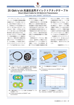
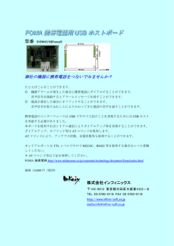
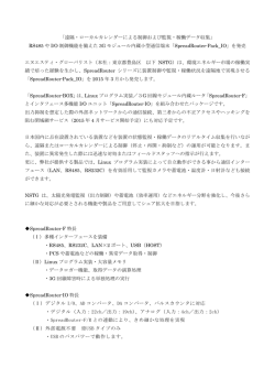
Network Servo System
SV-NET
コントローラ編
CONTROLLERS
TAMAGAWA SEIKI CO.,LTD
SV-NET CONTROLLER
プログラム開発は
SV-Programmer で簡単に
Program development ‒ made an easy job with our SV-Programmer
SV-NET サ ー ボ シ ス テ ム 制 御 の 司 令 塔、SV-NET コ ン ト ロ ー ラ「TA8440」と PC ア プ リ ケ ー シ ョ ン「SV
Programmer」がお客様にとってベストなモーションコントロールシステムの構築を可能にします。標準装備の
I/O を利用することでシーケンサ的プログラミングも可能となり、幅広いシーンに対応します。
Tamagawa’s“TA8440”series SV-NET controller ‒ the mainstay for our SV-NET servo system control ‒ and“SV Programmer”PC
application together allow customers to build a motion control system best suited for their needs. The use of I/O units, available as
standard, also enables sequential programming, allowing a wide range of tasks to be performed.
◆シーケンサ機能、I/O内蔵によりシーケンサレス制御可能(標準I/O各32点[拡張可能])
◆接点ベースのラダー言語ではなくモーションベースの言語で直感的なプログラミングが可能
◆加減速カーブを詳細に設定可能
◆ドライバの設定パラメータ、電流値まで一元管理
◆ Sequencer function and the built-in I/O units enable sequencer-less control (32 I/O points are a standard for each controller model ‒
expandable).
◆ Intuitive programming is possible thanks to the use of motion-based language rather than contact-based ladder language.
◆ It is possible to set detailed acceleration/deceleration curves.
◆ Capable of collective management, from driver setting parameters to current values.
SV-NET コントローラ
SV-NET Controller
CC リンク
CC links
デバイスネット
DeviceNet
アナログ接続
Analog connections
TA8440 シリーズ
TA8440 Series
2
PC アプリケーション
PC applications
豊富なコマンドで、スピーディーで柔軟なシステム開発を可能にします。
サンプルデータでデバックも簡単、立ち上げがスピーディーでスムーズに。
Plentiful commands enable speedy, flexible system development.
The use of sample data makes debugging easy, enabling speedy and smooth start-up.
プログラミングツール
試運転はジョグ運転
Programming tools
Jog operation for trial run
ユーザーインターフェイスに優れているた
め、操 作 は と て も 簡 単 で す。C言 語 対 応 の
ツールもあります。
各軸ごとに一定速度運転またはス
テップ運転を行うことができます。
ジョグ運転ではプログラムを製作す
ることなくモータを運転できます。
Our programming tools offer a superior
user interface, making operation very easy.
Tools compatible with C language are also
available.
For each axis, it is possible to
conduct constant-speed operation
or step operation. During jogging,
it is possible to drive the motor
without making a program.
グラフで動作確認サーボモニター
パラメータ一括管理
Servo monitor for graphical view of operation
Collective parameter management
各デバイスのパラ
メータを一括で管理
が 可 能。パ ラ メ ー タ
の設定値は印刷/保
存/読込が可能です。
位置、速度、電源をロギングして
グラフで表示します。
時間軸、測定軸スケールに可変可
能です。
The servo monitor outputs
graph displays by logging
position, speed and power
supply. Displays can be altered
to time axis and measurement
axis scales.
目次
Parameters for each device can be collectively managed. Parameter
setting values can be printed, stored, or loaded.
CONTENTS
コントローラ TA8440 特徴・仕様
4∼5p
SV Programmer 特徴・仕様
6∼7p
TA8440 Controller Features &Specifications
SV-Programmer Features &Specifications
SV-NET 回生・通信ユニット TA8413 シリーズ
8p
SV-NET 通信ユニット TA8433 シリーズ
8p
Master of SV-NET Ⅱ&Ⅲ
9p
SV トレーニングパック
9p
TA8413 SV-NET Regeneration/Communication Unit
TA8433 SV-NET Communication Unit
Master of SV-NET II & III
SV Training Package
ケーブル仕様
Cable Specifications
10p∼13p
3
SV-NET CONTROLLER
SV-NET CONTROLLER TA8440
CC-Link type
Device Net type
Analogue type
SV-NET コントローラ「TA8440」と PC アプリケーション「SV Programmer」が
モーションコントロールシステム構築を支援します。
SV-NET Controller "TA8440" and PC Software "SV Programmer" being the Mainstay of your Motion Control System
USB
USB
PC との接続は USB で簡単接続。
Easy USB connection to PC.
制御電源 (DC24V)
Control power (DC24V)
制御電源はコントローラからすべてのドライバへ SV-NET ケーブルで接続。
Control power is supplied from the controller to all the drivers via
SV-NET cables.
最大制御軸数 8 軸
Max. 8-axis control
TA8440 の主な機能
Main functions of TA8440
■SV-NET ポート ×1
■USB ポート ×1
■電源 DC24V
■I/O 32 点又は 64 点
■スタンドアロン動作可能
■最大接続数 8 軸
■8 軸 同期運転可能
■プログラムメモリー容量 640KB
■補間周期 4ms
■伝送周期 2ms
■
■
■
■
■
■
■
■
■
■
SV-NET port ×1
USB port ×1
Power supply DC24V
I / O 32 or 64 points
Stand-alone operation
Max. connectable axes : 8
8-axis synchronous operation
Program memory capacity 640KB
Interpolation cycle 4 ms
Transmission cycle 2 ms
最大 8 軸まで制御可能。また 8 軸まで同期運転が可能です。直線補間 (8 軸 )、
円弧補間 (2 軸 )、ヘリカル補間 (3 軸 ) 可能。
Up to 8 axes controllable. Also synchronous operation for 8 axes. Linear
interpolation (8 axes), circular interpolation (2 axes),
helical interpolation (3 axes)
スタンドアロン動作
Stand-alone operation
作成したプログラムにより、PC を接続せずに動作させることができます。
I/O を組み合わせることで柔軟なシステム構築が可能となります。
The system can operate on a prepared program without connecting PC.
Flexible system structuring possible by various I/O combinations.
I/O 標準装備
I/O interfaces up to 64 points
入力 16 点 出力 16 点、合計 32 点 (SVCC-I) と
入力 32 点 出力 32 点、合計 64 点 (SVCC-II) をラインアップ。
16 input points/16 output points : Total 32 points (SVCC-I)
32 input points/32 output points : Total 64 points (SVCC-II)
PC アプリケーション
PC application
■SV Programmer( プログラミングソフト )
■ SV Programmer (programming software)
プログラミングソフトは下記ホームページよりダウンロードすることがで
きます。( 無償 )
You can download the programming software from the following
website free of charge :
http://sv-net.tamagawa-seiki.com
付属品
Accessories
■TA8440 本体
■USB ケーブル (PC 接続用 )
■RS232 ケーブル
■ USB cable (for PC connection)
■ RS232C cable
TA8440 の各部の名称
Names of TA8440 parts
⑦SW-ID
①SV-NET
⑧HW-ID
②Power
③Status
④RS232C
⑨BOOT
⑤USB
4
⑥I/O
⑩PF No.
①SV-NET コネクタ
②Power 電源入力コネクタ
③Status LED
④RS232C バージョンアップ用 /タッチパネル接続用
⑤USB PC 接続用
⑥I/O コネクタ
⑦SW-ID 出荷時に設定
⑧HW-ID 出荷時に設定
⑨BOOT バージョンアップ時使用
⑩PF No. 出荷時に設定
①
②
③
④
⑤
⑥
⑦
⑧
⑨
⑩
SV-NET : CAN Connector
Power : Power input connector
Status : LED
RS232C : For upgrading firmware
and for touch panel connection
USB : For PC connection
I / O : Connector
SW-ID : Set at factory
HW-ID : Set at factory
BOOT : Used for upgrading firmware
PF No. : Set at factory
TA8440 Model Designation
製品種別
カバー色仕様
その他オプション
ソフト仕様
Cover color
Other option
Software specification
0:Black(standard)
2:Red
3:Silver
4:Green
5:Blue
6:White
0:標準
0:Standard
100:標準
100:Standard
基本タイプ
:I/Oボード1 枚
〃 :I/Oボード2 枚
〃 :I/Oボード4 枚
CC-Link 対応 :I/Oボード1 枚
〃 :I/Oボード2 枚
Device Net 対応:I/Oボード1 枚
〃 :I/Oボード2 枚
アナログ入出力対応:I/Oボード1 枚
〃
:I/Oボード2 枚
10 : SVCC-I (I/O×1)
20 : SVCC-II (I/O×2)
40 : SVCC- III (I/O×4)
21 : SVCC-CI (CC-Link+I/O×1)
31 : SVCC-CII (CC-Link+I/O×2)
22 : SVCC-DI (Device Net+I/O×1)
32 : SVCC-DII (Device Net+I/O×2)
23 : SVCC-AI (Analog+I/O×1)
33 : SVCC-AII (Analog+I/O×2)
38
42
4.2
51
55
SVCC-CI・DI・AI
(2)
SVCC-III
(2)
4.2
76
80
SVCC-CII・DII・AII
(2)
4.2
75
2
TA8440 Basic Specifications
ユニット仕様
モーション制御仕様
■制御軸数 最大 8 軸
■補間周期 4ms
■ Power input
DC24V±10%
Current consumption 0.3A Max.
■ SV-NET
Number of ports ×1
Communication protocol SV-NET
Physical layer:CAN
Control power output DC24V
■ USB
Number of ports ×1 for PC connection
■ I/O
1 port 32 points
(16 input points, 16 output points)
SVCC- I ×1 port
SVCC- II ×2 ports
■ Program memory capacity
640KB
■ RS232C
Number of ports ×1
Upgrade and for the touch panel
connection
Touch panel
・VT series
(Keyence)
・Digital Electronics Corp. Memorylink
・GOT series
(Mitsubishi)
耐環境仕様
■動作環境
0∼40℃ 90%RH 以下
結露なきこと
■保存温度 −10∼85℃
■対応規格 RoHS 指令対応
58
62
4.2
PC
×4
SV-NET
SV-NET
Driver
Motion control specifications
Software
■ PC application
SV Programmer
Environmental specifications
■
■
■
Operation environment
0 ∼ 40℃ 90%RH Max.
No condensation
Storage temperature −10 ∼ 85℃
Applicable standard RoHS Directive
■
■
■
USB cable (for PC connection)
RS232C Cable
SV Programmer
Installation CD for a charge is available.
製品及び付属品
タッチパネル
Touch
Panel
1 GND
2 CAN_L
3 SHELD
4 CAN_H
5 +24V
1 GND
2 NC
3 NC
4 +24V
×4
×4
×4
RS232C
許容電流
100mA
×4
許容電流
100mA
×4
許容電流
100mA
×4
許容電流
100mA
×4
Current
capacity
100 mA Max.
Current
capacity
100 mA Max.
Current
capacity
100 mA Max.
Current
capacity
100 mA Max.
4.2
(13.5)
External Connection Diagram
USB
Power
■ Number of control axes : 8 Max
■ Transmission cycle : 4ms
71
75
外部接続図
電源
Power
supply
ソフトウェア
■PC アプリケーション
SV Programmer
116
108
100
■電源入力
DC24V±10%
消費電流 0.3A 以下
■SV-NET
ポート数×1
通信プロトコル SV-NET
物理層:CAN
制御電源出力 DC24V
■USB
ポート数×1 PC 接続用
■I/O
1 ポート 32 点
( 入力 16 点 / 出力 16 点 )
SVCC-I×1 ポート
SVCC-II×2 ポート
■プログラムメモリー容量
640KB
■RS232C
ポート数×1
バージョンアップ及び
タッチパネル接続用
タッチパネル
・VT シリーズ
( キーエンス社製 )
・デジタル社メモリリンク
・GOT シリーズ
( 三菱社製 )
Unit specifications
116
108
100
TA8440 基本一覧
(2)
116
108
100
E
Product type
10:SVCC-I
20:SVCC-II
40:SVCC-III
21:SVCC-CI
31:SVCC-CII
22:SVCC-DI
32:SVCC-DII
23:SVCC-AI
33:SVCC-AII
SVCC-II
(2)
116
108
100
TA8440 N
SVCC-I
116
108
100
TA8440 形式一覧
1
2
3
4
5
6
7
8
9
10
11
12
13
14
15
16
17
18
19
20
21
22
23
24
25
26
27
28
29
30
31
32
33
34
35
36
37
38
39
40
I/O-1&I/O-2
入力用電源 24V IN 0-3
入力用電源 24V IN 4-7
Input power
IN 0
24V IN 0-3
IN 1
Input power
IN 2
24V IN 4-7
IN 3
IN 4
IN 5
IN 6
IN 7
入力用電源 24V IN 8-11
入力用電源 24V IN 12-15
Input power
IN 8
24V IN 8-11
IN 9
Input power
IN 10
24V IN12-15
IN 11
IN 12
IN 13
IN 14
IN 15
出力用電源グランド OUT 0-3
出力用電源グランド OUT 4-7
Output power
OUT 0
Ground OUT 0-3
OUT 1
Output power
OUT 2
Ground OUT 4-7
OUT 3
OUT 4
OUT 5
OUT 6
OUT 7
出力用電源グランド OUT 8-11
出力用電源グランド OUT 12-15
OUT 8
Output power
OUT 9
Ground OUT 8-11
OUT 10
Output power
OUT 11
Ground OUT12-15
OUT 12
OUT 13
OUT 14
OUT 15
Accessories
■TA8440 本体
■USB ケーブル (PC 接続用 )
■RS232C ケーブル
■SV Programmer
インストール CD は別途料金が必要です。
詳細はお問い合わせ下さい。
5
SV-NET CONTROLLER
SV Programmer
プログラミング
Programming
JOG 運転
Jog operation
サーボモニター
Servo monitor
パラメータ管理
Parameter management
豊富なコマンドが迅速かつ柔軟なシステム開発を可能にします。
Up-to-date programming with a rich supply of commands realizing a speedy and flexible system development for you !
プログラミングツール「プログラムグリッド」
Programming tool "Program Grid"
プログラミングは、専用モーション言語で作成します。
実際のプログラミングは、
ステップごとのプルダウンメニューからコマンド選
択し、
コマンドに対応した引数を入力するといった、簡単な操作を採用してい
ます。
Programming is done in Tamagawa's original language.
That is, you select a command from the pull-down menu in each step and
enter an argument incorrespondence to the command.
The up-to-date programming is quite easy.
グラフで動作確認「サーボモニター」
"Servo Monitor" for graphical view of operation
位置、速度、電流をロギングして
グラフで表示します。
時間軸、測定軸スケール可変。
Positions, speeds, and currents
are logged and displayed in
graphs.
Axes of the graphs are scalable as you like.
試運転は「ジョグ運転」
"Jog Operation" for trial run
各軸ごとに一定速度運転ま
たはステップ運転を行うこと
ができます。
ジョグ運転ではプログラムを
作成することなくモータを運
転できます。
Constant speed operation or
step operation can be
performed for each individual
axis.
In JOG operation, you can
operate the motor without
programming, just by selecting
menu.
6
SV Programmerの主な機能
Main Functions of SV Programmer
■プログラムグリッド
専用モーション言語
最大 5000ステップ
プログラムメモリー容量 640KB
変数領域 32KB
■ジョグ運転
一定速度運転、
ステップ運転が可能
オーバーライド機能が使用可能
■サーボモニター機能
測定項目
位置/速度/フィードバック電流
時間軸、測定軸スケール変更可能
■デバイスセットアップ
デバイス(ドライバ ) パラメータ管理
一覧表示/カテゴリ表示
パラメータ変更/保存
パラメータデータの読込/保存/印
刷等が可能
■コントローラセットアップ
SV-NETコントローラのパラメータ
情報を管理します。
一覧表示/分割表示
パラメータ変更/保存
パラメータデータの読込/保存/印
刷等が可能
■
■
■
■
■
Program Grid
Tamagawa's original language
Max. 5000 steps
Program memory capacity
640KB
Variables capacity 32KB
Jog operation
Constant speed operation and
step operation possible Override
function usable
Servo monitor function
Monitored items : Position,
speed, and feedback current
Time axis and measurement
axis scale changeable
Device setup
Device (driver) parameter
management
Display in list or in category
Changing and saving parameters
Upload/Download, storage,
printing of parameter data, etc.
Controller setup
Parameter information management
for SV-NET controller
Display in list or in category
Changing and saving parameters
Upload/Download, storage,
vprinting of parameter data, etc.
パラメータ一括管理「デバイスセットアップ」
"Device Setup" for collective parameter management
接続されているデバイス (ドライバ ) のパラメータを一括管理することがで
きます。パラメータの設定値は印刷/保存/読込が可能です。
カテゴリ表示
では制御モード、サーボコマンド、サーボゲインなどのパラメータが、
わかり
やすく配置しており調整時に適しています。
The parameters for the connected devices (drivers) can be managed
collectively.
The parameter settings can be loaded, stored, and printed. The category
display facilitates adjustments with its easy-to-understand display of
parameters such as control modes, servo commands, and servo gains.
特長的なコマンド
Unique programming commands
■複合コマンドで加減速パターンをユーザが積極的にカスタマイズ。台形パ
ターン、S 字カーブなどの移動パターンの他に、複合コマンドを使用するこ
とで、
ご使用の装置に最適な加減速パターンを作成可能です。
■The user can customize the acceleration /deceleration pattern, usingcomposite commands. In addition to movement patterns, such as
trapezoidal and S-curve patterns, you can create your own acceleration
/ deceleration patterns optimum for the system.
■コントローラやドライバの状態を確認するモニタコマンドは、指定したパラ
メータを変数に格納するコマンドです。
この機能によりコントローラ、
ドライバの状態に応じたプログラムを実行す
ることにより、柔軟なシステムを構築できます。
■Monitor commands for checking status of the controller or drivers set
specified data in variables.
You can use these variables in the program to make the motion so
flexible.
■変数の間接参照を使用することにより、
プログラミング効果を改善し、迅速
なシステム開発を可能にします。
■Use of indirect reference to variables enhances the efficiency of
programming.
You can accomplish a speedy system development.
基本仕様
Basic Specifications
■動作環境
対応機種 PC/AT 互換機
対応 OS Windows 2000,XP,Vista
必要メモリ 256MB 以上
ハードディスク 500MB 以上
■
PC environment
Applicable model
Applicable OS
Necessary memory
Hard disk
PC/AT compatible machine
Windows 2000, XP, Vista
256MB Min.
500MB Min.
■USB
USB 2.0 Full Speed
■プログラミング関連
言語
プログラム容量
プログラムステップ
ユーザタスク
■ USB
USB 2.0 Full Speed
多摩川精機オリジナル言語
640KB
最大 5000ステップ
最大 8 本
変数容量 32KB
変数タイプ 32bit 符号付き整数
(−2147483648∼2147483647)
代入/単項/加算/減算/
乗算/除算/剰余
論理演算
論理反転/論理積/
論理和/批他的論理和/論理シフト
ジャンプ命令 無条件ジャンプ/単項/論理積/
等号関係/不等号関係/以下関係/
以上関係/小関係/大関係
サブルーチン CALL 命令有り
Jump instructions
Subroutines
■モーション制御仕様
制御軸数 最大 8 軸
伝送周期 2ms
補間周期 4ms
補間機能 直線補間 (8 軸 )
円弧補間 (2 軸 )
ヘリカル補間 (3 軸 )
制御方式 位置制御/速度制御/電流制御
補正機能 電子ギア
指令単位 mm/deg( 位置制御時 )
加減速処理 S 字 台形制御方式
原点復帰機能 有り
ジョグ運転 有り
オーバーライド機能 有り
SV-NET 1 系統
■
算術演算
■
Programming specifications
Language
Tamagawa's original language
Program capacity
640KB
Program steps
Max. 5000 steps
User tasks Max. 8 tasks
Variables capacity 32KB
Variables type
32-bit signed integer
(−2147483648 ∼ 2147483647)
Unconditional jump, unary,
AND, equality sign,
inequality sign, less or equal,
more or equal, small, large
Call instruction available
Motion control specifications
Number of control axes
Max. 8
Transmission cycle
2ms
Interpolation cycle
4ms
Interpolation function Linear interpolation (8 axes) /
Circular interpolation (2 axes) /
Helical interpolation (3 axes)
Control system Position control, speed control,
current control
Compensation function Electronic gear
Command units mm/deg (in position control)
Acceleration/deceleration S-curve and trapezoidal control
Home position return function
Jog operation
Override function SV-NET
1 system
Arithmetic operation Substitution, unary, addition,
subtraction, multiplication,
division, remainder
Logical operation Logical inversion, logical
multiplication (AND), logical
addition (OR), exclusive OR,
logical shift
7
SV-NET CONTROLLER
SV-NET 回生・通信ユニット TA8413 シリーズ
SV-NET Regeneration & Communication Unit
回生作用からドライバ、モータを保護します。
Driver and motor protected against regenerative action
TA8413 形式一覧
TA8413 Model Designation
TA8413 回生・通信ユニット主な機能
Main Functions of TA8413 Regeneration &
Communication Unit
TA8413N
221:DC24V 用、SUMチェックあり、Net Monitorあり
With SUM check, With Net Monitor
242:DC48V 用、SUMチェックあり、Net Monitorあり
With SUM check, With Net Monitor
■回生保護機能
回生作用による駆動電圧の上昇を抑え、
ドライバ、
モータを保護します。
回生抵抗内蔵 DC24/48V 仕様ラインアップ。
■SV-NET 変換機能
RS232CをSV-NETに変換します。
■Master of SV-NET
パソコンアプリケーション
「Master of SV-NET」
と組み合わせることで
パソコンからドライバのパラメータ管理や簡易的な制御を行うことができ
ます。
■対応ドライバ
TA8410シリーズ
■
■
■
■
Regenerative protection function
Drivers and motors are protected by controlling the
rise of drive voltage due to regenerative action.
A lineup of DC24/48V specifications with built-in
regenerative resistor.
SV-NET conversion function
Conversion from RS232C to SV-NET
Master of SV-NET
PC application "Master of SV-NET" helps to
enable parameter management of drivers and simple
control from the personal computer.
Compatible driver TA8410 series
SV-NET 通信ユニット TA8433 シリーズ
SV-NET Communication Unit
RS232C 等から SV-NET ドライバの制御を可能にします。
Control of SV-NET drivers via RS232C/RS422/RS485
TA8433 形式一覧
TA8433 Model Designation
TA8433N□□1
通信方式 Communication method
1:RS-422
2:RS-485
シリアル通信プロトコル
Serial communication protocol
2:SUMチェックあり、Net Monitorあり
With SUM check, With Net Monitor
TA8433 シリーズ通信ユニット主な機能
Main Functions of TA8433
Communication Unit
■SV-NET 変換機能
RS232C/RS422/RS485をSV-NETに変換します。
■Master of SV-NET
パソコンアプリケーション
「Master of SV-NET」
と組み合わせることで
パソコンからドライバのパラメータ管理や簡易的な制御を行うことができ
ます。
■対応ドライバ
すべての SV-NETドライバ
■
■
■
8
SV-NET conversion function
Conversion from RS232C/RS422/RS485 to SV-NET
Master of SV-NET
PC application "Master of SV-NET" helps to
enable parameter management of drivers and
simple control from the personal computer.
Applicable drivers All SV-NET drivers
Master of SV-NETⅡ&Ⅲ
Master of SV-NETⅡ&Ⅲ
Master of SV-NETⅡ&Ⅲ 主な機能
Main Functions of Master of SV-NET Ⅱ&Ⅲ
■制御モード
位置制御、速度制御、電流制御を行えます。
■パラメータ管理
パラメータ一覧から読込、書込が行えます。
■簡易プログラム
20ステップ以内のプログラムを作成することができます。
■対応ドライバ
すべての SV-NETドライバ
■Master of SV-NET Ⅲ
「Ⅱ」
より・SUM チェック・ネットモニター機能に対応した PC アプリケー
ションです。
(※追加された機能については組み合わせ ( 接続機器のバージョン)により
使用できない場合があります。)
■ Control mode
Position control, Speed control, Current control
■ Parameter management
Reading and writing to / from parameter list
■ Simple programming
Programming in 20 steps Max. possible.
■ Applicable drivers
All SV-NET drivers
■ Master of SV-Net Ⅲ is the latest PC application upgraded from Ⅱ,
which includes new functions such as checksum, net monitor, etc.
(New functions may not be applicable depending on versions of
SV components in use.)
SV-NET トレーニングパック TA8425
SV-NET Training Pack TA8425
このトレーニングパックは家庭用 AC100V 電源と、
パソコンを接続すれば 3 軸のモータを運転する環境が揃っています。
With the AC 100V power outlet and a PC connected, this training pack creates an
environment for operating three axes of motors.
構成
■SV-NETコントローラ
TA8440×1
■ドライバ
TA8410×3
■モータ
TBL-iⅡ 50W TS4602×2
TBL-V 50W TS4742×1
■電源
AC100V 入力
DC24V 出力 2.5A
■付属品
電源ケーブル×1
USB ケーブル×1
CD-ROM×1
Configuration
■
■
■
■
■
SV-NET controller
TA8440 × 1
Driver
TA8410 × 3
Motor
TBL-i II 50W TS4602 × 2
TBL-V 50W TS4742 × 1
Power source
AC100V input
DC24V output 2.5A
Accessories
Power cable ×1
USB cable × 1
CD-ROM × 1
9
SV-NET CONTROLLER
Cables Specifications
(単位:mm)
EU9611
Controller Power Cable
+10%
7
形式
734-104(WAGO製)
L −0%
1
2
3
4
■長さ(L):0.1m∼20mまで指定可能。
長さ(L)
Model
(16.2)
コントローラ電源ケーブル
(Unit :mm)
(13.4)
length(L)
EU9611 N 0001 0.1m
N 0010
1m
N 0100 10m
Length (L) : 0.1m∼20m specifiable
SV-NETケーブル
EU9610
SV-NET Cables
● TA8410/TA8411/TA8413/TA8433用
形式
For TA8410/TA8411/TA8413/TA8433
5
4
3
2
1
(50)
L
(50)
734-105(WAGO製)
(φ7)
(19.7)
734-105(WAGO製)
形式表示 Model marking
デバイスネットケーブル Device net cable
(13.4)
長さ(L)
Model
1
2
3
4
5
length(L)
EU9610 N*010 1m
N*030 3m
N*050 5m
N*100 10m
■長さ(L):10cm単位で20mまで指定可能。N*001∼N*200 *=1:片側コネクタ無 *=2:両側コネクタ有 *=0:両側コネクタ無
Length(L) :Up to 20m specifiable in 10cm unit. N*001∼N*200 *=1 : Connector on one end,
*=2 : Connectors on both ends,
*= 0 : No connectors on both ends
■ケーブル長の公差について(N0***∼N7***共通)
ケーブル長にかかわらずマイナス公差は0とします。
プラス公差はケーブル長によりケーブル長×0.1とします。
例えば、
ケーブル長L=10cm 公差 + 1cm/-0cm
L= 1m + 10cm/-0cm
L= 10m +100cm/-0cm
Cable length tolerance (common to N0*** ~ N7***)
Minus tolerances are considered 0, regardless of the cable length.
Plus tolerances are calculated as a given cable length×0.1.
For example, cable length L = 10cm Tolerance + 1cm/-0cm
L = 1m + 10cm/-0cm
L = 10m + 100cm/-0cm
シリアル通信ケーブル
● TA8413/TA8433用
For TA8413/TA8433
+100
モジュラプラグ
(9.5)
①
⑥
10
Modular plug
(φ6.7)
L 0
(10.5)
EU6517
Serial Communication Cable
パソコン側
PC-side
D-SUB 9ピン RS232C 接続用
D-SUB 9 pins RS232C connection
17JE-13090-02(D8A)A-CG(JAE製) 17JE-13090-02(D8A)A-CG(JAE)
(15.4)
形式表示 Model marking
(32.3)
■
形式
Model
EU6517 N2
N3
N5
長さ(L)
length(L)
2m
3m
5m
(単位:mm)
● フラットケーブル
Flat CabIe
EU9642N0***
+10%
L −0%
ハウジング:HIF 3BA-40D-2.54R(ヒロセ)
フラットケーブル
Housing:HIF3BA-40D-2.54R(HIROSE)
2
4
6
8
10
12
14
16
18
20
22
24
26
28
30
32
34
36
38
40
EU9642
PF Cable for controller
Flat Cable
+10%
L −0%
EU9642N1***
ハウジング:HIF 3BA-40D-2.54R(ヒロセ)
Housing:HIF 3BA-40D-2.54R(HIROSE)
2
4
6
8
10
12
14
16
18
20
22
24
26
28
30
32
34
36
38
40
1
3
5
7
9
11
13
15
17
19
21
23
25
27
29
31
33
35
37
39
1
3
5
7
9
11
13
15
17
19
21
23
25
27
29
31
33
35
37
39
(56)
コントローラ用PFケーブル
(Unit :mm)
(7)
(16)
● シールドケーブル
EU9642N5***
Shielded Cable
F1.25-3.5(大同端子製造)相当品
ハウジング:HIF 3BA-40D-2.54R(ヒロセ)
F1.25-3.5(DAIDO SOLDERLESS
TERMINAL MFG) EquivaIent
Housing:HIF 3BA-40D-2.54R(HIROSE)
1
3
5
7
9
11
13
15
17
19
21
23
25
27
29
31
33
35
37
39
ハウジング:HIF 3BA-40D-2.54R(ヒロセ)
Housing:HIF 3BA-40D-2.54R(HIROSE)
2
4
6
8
10
12
14
16
18
20
22
24
26
28
30
32
34
36
38
40
シールドケーブル
Shielded Cable
(φ12)
2
4
6
8
10
12
14
16
18
20
22
24
26
28
30
32
34
36
38
40
EU9642N6***
+20
0
200
+20
0
200
1
3
5
7
9
11
13
15
17
19
21
23
25
27
29
31
33
35
37
39
+20
0
200
形式
Model
長さ(L)
length(L)
EU9642 N*001 0.1m
N*010
1m
N*030
3m
N*050
5m
11
SV-NET CONTROLLER
Cables Specifications
ディジーチェーン接続用ケーブル
EU9610
Daisy-chain connection cable
熱収縮チューブ
EU9610N7***E***
Heat-shrinkable tube
終端抵抗
Terminating resistor
734-105(WAGO)
734-105(WAGO)
左端
※1
デバイスネットケーブル
Left end
右端
Right end
Device net cable
1
2
3
4
5
734-105(WAGO)
1
2
3
4
5
1
5
(20)
(20)
L
L1
形式表示
● 接続図
左端(コントローラ接続)
(ドライバ接続)
1
2
CAN+
4
+24V
5
Right end (driver connection)
734-105(WAGO)
734-105(WAGO)
黒 Black
1
青 Blue
ドレンワイヤ
SHIELD 3
右端(ドライバ接続)
(driver connection)
734-105(WAGO)
CAN-
(20)
Connections
Left end (controller connection)
GND
Model indication
L2 ※2 ( ≦ 20000 )
(20)
2
3
Drain wire
白White
4
赤Red
5
黒 Black
黒 Black
青 Blue
ドレンワイヤ
青 Blue
白White
白 White
赤Red
赤
1 GND
2 CAN-
Drain wire
3 SHIELD
4 CAN+
5 +24V
Red
ドレンワイヤ
Drain wire
終端抵抗 Terminating resistor
1/4W 120Ω
※1 リード線が2本まとめてコネクタに入る箇所には、
ツインフェルール216-202
(WAGO)
を使用しています。
*1: A twin ferrule 216-202 (WAGO) will be used where two leads enter a connector together.
※2 ケーブル全長 L2は20m
(20000mm)
以下で指定します。( L1=(40)を含む )
*2: Total cable length L2 will be specified to be less than 20m (20000mm).(Includes L1=(40).)
EU9610N7010E109の全長計算;
L2= L×(コネクタ個数-1) + L1×(コネクタ個数-1)
Total length calculation for EU9610N7010E109:
L2 = L×(No. of connectors−1) + L1×(No. of connectors−1)
= 1000×8 + 40×8
= 8320 mm
ケーブル全長 L2は公差を含まないで計算しますので実際の製品の全長は20m(20000mm)
を超える場合があります。
Total length L2 is calculated excluding tolerance, so the actual total length of a product may exceed 20m (20000mm).
● 形式表示方法
Model indication method
EU 9610 N 7***E***
①
② ③
①ケーブル長 L
②終端抵抗 上図参照。
(1/4W 120Ω)
① Cable length L
指定
長さ
000
0.09m
001
0.1m
Designation Length
010
1m
098
9.8m
③コネクタ数
② Terminating resistor : See Fig. above. (1/4W 120Ω)
特記事項
Remark
0.1m
(10cm)
単位で指定。
To be designated in units of 0.1m
(10cm).
指定
終端抵抗 取付位置
Designation Terminating resistor mounting position
0
1
なし None
右端コネクタ
2
左端コネクタ
Right-end connector
Left-end connector
③ No. of connectors
特記事項
Remark
・2-4ピン間に挿入
・終端抵抗は信号ライン両端に必要です。
弊社コントローラは、終端抵抗を内蔵
していますので、本ケーブルの終端抵
抗接続コネクタ側には、必ずドライバ
を接続してください。
• To be inserted between 2 pin and 4 pin.
• Terminating resistors need to be at both ends of the
signal line. Since our controllers have built-in
terminating resistors, make sure to connect the driver
to the cable’
s terminating resistor connection side.
12
指定
コネクタ数
03
3
09
9
Designation No. of connectors
特記事項
Remark
ディジーチェーン接続用ケーブル
EU9610N0***
(7)
EU9610
Daisy-chain connection cables
注)
***はケーブル長L指定。下表参照。 Note: ***denotes cable length (L) designation. See table below.
ドライバ増設時に、
コネクタ間のケーブルとしてご使用いただけます。 EU9610N0 can be used as a cable between connectors when the number of drivers is increased.
(50)
(50)
L
(7)
デバイスネットケーブル
DeviceNet cable
形式表示
● 接続図
Connections
黒 Black
1
GND
青 Blue
CAN- 2
ドレンワイヤ
SHIELD 3 Drain wire
白 White
CAN+ 4
赤 Red
+24V 5
EU9610N1***
(7)
Model indication
1 GND
2 CAN3 SHIELD
4 CAN+
5 +24V
注)
***はケーブル長L指定。下表参照。Note: ***denotes cable length (L) designation. See table below.
ドライバ1台増設時に、
ご使用いただけます。This cable can be used when one driver is added.
(50)
(50)
L
デバイスネットケーブル
DeviceNet cable
1
2
3
4
5
形式表示
Model indication
● 接続図
Connections
GND
1
黒 Black
1 GND
青 Blue
2 ドレンワイヤ
Drain wire
SHIELD 3
白 White
CAN+ 4
赤 Red
+24V 5
2 CAN-
CAN-
EU9610N2***
734-105(WAGO)
734-105(WAGO)
3 SHIELD
4 CAN+
5 +24V
注)
***はケーブル長L指定。下表参照。 Note: ***denotes cable length (L) designation. See table below.
(50)
(50)
L
デバイスネットケーブル
DeviceNet cable
1
2
3
4
5
1
2
3
4
5
形式表示
734-105(WAGO)
Model indication
● 接続図
734-105(WAGO)
GND
1
CAN-
2
SHIELD 3
CAN+
4
+24V
5
734-105(WAGO)
黒 Black
1 GND
青 Blue
ドレンワイヤ
2 CAN-
Drain wire
白
White
赤
Red
■ケーブル長Lの指定方法
(N0***∼N2***)
形式のN番で指定します。
単位を10cmとしN番指定範囲をN*001∼N*200とします。
ケーブル長の指定範囲は10cm∼2000cm(20m)となります。
例えば、
ケーブル長L=10cm 型式 EU9610N*001
L= 1m EU9610N*010
L= 10m EU9610N*100
■
734-105(WAGO)
Connections
How to designate cable length L (N0*** ~ N2***)
Length of each cable will be designated by its model number (N).
Length will be given in units of 10cm and the model number designation
range will be N*001 ~ N*200.
Cable length designation ranges between 10cm ~ 2000cm (20m).
For example, cable length L = 10cm Model: EU9610N*001
L = 1m EU9610N*010
L = 10m EU9610N*100
3 SHIELD
4 CAN+
5 +24V
■ケーブル長の公差について(N0***∼N7***共通)
ケーブル長にかかわらずマイナス公差は0とします。
プラス公差はケーブル長によりケーブル長×0.1とします。
例えば、
ケーブル長L=10cm 公差 + 1cm/-0cm
L= 1m + 10cm/-0cm
L= 10m +100cm/-0cm
■
Cable length tolerance (common to N0*** ~ N7***)
Minus tolerances are considered 0, regardless of the cable length.
Plus tolerances are calculated as a given cable length×0.1.
For example, cable length L = 10cm Tolerance + 1cm/-0cm
L = 1m + 10cm/-0cm
L = 10m + 100cm/-0cm
13
SV-NET CONTROLLER
Memo
14
15
安全に関するご注意
!
販売会社
多摩川精機販売株式会社
●正
しく安全にお使いいただくため、
ご使用の前に「安全
上のご注意」をよくお読みください。
■国内営業本部
本 社 〒395-0063 長野県飯田市羽場町1丁目3番1号
TAMAGAWA TRADING CO.,LTD.
製品の保証
・東 京 営 業 所
〒144-0054 東京都大田区新蒲田3丁目19番9号
TEL
(03)
3731-2131
FAX
(03)
3738-3134
・北関東営業所
〒330-0071 埼玉県さいたま市浦和区上木崎1-11-1 与野西口プラザビル3F
TEL
(048)
833-0733
FAX
(048)
833-0766
・八王子営業所
〒191-0011 東京都日野市日野本町2丁目15番1号 セントラルグリーンビル2F
TEL
(042)
581-9961
FAX
(042)
581-9963
・神奈川営業所
〒252-0804 神奈川県藤沢市湘南台3丁目15番5号 2F
TEL
(0466)
41-1830
FAX
(0466)
41-1831
・名古屋営業所
〒486-0916 愛知県春日井市八光町5丁目10番地
TEL
(0568)
35-3533
FAX
(0568)
35-3534
・中 部 営 業 所
〒444-0837 愛知県岡崎市柱1丁目2-1 HAKビル3F-B
TEL
(0564)
71-2550
FAX
(0564)
71-2551
・大 阪 営 業 所
〒532-0011 大阪市淀川区西中島5丁目6番24号 大阪浜美屋ビル401号室
TEL
(06)
6307-5570
FAX
(06)
6307-3670
・福 岡 営 業 所
〒812-0011 福岡県福岡市博多区博多駅前4丁目3番3号 博多八百治ビル6F
TEL
(092)
437-5566
FAX
(092)
437-5533
TEL
(03)
3731-2131
FAX
(03)
3738-3134
■開発営業本部
・特機営業部
(東京営業所)
〒144-0054 東京都大田区新蒲田3丁目19番9号
・車載営業部
(北関東営業所)
〒330-0071 埼玉県さいたま市浦和区上木崎1-11-1 与野西口プラザビル3FTEL
(048)
833-0733
FAX
(048)
833-0766
(中部営業所)
〒444-0837 愛知県岡崎市柱1丁目2-1 HAKビル3F-B
FAX
(0564)
71-2551
TEL
(0564)
71-2550
・ATLAS営業部
(東京営業所)
〒144-0054 東京都大田区新蒲田3丁目19番9号
TEL
(03)
3731-2131
FAX
(03)
3738-3134
・TUG-NAVI営業部
(名古屋営業所)
〒486-0916 愛知県春日井市八光町5丁目10番地
TEL
(0568)
35-3533
FAX
(0568)
35-3534
・鉄道営業部
(東京営業所)
〒144-0054 東京都大田区新蒲田3丁目19番9号
TEL
(03)
3731-2131
FAX
(03)
3738-3134
(大阪営業所)
〒532-0011 大阪市淀川区西中島5丁目6番24号 大阪浜美屋ビル401号TEL
(06)
6307-5570
FAX
(06)
6307-3670
・MEMS営業部
〒395-0063 長野県飯田市羽場町1丁目3番1号
TEL
(0265)
56-5424
FAX
(0265)
56-5427
・バイオ営業部
〒395-0063 長野県飯田市羽場町1丁目3番1号
TEL
(0265)
56-5421
FAX
(0265)
56-5426
・開発営業部
〒395-0063 長野県飯田市羽場町1丁目3番1号
TEL
(0265)
56-5424
FAX
(0265)
56-5427
製品の無償保証期間は出荷後一年とします。ただし、お客様の
故意または過失による品質の低下を除きます。なお、品質保持
のための対応は保証期間経過後であっても、弊社は誠意をもっ
ていたします。弊社製品は、製品毎に予測計算された平均故障
間隔
(MTBF)
は極めて長いものでありますが、予測される故障
率は零(0)
ではありませんので弊社製品の作動不良等で考えら
れる連鎖または波及の状況を考慮されて、事故回避のため多重
の安全策を御社のシステムまたは/および製品に組み込まれる
ことを要望いたします。
■本カタログのお問い合わせは下記へお願いします。
・商品のご注文は、担当営業本部またはお近くの営業所までお問い
合わせください。
・技術的なお問い合わせは、
モーションコントロール研究所
技術課 直通 TEL
(0178)
21-2613
FAX
(0178)
21-2617
■Overseas Sales Department
Head quarters:1-3-1, HABA-cho, IIDA-City, NAGANO-Pref, 395-0063. JAPAN
PHONE:+81-265-56-5423 FAX:+81-265-56-5427
■各種お問い合わせ
〒395-0063 長野県飯田市羽場町1丁目3番1号
TEL
(0265)
56-5421,5422
FAX
(0265)
56-5426
製造会社
■本社・第1事業所 〒395-8515
■第 2 事 業 所 〒395-8520
■第 3 事 業 所 〒399-3303
■八 戸 事 業 所 〒039-2245
■八戸事業所福地第1工場 〒039-0811
■八戸事業所福地第2工場 〒039-0811
■八戸事業所三沢工場 〒033-0134
■東 京 事 務 所 〒144-0054
長野県飯田市大休1879
TEL
(0265)
21-1800
FAX
(0265)
21-1861
長野県飯田市毛賀1020
TEL
(0265)
56-5411
FAX
(0265)
56-5412
長野県下伊那郡松川町元大島3174番地22
TEL
(0265)
34-7811
FAX
(0265)
34-7812
青森県八戸市北インター工業団地1丁目3番47号
TEL
(0178)
21-2611
FAX
(0178)
21-2615
青森県三戸郡南部町大字法師岡字勘右衛門山1-1
TEL
(0178)
60-1050
FAX
(0178)
60-1155
青森県三戸郡南部町大字法師岡字仁右エ門山3-23
TEL
(0178)
60-1560
FAX
(0178)
60-1566
青森県三沢市大津2丁目100-1
TEL
(0176)
50-7161
FAX
(0176)
50-7162
東京都大田区新蒲田3丁目19番9号
TEL
(03)
3738-3133
FAX
(03)
3738-3134
A COMPANY OF TAMAGAWA SEIKI CO.,LTD.
■Overseas Sales Department
Headquarters:
1-3-1 Haba-cho, Iida, Nagano Pref. 395-0063 Japan
PHONE : +81-265-56-5423
FAX : +81-265-56-5427
●インターネットホームページ http://www.tamagawa-seiki.co.jp
本カタログに記載された内容は予告なしに変更することがありますので御了承ください。
T12-1684N1 2,000 部.再版印刷.2013年4月1日.
本カタログの記載内容は2013年4月現在のものです。
All Specifications are subject to change without notice.
T12-1684N1. 2013.4
© Copyright 2026 Paperzz