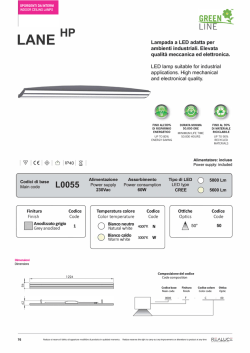
ENGLISH 8.2 (0.32) TEACH DH = (n x RM) – RM RM 4a 1 2 3 ON Q RM L = DH + RM + 33 (1.30) 7 3 7 1 2 3 ON Q Func Optimum light reception / Lichtempfang optimal 3 4 44.5 (1.75) 4 1 No light 1 Light reception 2 received / 2 not optimum / 3 3 kein Lichtempfang ON ON nicht optimal Q Lichtempfang Q Func Activate alignment Func Activate alignment aid and align aid and check light sensors / path / Ausrichthilfe Ausrichthilfe aktivieren und aktivieren und Sensoren ausrichten Lichtweg überprüfen 1 2 3 ON Q 8.6 (0.34) 100 (3.94) 1.2 1 2 3 ON Q Ø 9 (0.35) 1 s... 5 s TEACH All dimensions in mm (inch) / Alle Maße in mm 1 2 3 ON Q Parallel beam active / Parallelstrahl aktiv 1 s... 5 s 4b Alignment aid active / Ausrichthilfe aktiv 1 2 3 ON Q TEACH <1s 1 2 3 ON Q TEACH 1 s... 5 s TEACH Alignment aid inactive / Ausrichthilfe inaktiv 1 2 3 ON Q 1 s... 5 s M8 SICK AG, Erwin-Sick-Strasse 1, D-79183 Waldkirch TEACH TEACH After 10 s automatically in RUN mode / nach 10 s automatisch in RUN-Mode 1 2 3 ON Q Multiple scan active / Kreuzstrahl aktiv <1s 1 2 3 ON Q After 10 s automatically in RUN mode / nach 10 s automatisch in RUN-Mode After 10 s automatically in RUN mode / nach 10 s automatisch in RUN-Mode (0.05) 100 (3.94) 5 M8 More representatives and agencies at www.sick.com ∙ Subject to change without notice ∙ The specified product features and technical data do not represent any guarantee. Weitere Niederlassungen finden Sie unter www.sick.com ∙ Irrtümer und Ä nderungen vorbehalten ∙ Angegebene Produkteigenschaften und technische Daten stellen keine Garantieerklärung dar. Plus de représentations et d’agences à l’adresse www.sick.com ∙ Sujet à modification sans préavis ∙ Les caractéristiques de produit et techniques indiquées ne constituent pas de déclaration de garantie. Para mais representantes e agências, consulte www.sick.com ∙ Alterações poderão ser feitas sem prévio aviso ∙ As características do produto e os dados técnicos apresentados não constituem declaração de garantia. Altri rappresentanti ed agenzie si trovano su www.sick.com ∙ Contenuti soggetti a modifiche senza preavviso ∙ Le caratteristiche del prodotto e i dati tecnici non rappresentano una dichiarazione di garanzia. Más representantes y agencias en www.sick.com ∙ Sujeto a cambio sin previo aviso ∙ Las características y los datos técnicos especificados no constituyen ninguna declaración de garantía. 欲了解更多代表机构和代理商信息,请登录 www.sick.com ∙ 如有更改 , 不另行通知 ∙ 对所给出的产品特性和技术参数 的正确性不予保证。 その他の営業所は www.sick.com よりご覧ください ∙ 予告なし に変更されることがあります ∙ 記載されている製品機能およ び技術データは保証を明示するものではありません。 TEACH > 5 s/> 30s if keylock active /wenn Tastensperre aktiv 2 Ø 9 (0.35) 5 1 2 3 ON Q Func TEACH 2 DH = (n x RM) – RM Österreich Phone +43 (0)22 36 62 28 8-0 Norge Phone +47 67 81 50 00 Polska Phone +48 22 837 40 50 România Phone +40 356 171 120 Russia Phone +7-495-775-05-30 Schweiz Phone +41 41 619 29 39 Singapore Phone +65 6744 3732 Slovenija Phone +386 (0)1-47 69 990 South Africa Phone +27 11 472 3733 South Korea Phone +82 2 786 6321/4 Suomi Phone +358-9-25 15 800 Sverige Phone +46 10 110 10 00 Taiwan Phone +886-2-2375-6288 Türkiye Phone +90 (216) 528 50 00 United Arab Emirates Phone +971 (0) 4 8865 878 USA/México Phone +1(952) 941-6780 Configuration mode / Konfigurations-Mode: RUN mode / RUN-Mode 8.5 1.2 (0.98) (0.33) 25 (0.05) 8.5 1.2 (0.05) Sender / Sender 1 1 Smart-Gate-Sensor Please find detailed addresses and additional representatives and agencies in all major industrial nations at www.sick.com 8.2 (0.32) Sender / Sender 4 Teach-in mode / Teach-in-Mode: 1 s... 5 s SGS Australia Phone +61 3 9457 0600 Belgium/Luxembourg Phone +32 (0)2 466 55 66 Brasil Phone +55 11 3215-4900 Canada Phone +1(952) 941-6780 Ceská Republika Phone +420 2 57 91 18 50 China Phone +86 4000 121 000 +852-2153 6300 Danmark Phone +45 45 82 64 00 Deutschland Phone +49 211 5301-301 España Phone +34 93 480 31 00 France Phone +33 1 64 62 35 00 Great Britain Phone +44 (0)1727 831121 India Phone +91–22–4033 8333 Israel Phone +972-4-6801000 Italia Phone +39 02 27 43 41 Japan Phone +81 (0)3 3358 1341 Magyarország Phone +36 1 371 2680 Nederlands Phone +31 (0)30 229 25 44 Receiver / Empfänger 1.2 1 The sensor SGS has one switching output: Q: dark-switching, if light interrupted, output HIGH. Connect and secure cable receptacle tension-free. Connect cables. 2 Mount sender and receiver with SICK brackets opposite each other and align roughly. Adjust for scanning range (see technical data). Connect sender and receiver to operating voltage. 3 Legend: LED off, LED on, LED blinking Teach-in mode: – Press teach-in button 1 to 5 s: LEDs 1, 2, 3, ON (green), Q (yellow) and Func (red) light up: Optimum light reception. LED Q (yellow) and Func (red) light up: Light reception not optimized: Activate alignment aid in configuration mode and align sensors, until as many LEDs as possible light up. Func (red) lights up: No light received: Check light path (has to be free), activate alignment aid in configuration mode and align or clean sensors. After 10 s the sensor automatically switches to RUN mode. LEDs ON (green) and Q (yellow) light up. 4 Configuration mode: 4a Activate multiple scan: – Press teach-in button > 5 s: LED 1 blinks, LED 2, 3, ON (green), Q (yellow) light up. Activate parallel beam: – Press teach-in button < 1 s: LED 1 blinks, LED 2, 3, ON (green) light up, Q (yellow) off. 4b Activate alignment aid: – Press teach-in button between 1 s and 5 s: LED 1 lights up, LED 2 blinks, LED 3, ON (green), Q (yellow) light up. Deactivate alignment aid: – Press teach-in button < 1 s: LED 1 lights up, LED 2 blinks, LED 3, ON (green) light up, Q (yellow) off. 4c Switching Output Q1: – Press teach-in button between 1 s and 5 s: LED 1, 2 light up, LED 3 blinks, ON (green) lights up, Q (yellow) off. Switching Output Q1: – Press teach-in button < 1 s: LED 1, 2 light up, LED 3 blinks, ON (green), Q (yellow) light up. 4d Activate auto teach-in: – Press teach-in button between 1 s and 5 s: LED 1, 2, 3 light up, ON (green) blinks, Q (yellow) lights up. Deactivate auto teach-in: – Press teach-in button < 1 s: LED 1, 2, 3 light up, ON (green) blinks, Q (yellow) off. 4e Activate keylock: – Press teach-in button between 1 s and 5 s: LED 1 lights up, LED 2, 3, ON (green) blink, Q (yellow) lights up. Deactivate keylock: – Press teach-in button < 1 s: LED 1 lights up, LED 2, 3, ON (green) blink, Q (yellow) off. 4f Activate default settings: – Press teach-in button between 1 s and 5 s: LED 1 blinks, LED 2 lights up, LED 3, ON (green) blink, Q (yellow) lights up. Deactivate default settings: – Press teach-in button < 1 s: LED 1 blinks, LED 2 lights up, LED 3, ON (green) blink, Q (yellow) off. Switch to RUN mode: – Press teach-in button > 5 s or after 30 s (if not stored) automatically: ON (green) and Q (yellow) light up. 4g Switching Output Q2 (only types with second switching output): – Press teach-in button between 1 s and 5 s: LED 1, 2 blink, LED 3 lights up, ON (green) blinks, Q (yellow) off. Switching Output Q2: – Press teach-in button < 1 s: LED 1, 2 blink, LED 3 lights up, ON (green) blinks, Q (yellow) lights up. 4h Activate Muting: – Press teach-in button between 1 s and 5 s: LED 1, 2, 3 blink, ON (green), Q (yellow) light up. Deactivate Muting: – Press teach-in button < 1 s: LED 1, 2, 3 blink, ON (green) lights up, Q (yellow) off. Switch to RUN mode: – Press teach-in button > 5 s or after 30 s (if not stored) automatically: ON (green) and Q (yellow) light up. 4i Note: The smart light grids are only configurable via teach-in button. Beams are muted with the muting function. Sender / Sender (0.05) Starting operation (0.98) -------------------------------------------------------------- 8012912.X902 0513 CV ------------------------------------------------------------ L = DH + RM + 33 (1.30) The Smart Light Grid SGS is an opto-electronic sensor, which operates using a transmitter unit and receiver unit. It is used for optical, non-contact detection of objects, animals, and people. 25 BZ int39 Proper use Sender / Sender (0.33) Receiver / Empfänger Safety Specifications >> No safety component in accordance with EU machine guidelines. >> Faulty switching can occur, for example, due to: reflections, soiling, glare, malfunction of individual components or interference from electromagnetic fields. >> Read the operating instructions before starting operation. >> Connection, assembly, and settings only by competent technicians. >> Protect the device against moisture and soiling when operating. 3 A Flat without stabilizer / Flat ohne Stabilisator Smart Light Grid (SLG) for standard applications Operating instructions Legend / Legende: All dimensions in mm (inch) / Alle Maße in mm 1 2 3 ON Q Func 4c 1 2 3 ON Q green / grün green / grün green / grün green / grün Switching output Q1 / Schaltausgang Q1 TEACH Q <1s yellow / gelb red / rot TEACH 1 s... 5 s TEACH B M8 or / oder M12 1 2 3 ON Q Switching output Q1 / Schaltausgang Q1 Q 1 s... 5 s Sender / Sender Receiver / Empfänger Sender / Sender 4d 1 2 3 ON Q Receiver / Empfänger Auto teach active / Auto-Teach aktiv TEACH AUTO TEACH <1s TEACH 1 s... 5 s TEACH 1 2 3 ON Q Auto teach inactive / Auto-Teach inaktiv AUTO TEACH 1 s... 5 s brn 1 wht 2 blu 3 blk 4 L+ brn 1 Test wht 2 M blu 3 NC blk 4 L+ brn 1 Teach wht 2 M blu 3 Q blk 4 L+ brn 1 Test wht 2 M blu 3 NC blk 4 1 2 3 ON Q L+ 4e Keylock active / Tastensperre aktiv TEACH <1s Teach M TEACH Q 1 s... 5 s TEACH 1 2 3 ON Q Keylock inactive / Tastensperre inaktiv 1 s... 5 s 4f C 1 2 3 ON Q Maintenance 25% SICK sensors barriers are maintenance-free. We recommend doing the following regularly: - clean the external lens surfaces - check the screw connections and plug-in connections. No modifications may be made to devices. 50% Default settings active / Standardwerte aktiv TEACH <1s 25% TEACH 1 s... 5 s TEACH TEACH 1 2 3 ON Q Default settings inactive / Standardwerte inaktiv 1 s... 5 s 1 s... 5 s TEACH DEUTSCH Smart Light Grid (SLG) für Standard-Applikationen Betriebsanleitung Sicherheitshinweise >> Kein Sicherheitsbauteil gemäß EU-Maschinenrichtlinie. >> Fehlschaltungen können auftreten, z. B. durch: Umspiegelungen, Verunreinigung, Blendung, Ausfall einzelner Komponenten, bei Störungen durch elektromagnetische Felder. >> Vor der Inbetriebnahme die Betriebsanleitung lesen. >> Anschluss, Montage und Einstellung nur durch Fachpersonal. >> Gerät bei Inbetriebnahme vor Feuchte und Verunreinigung schützen. Bestimmungsgemäße Verwendung Das Einweg-Lichtgitter SGS ist ein optoelektronischer Sensor, der mit einer Sende- und Empfangseinheit arbeitet. Es wird zum optischen, berührungslosen Erfassen von Sachen, Tieren und Personen eingesetzt. 4h M uting aktivieren: – Teach-in-Knopf zwischen 1 s und 5 s drücken: LED 1, 2, 3 blinken, ON (grün), Q (gelb) leuchtet. Muting deaktivieren: –Teach-in-Knopf < 1 s drücken: LED 1, 2, 3 blinken, ON (grün) leuchtet, Q (gelb) aus. Wechsel in RUN-Modus: – Teach-in-Knopf > 5 s drücken oder automatisch nach 30 s (dann nicht abgespeichert): ON (grün) und Q (gelb) leuchten. 4i H inweis: Die Smart Light Grids sind nur über Teach-in-Knopf konfigurierbar. Wartung SICK-Lichtschranken sind wartungsfrei. Wir empfehlen, in r egelmäßigen Abständen – die optischen Grenzflächen zu reinigen, – Verschraubungen und Steckverbindungen zu überprüfen. Veränderungen an Geräten dürfen nicht vorgenommen werden. > 5 s or after / oder nach 30 s (if not stored) automatically in RUN mode / (nicht gespeichert) automatisch in RUN-Mode 1 2 3 ON Q 1 Q2 2 Inbetriebnahme 1 2 Der Sensor SGS hat einen Schaltausgang: Q: dunkelschaltend, bei Lichtunterbrechung Ausgang HIGH. Leitungsdose spannungsfrei aufstecken und festschrauben. Leitungen anschließen. Sender und Empfänger mit SICK-Halterungen gegenüberliegend montieren und ausrichten. Dabei Reichweite beachten (s. technische Daten). Sender und Empfänger an Betriebsspannung legen. 3 Legende: LED aus, LED an, LED blinkt Teach-in-Mode: – Teach-in-Knopf 1 bis 5 s drücken: LEDs 1, 2, 3, ON (grün), Q (gelb) und Func (rot) leuchten: Lichtempfang optimal. LED Q (gelb) und Func (rot) leuchten: Lichtempfang nicht optimal: Ausrichthilfe im Konfigurations-Mode aktivieren und Sensoren ausrichten, bis möglichst viele LEDs leuchten. Func (rot) leuchtet: kein Lichtempfang. Lichtweg überprüfen (muss frei sein), Ausrichthilfe im Konfigurations-Mode aktivieren und Sensor neu justieren bzw. reinigen. Nach 10 s wechselt der Sensor automatisch in den RUN-Mode und die LEDs ON (grün) und Q (gelb) leuchten. 4 Konfigurations-Mode: 4a Kreuzstrahl aktivieren: – Teach-in-Knopf > 5 s drücken: LED 1 blinkt, LED 2, 3, ON (grün), Q (gelb) leuchten. Parallelstrahl aktivieren: – Teach-in-Knopf < 1 s drücken: LED 1 blinkt, LED 2, 3, ON (grün) leuchten, Q (gelb) aus. 4b Ausrichthilfe aktivieren: – Teach-in-Knopf zwischen 1 s und 5 s drücken: LED 1 leuchtet, LED 2 blinkt, LED 3, ON (grün), Q (gelb) leuchten. Ausrichthilfe deaktivieren: – Teach-in-Knopf < 1 s drücken: LED 1 leuchtet, LED 2 blinkt, LED 3, ON (grün) leuchten, Q (gelb) aus. 4c Schaltausgang Q1: – Teach-in-Knopf zwischen 1 s und 5 s drücken: LED 1, 2 leuchten, LED 3 blinkt, ON (grün) leuchtet, Q (gelb) aus. Schaltausgang Q1: – Teach-in-Knopf < 1 s drücken: LED 1, 2 leuchten, LED 3 blinkt, ON (grün), Q (gelb) leuchten. 4d Auto-Teach-in aktivieren: – Teach-in-Knopf zwischen 1 s und 5 s drücken: LED 1, 2, 3 leuchten, ON (grün) blinkt, Q (gelb) leuchtet. Auto-Teach-in deaktivieren: – Teach-in-Knopf < 1 s drücken. LED 1, 2, 3 leuchten, ON (grün) blinkt, Q (gelb) aus. 4e Tastensperre aktivieren: – Teach-in-Knopf zwischen 1 s und 5 s drücken: LED 1 leuchtet, LED 2, 3, ON (grün) blinken, Q (gelb) leuchtet. Tastensperre deaktivieren: – Teach-in-Knopf < 1 s drücken: LED 1 leuchtet, LED 2, 3, ON (grün) blinken, Q (gelb) aus. 4f Standardeinstellungen aktivieren: – Teach-in-Knopf zwischen 1 s und 5 s drücken: LED 1 blinkt, LED 2 leuchtet, LED 3, ON (grün) blinken, Q (gelb) leuchtet. Standardeinstellungen deaktivieren: – Teach-in-Knopf < 1 s drücken: LED 1 blinkt, LED 2 leuchtet, LED 3, ON (grün) blinken, Q (gelb) aus. Wechsel in RUN-Modus: – Teach-in-Knopf > 5 s drücken oder automatisch nach 30 s (dann nicht abgespeichert): ON (grün) und Q (gelb) leuchten. 4g Schaltausgang Q2 (nur Typen mit zweitem Schaltausgang): – Teach-in-Knopf zwischen 1 s und 5 s drücken: LED 1, 2 blinken, LED 3 leuchtet, ON (grün) blinkt,Q (gelb) aus. Schaltausgang Q2: – Teach-in-Knopf < 1 s drücken: LED 1, 2 blinken, LED 3 leuchtet, ON (grün) blinkt,Q (gelb) leuchtet. Q (PNP) L 1 0 SGS4 Range Supply voltage VS Output current Imax Beam spacing Response time parallel / cross beam Response time coded version Enclosure rating Reichweite Versorgungsspannung UV Ausgangsstrom Imax. Strahlabstand Ansprechzeit Parallel- / Kreuzstrahl Ansprechzeit codierte Version Schutzart Portée Tension d‘alimentation UV Courant de sortie Imaxi. Entraxe des faisceaux Temps de réponse rayons parallèles / rayons croisés Temps de réponse version codée Type de protection Alcance Tensão de força UV Corrente de saída Imáx. Distância entre feixes Tempo de resposta feixe paralelo / cruzado Tempo de resposta versão codificada Tipo de proteção Protection class Schutzklasse Classe de protection Classe de proteção Circuit protection Ambient operating temperature Schutzschaltungen Betriebsumgebungstemperatur Circuits de protection Température ambiante Circuitos protetores Temperatura ambiente de operação 1) 1) 1) 1) 2) Limits Residual ripple < 10 % in VS tolerance A = VS connections reverse polarity protected B = Outputs protected against short-circuits C = Interference pulse suppression 2) Grenzwerte Restwelligkeit < 10 % innerhalb UV-Toleranz A = UV-Anschlüsse verpolsicher B = Ausgänge kurzschlussfest C = Störimpulsunterdrückung 2) Seuil ondulation résiduelle < 10 % à l‘intérieur de la tolérance tension UV A = Raccordements UV protégés contre B = Sorties résistantes aux courts-circuits C = Suppression des impulsions parasites 2) 0 ... 7 m DC 24 V ± 20 % 1) ≤ 100 mA 40 mm 20 ms / 60 ms 40 ms / 120 ms IP 65 A, B, C 2) –25 … +55 °C Valores limite de ondulação residual < 10 % dentro da tolerância UV A = Conexões UV protegidas contra inversão de polos B = Saídas à prova de curto-circuito C = Supressão de impulsos parasitas SGS4 Campo di lavoro Tensione di alimentazione UV Corrente di uscita Imax. Distanza raggio Tempo di risposta raggio parallelo / incrociato Tempo di risposta versione codificata Tipo di protezione Alcance Tensión de alimentación UV Corriente de salida Imáx. Distancia de haces Tiempo de respuesta del haz paralelo / cruzado Tiempo de respuesta de la versión codificada Tipo de protección 有效距离 検出距離 电源电压UV 供給電圧 UV 输出电流Imax. 光束距离 最大出力電流 Imax. 光軸ピッチ 平行 / 较差光束响应时间 応答時間 / 平行/マルチスキャン 加密版响应时间 応答時間(コーディング済みの場合) 保护种类 保護等級 Classe di protezione Protección clase 保护级别 保護クラス Commutazioni di protezione Temperatura ambiente circostante Circuitos de protección Temperatura ambiente de servicio 保护电路 保護回路 工作环境-温度 使用周囲温度 1) 1) 1) 2) Valori limite ondulazione residua < 10 % entro tolleranza UV A = UV-collegamenti con protez. contro inversione di poli B = Uscite resistenti al corto circuito C = Soppressione impulsi di disturbo 2) Valores límite de ondulación residual < 10 % dentro de la tolerancia UV A = Conexiones UV a prueba de inversión de polaridad B = Salidas a prueba de cortocircuitos C = Supresión de impulsos parásitos 2) 残余波纹 极限值 < UV 公差内 10% A = UV-接头防反接 B = 防短路保护输出端 C = 抑制干扰脉冲 1) 2) 残留リップルは 10%未満 供給電源 UV 限界値以内 A = UV接続 逆接保護 B = 出力の短絡保護 C = 干渉パルス抑制 0 ... 7 m DC 24 V ± 20 % 1) ≤ 100 mA 40 mm 20 ms / 60 ms 40 ms / 120 ms IP 65 A, B, C 2) –25 … +55 °C PORTUGUÊS FRANÇAIS Remarques relatives à la sécurité >> Il ne s’agit pas d’un composant de sécurité conformément à la Directive CE sur les machines. >> De fausses détections peuvent se produire, par ex. en cas de réflexions parasites, de salissures, aveuglement, panne d‘un composant, parasites dus à des champs électromagnétiques. >> Lire le manuel d’utilisation avant la mise en service. >> Faire effectuer le raccordement, le montage et le réglage uniquement par un personnel spécialisé. >> Protéger l’appareil de l’humidité et des impuretés lors de la mise en service. ITALIANO Smart Light Grid (SLG) para aplicações padrão Instruções de operação Smart Light Grid (SLG) pour applications standard Manuel d’utilisations Notas de segurança >> Os componentes de segurança não se encontram em conformidade com a Diretiva Europeia de Máquinas. >> Erros de comutação podem ocorrer, por ex., devido a: reflexões, contaminação, ofuscamento, falha de componentes individuais, interferências de campos eletromagnéticos. >> Ler as instruções de operação antes da colocação em funcionamento. >> A conexão, a montagem e o ajuste devem ser executados somente por pessoal técnico qualificado. >> Durante o funcionamento, manter o aparelho protegido contra impurezas e umidade. Avvertenze sulla sicurezza >> Nessun componente di sicurezza conformemente alla direttiva macchine UE. >> Possono verificarsi attivazioni errate, ad es. causate da: commutazioni, impurità, schermature, difetti di singoli componenti, anomalie di campi elettromagnetici. >> Prima della messa in funzione leggere le istruzioni d’uso. >> Allacciamento, montaggio e regolazione solo a cura di personale tecnico specializzato. >> Alla messa in funzione proteggere l’apparecchio dall’umidità e dalla sporcizia. Utilisation conforme Especificações de uso Impiego conforme agli usi previsti Le rideau de détection SGS est un capteur optoélectronique fonctionnant avec un émetteur et un récepteur. Il est utilisé à des fins de détection optique et sans contact d’objets, d’animaux et de personnes. A grade de luz unidirecional SAS é um sensor optoeletrônico que funciona com uma unidade emissora e uma receptora. É utilizado para a detecção óptica e sem contato de objetos, animais e pessoas. La griglia ottica monouso SGS è un sensore optoelettronico che funziona con un’unità emittente e una ricevente integrate. Viene utilizzata per il rilevamento ottico senza contatto di oggetti, animali e persone. Mise en service Colocação em funcionamento Messa in funzione Le capteur est équipé d’une sortie de commutation TOR : Q : commutation sombre, sortie HIGH en cas d’interruption du faisceau lumineux. Enficher la prise de câble hors tension et visser à fond. Raccorder les câbles. 2 Monter l’émetteur et le récepteur face à face avec les supports SICK et les aligner. Faire attention à la portée (voir caractéristiques techniques). Raccorder l’émetteur et le récepteur à l’alimentation électrique. 3 Légende : LED éteinte, LED allumée, LED clignote Mode Teach-in: – Appuyer sur le bouton d’apprentissage de 1 à 5 s : Les LED 1, 2, 3, ON (verte), Q (jaune) et fonct, (rouge) s’allument : Réception de lumière optimale. LED Q (jaune) et fonct, (rouge) s’allument : Réception de lumière non optimale. En mode configuration, activer l’outil d’alignement et aligner les capteurs jusqu’à ce que le plus possible de LED s’allument. Fonct. (rouge) s’allume : pas de réception de lumière. Vérifier le trajet lumineux (qui doit être libre) ; en mode configuration, activer l’outil d’alignement et aligner à nouveau le capteur ou le nettoyer. Après 10 secondes, la capteur passe automatiquement en mode RUN et les voyants LED ON (vert) et Q (jaune) s’allument. 4 Mode configuration : 4a Activer le rayonnement croisé : – Appuyer sur le bouton d’apprentissage > 5 s : La LED 1 clignote, les LED 2, 3, ON (verte), Q (jaune) s’allument. Activer le rayonnement parallèle : – Appuyer sur le bouton d’apprentissage < 1 s : La LED 1 clignote, les LED 2, 3, ON (verte) s’allument, Q (jaune) est éteinte. 4b A ctiver l’outil d’alignement : – Appuyer sur le bouton d’apprentissage entre1 et 5 s : La LED 1 s’allume, la LED 2 clignote, les LED 3, ON (verte), Q (jaune) s’allument. Désactiver l’outil d’alignement : – Appuyer sur le bouton d’apprentissage < 1 s : La LED 1 s’allume, la LED 2 clignote, les LED 3, ON (verte), s’allument, Q (jaune) s’éteint. Sortie de commutation Q1 : 4c – Appuyer sur le bouton d’apprentissage entre1 et 5 s : Les LED 1, 2 s’allument, la LED 3 clignote, ON (verte) s’allume, Q (jaune) est éteinte. Sortie de commutation Q1 : – Appuyer sur le bouton d’apprentissage < 1 s : Les LED 1, 2 s’allument, la LED 3 clignote, ON (verte) et Q (jaune) s’allument. 4d A ctiver l’auto-apprentissage : – Appuyer sur le bouton d’apprentissage entre1 et 5 s : Les LED 1, 2, 3, s’allument. ON (verte) clignote, Q (jaune) s’allume. Désactiver l’auto-apprentissage : – Appuyer sur le bouton d’apprentissage < 1 s : Les LED 1, 2, 3, s’allument. ON (verte) clignote, Q (jaune) s’éteint. 4e Activer le blocage des touches : – Appuyer sur le bouton d’apprentissage entre1 et 5 s : La LED 1 s’allume, les LED 2, 3, ON (verte) clignotent, Q (jaune) s’allume. Désactiver le blocage des touches : – Appuyer sur le bouton d’apprentissage < 1 s : La LED 1 s’allume, les LED 2, 3, ON (verte) clignotent, Q (jaune) s’éteint. 4f Activer les réglages standard : – Appuyer sur le bouton d’apprentissage entre1 et 5 s : La LED 1 clignote, la LED 2 s’allume, les LED 3 et ON (verte) clignotent, Q (jaune) s’allume. Désactiver les réglages standard : – Appuyer sur le bouton d’apprentissage < 1 s : La LED 1 clignote, la LED 2 s’allume, les LED 3, ON (verte), s’allument, Q (jaune) s’éteint Passage en mode RUN : – Appuyer sur le bouton d’apprentissage > 5 s ou passage automatique après 30 s (alors non mémorisé) : ON (verte) et Q (jaune) s’allument. 4g Sortie de commutation Q2 (uniquement modèles avec 2 sorties TOR) : – Appuyer sur le bouton d’apprentissage entre1 et 5 s : Les LED 1, 2 clignotent, la LED 3 s’allume, ON (verte) clignote, Q (jaune) est éteinte. Sortie de commutation Q2 – Appuyer sur le bouton d’apprentissage < 1 s : Les LED 1, 2 clignotent, la LED 3 s’allume, ON (verte) clignote, Q (jaune) s’allume. 4h Activer l’inhibition (muting) : – Appuyer sur le bouton d’apprentissage entre1 et 5 s : Les LED 1, 2, 3, clignotent. ON (verte), Q (jaune) s’allument. Désactiver l’inhibition (muting) : – Appuyer sur le bouton d’apprentissage < 1 s : Les LED 1, 2, 3, clignotent. ON (verte) s’allume, Q (jaune) s’éteint. Passage en mode RUN : – Appuyer sur le bouton d’apprentissage > 5 s ou passage automatique après 30 s (alors non mémorisé) : ON (verte) et Q (jaune) s’allument. 4i Note : Les Smart Light Grids ne sont configurables qu’avec le bouton d’apprentissage. O sensor é equipado com uma saída de comutação: Q: comutação por sombra, com interrupção de luz, saída HIGH. Inserir e parafusar o conector de cabos sem provocar tensão. Conectar os cabos. 2 Montar o emissor e o receptor face a face com os suportes SICK e alinhá-los. Atenção ao alcance ao fazê-lo (ver Dados Técnicos). Conectar o emissor e o receptor à tensão de operação. 3 Legenda: LED apagado, LED aceso, LED intermitente Modo Teach-in: – Pressionar o botão Teach-in por 1 a 5 s: LEDs 1, 2, 3, ON (verde), Q (amarelo) e Func (vermelho) estão acesos: Recepção de luz ideal. LED Q (amarelo) e Func (vermelho) estão acesos: Recepção de luz não é ideal: Ativar o auxílio de alinhamento no modo de configuração e alinhar os sensores até que o número máximo possível de LEDs acendam. Func (vermelho) aceso: não há recepção de luz. Verificar a trajetória de luz (deve estar livre), ativar o auxílio de alinhamento no modo de configuração e reajustar ou limpar o sensor. Após 10 s, o sensor muda automaticamente para o modo RUN e os LEDs ON (verde) e Q (amarelo) estão acesos. 4 Modo de configuração: 4a Ativar feixe cruzado: – Pressionar o botão Teach-in por > 5 s LED 1 intermitente, LED 2, 3, ON (verde), Q (amarelo) estão acesos. Ativar feixe paralelo: – Pressionar o botão Teach-in por < 1 s: LED 1 intermitente, LED 2, 3, ON (verde) acesos, Q (amarelo) apagado. 4b Ativar auxílio de alinhamento: – Pressionar o botão Teach-in por 1 a 5 s: LED 1 aceso, LED 2 intermitente, LED 3, ON (verde) e Q (amarelo) acesos. Desativar auxílio de alinhamento: – Pressionar o botão Teach-in por < 1 s: LED 1 aceso, LED 2 intermitente, LED 3, ON (verde) acesos, Q (amarelo) apagado Saída de comutação Q1: 4c – Pressionar o botão Teach-in por 1 a 5 s: LED 1, 2 acesos, LED 3 intermitente, ON (verde) aceso, Q (amarelo) apagado. Saída de comutação Q1: – Pressionar o botão Teach-in por < 1 s: LED 1, 2 acesos, LED 3 intermitente, ON (verde) e Q (amarelo) acesos. 4d Ativar Teach-in automático: – Pressionar o botão Teach-in por 1 a 5 s LED 1, 2, 3 acesos, ON (verde) intermitente, Q (amarelo) aceso. Desativar Teach-in automático: – Pressionar o botão Teach-in por < 1 s: LED 1, 2, 3 acesos, ON (verde) intermitente, Q (amarelo) apagado. 4e Ativar bloqueio de teclas: – Pressionar o botão Teach-in por 1 a 5 s: LED 1 aceso, LED 2, 3, ON (verde) intermitentes, Q (amarelo) aceso. Desativar bloqueio de teclas: – Pressionar o botão Teach-in por < 1 s: LED 1 aceso, LED 2, 3, ON (verde) intermitentes, Q (amarelo) apagado. 4f A tivar ajustes padrão: – Pressionar o botão Teach-in por 1 a 5 s: LED 1 intermitente, LED 2 aceso, LED 3, ON (verde) intermitentes, Q (amarelo) aceso. Desativar ajustes padrão: – Pressionar o botão Teach-in por < 1 s: LED 1 intermitente, LED 2 aceso, LED 3, ON (verde) intermitentes, Q (amarelo) apagado. Mudança para o modo RUN: – Pressionar o botão Teach-in por > 5 s ou automaticamente após 30 s (então, não é salvo): ON (verde) e Q (amarelo) acesos. 4g Saída de comutação Q2 (somente tipos com uma segunda saída de comutação): – Pressionar o botão Teach-in por 1 a 5 s: LED 1, 2 intermitentes, LED 3 aceso, ON (verde) intermitente, Q (amarelo) apagado. Saída de comutação Q2: – Pressionar o botão Teach-in por < 1 s: LED 1, 2 intermitentes, LED 3 aceso, ON (verde) intermitente, Q (amarelo) aceso. 4h Ativar desabilitação temporária (muting): – Pressionar o botão Teach-in por 1 a 5 s: LED 1, 2, 3 intermitentes, ON (verde), Q (amarelo) aceso. Desativar desabilitação temporária (muting): – Pressionar o botão Teach-in por < 1 s: LED 1, 2, 3 intermitentes, ON (verde) aceso, Q (amarelo) apagado. Mudança para o modo RUN: – Pressionar o botão Teach-in por > 5 s ou automaticamente após 30 s (então, não é salvo): ON (verde) e Q (amarelo) acesos. 4i Observação: Os Smart Light Grids só podem ser configurados através do botão Teach-in. I l sensore ha un’uscita di commutazione: Q: commutazione a scuro, con interruzione della luce uscita HIGH. Infilare il connettore di collegamento senza tensione e avvitarlo. Collegare i cavi. 2 Montare emettitore e ricevitore l’uno di fronte all’altro con i rispettivi supporti SICK e allinearli. Tenere in considerazione il campo di lavoro (v. dati tecnici). Impostare emettitore e ricevitore alla tensione d’esercizio. 3 Legenda: LED spento, LED acceso, LED lampeggiante Modalità Teach-in: – Premere da 1 a 5 volte il tasto Teach-in: LED 1, 2, 3, ON (verde), Q (giallo) e Func (rosso) sono accesi: Ricezione luce ottimale. LED Q (giallo) e Func (rosso) sono accesi: Ricezione luce non ottimale. Attivare l’ausilio di allineamento in modalità configurazione e allineare i sensori fino all’accensione di tutti i possibili LED. Func (rosso) acceso: nessuna ricezione luce. Controllare il percorso della luce (deve essere libero), attivare l’ausilio di allineamento in modalità configurazione e riallineare o pulire il sensore. Dopo 10 s il sensore passa automaticamente in modalità RUN e i LED ON (verde) e Q (giallo) sono accesi. 4 Modalità configurazione: 4a Attivazione raggio incrociato: – Premere il tasto Teach-in > 5 s: LED 1 lampeggia, LED 2, 3, ON (verde), Q (giallo) sono accesi. Attivazione raggio parallelo: – Premere il tasto Teach-in < 1 s: LED 1 lampeggia, LED 2, 3, ON (verde) sono accesi, Q (giallo) è spento. 4b A ttivazione ausilio di allineamento: – Premere da 1 s a 5 s il tasto Teach-in: LED 1 è acceso, LED 2 lampeggia, LED 3, ON (verde), Q (giallo) sono accesi. Disattivazione ausilio di allineamento: – Premere il tasto Teach-in < 1 s: LED 1 è acceso, LED 2 lampeggia, LED 3, ON (verde) sono accesi, Q (giallo) è spento. Uscita di commutazione Q1: 4c – Premere da 1 s a 5 s il tasto Teach-in: LED 1, 2 sono accesi, LED 3 lampeggia, ON (verde) è acceso, Q (giallo) è spento. 4c Uscita di commutazione Q1: – Premere il tasto Teach-in < 1 s: LED 1, 2 sono accesi, LED 3 lampeggia, ON (verde), Q (giallo) sono accesi. 4d Attivazione Auto-Teach-in – Premere da 1 s a 5 s il tasto Teach-in: LED 1, 2, 3 sono accesi, ON (verde) lampeggia, Q (giallo) è acceso. Disattivazione Auto-Teach-in: – Premere il tasto Teach-in < 1 s. LED 1, 2, 3 sono accesi, ON (verde) lampeggia, Q (giallo) è spento. 4e Attivazione blocco tasti: – Premere da 1 s a 5 s il tasto Teach-in: LED 1 è acceso, LED 2, 3, ON (verde) lampeggiano, Q (giallo) è acceso. Disattivazione blocco tasti: – Premere il tasto Teach-in < 1 s LED 1 è acceso, LED 2, 3, ON (verde) lampeggiano, Q (giallo) è spento. 4f A ttivazione impostazioni standard: – Premere da 1 s a 5 s il tasto Teach-in: LED 1 lampeggia, LED 2 è acceso, LED 3, ON (verde) lampeggiano, Q (giallo) è acceso Disattivazione impostazioni standard – Premere il tasto Teach-in < 1 s: LED 1 lampeggia, LED 2 è acceso, LED 3, ON (verde) lampeggiano, Q (giallo) è spento Passaggio a modalità RUN: – Premere il tasto Teach-in > 5 s o automaticamente dopo 30 s (in questo caso non è memorizzato): ON (verde) e Q (giallo) sono accesi. 4g Uscita di commutazione Q2 (solo tipologie con seconda uscita di commutazione): – Premere da 1 s a 5 s il tasto Teach-in: LED 1, 2 lampeggiano, LED 3 è acceso, ON (verde) lampeggia, Q (giallo) è spento. Uscita di commutazione Q2: – Premere il tasto Teach-in < 1 s: LED 1, 2 lampeggiano, LED 3 è acceso, ON (verde) lampeggia, Q (giallo) è acceso 4h Attivazione muting: – Premere da 1 s a 5 s il tasto Teach-in: LED 1, 2, 3 lampeggiano, ON (verde), Q (giallo) è acceso. Disattivazione muting: – Premere il tasto Teach-in < 1 s: LED 1, 2, 3 lampeggiano, ON (verde) è acceso, Q (giallo) è spento. Passaggio a modalità RUN: – Premere il tasto Teach-in > 5 s o automaticamente dopo 30 s (in questo caso non è memorizzato): ON (verde) e Q (giallo) sono accesi. 4i Indicazione: Gli Smart Light Grid sono configurabili solo tramite il tasto Teach-in. 1 Maintenance Les barrières lumineuses SICK sont sans entretien. Nous vous recommandons de procéder régulièrement - au nettoyage des surfaces optiques - au contrôle des liaisons vissées et des connexions Ne procédez à aucune modification sur les appareils. 1 Manutenção As barreiras de luz SICK não requerem manutenção. Recomendamos que se efetue em intervalos regulares - uma limpeza das superfícies ópticas - uma verificação das conexões roscadas e dos conectores. Não são permitidas modificações no aparelho. ESPAÑOL Smart Light Grid (SLG) per applicazioni standard Struzioni d’uso 1 Manutenzione Le barriere fotoelettriche SICK sono esenti da manutenzione. Consigliamo di pulire in intervalli regolari - le superfici limite ottiche. - verificare i collegamenti a vite e gli innesti a spina. Non è consentito effettuare modifiche agli apparecchi. Smart Light Grid (SLG) para aplicaciones estándar Instrucciones de servicio Indicaciones de seguridad >> No se trata de un componente de seguridad según la Directiva de máquinas de la UE. >> Pueden producirse conmutaciones erróneas debidas, por ejemplo, a reflexiones, suciedad, deslumbramiento, fallos de determinados componentes o interferencias causadas por campos electromagnéticos. >> Lea las instrucciones de servicio antes de efectuar la puesta en funcionamiento. >> La conexión, el montaje y el ajuste deben ser efectuados exclusivamente por técnicos especialistas. >> Proteja el equipo contra la humedad y la suciedad durante la puesta en funcionamiento. Uso conforme a lo previsto La rejilla fotoeléctrica unidireccional SGS es un sensor optoelectrónico que trabaja con una unidad de transmisión y una unidad de recepción. Se emplea para la detección óptica y sin contacto de objetos, animales y personas. Puesta en funcionamiento 1 Este sensor dispone de una salida de conmutación: Q: conmutación en oscuro, cuando cesa la luz en la salida HIGH. Inserte y atornille bien el zócalo del cable mientras la tensión está desconectada. Conecte los cables. 2 Monte el transmisor y el receptor con unos soportes SICK uno frente al otro y ajústelos. Tenga en cuenta el alcance (véanse los datos técnicos) Conecte el transmisor y el receptor a la tensión de servicio. 3 Leyenda: LED apagado, LED encendido, LED parpadeante Modo Teach-in: – Pulse el botón de aprendizaje (Teach-in) de 1 a 5 s: Si se iluminan los LED 1, 2, 3, ON (verde), Q (amarillo) y Func (rojo): La recepción de luz es óptima. Si se iluminan los LED Q (amarillo) y Func (rojo): La recepción de luz no es óptima. Active la ayuda de alineación en el modo de configuración y alinee los sensores hasta que se ilumine el mayor número de LED posible. Si se ilumina el LED Func (rojo), no se recibe luz. Compruebe que la trayectoria óptica esté libre, active la ayuda para la alineación en el modo de configuración y reajuste o limpie el sensor. Después de 10 s, el sensor cambia automáticamente al modo de ejecución y los LED ON (verde) y Q (amarillo) se iluminan. 4 Modo de configuración: 4a Activar el haz cruzado: – Pulse el botón Teach-in > 5 s: El LED 1 parpadea y los LED 2, 3, ON (verde), Q (amarillo) se iluminan. Activar el haz paralelo: – Pulse el botón Teach-in < 1 s: El LED 1 parpadea y los LED 2, 3, ON (verde) se iluminan, Q (amarillo) apagado. 4b Activar la ayuda de alineación: – Pulse el botón Teach-in entre 1 y 5 s: El LED 1 se ilumina, el LED 2 parpadea, los LED 3, ON (verde), Q (amarillo) se iluminan. Desactivar la ayuda de alineación: – Pulse el botón Teach-in < 1 s: El LED 1 se ilumina, el LED 2 parpadea, los LED 3 y ON (verde) se iluminan, Q (amarillo) apagado. Salida de conmutación Q1: 4c – Pulse el botón Teach-in entre 1 y 5 s: Los LED 1 y 2 se iluminan, el LED 3 parpadea, ON (verde) se ilumina, Q (amarillo) apagado. Salida de conmutación Q1: – Pulse el botón Teach-in < 1 s: Los LED 1 y 2 se iluminan, el LED 3 parpadea, ON (verde), Q (amarillo) se iluminan. 4d Activar el aprendizaje automático: – Pulse el botón Teach-in entre 1 y 5 s: Los LED 1, 2 y 3 se iluminan, ON (verde) parpadea, Q (amarillo) se ilumina. Desactivar el aprendizaje automático: – Pulse el botón Teach-in < 1 s. Los LED 1, 2 y 3 se iluminan, ON (verde) parpadea, Q (amarillo) apagado. 4e Activar el bloqueo de teclas: – Pulse el botón Teach-in entre 1 y 5 s: El LED 1 se ilumina, los LED 2, 3, ON (verde) parpadean, Q (amarillo) se ilumina. Desactivar el bloqueo de teclas: – Pulse el botón Teach-in < 1 s: El LED 1 se ilumina, los LED 2, 3, ON (verde) parpadean, Q (amarillo) apagado. 4f Activar los ajustes predeterminados: – Pulse el botón Teach-in entre 1 y 5 s: El LED 1 parpadea, el LED 2 se ilumina, los LED 3, ON (verde) parpadean, Q (amarillo) se ilumina. Desactivar los ajustes predeterminados: – Pulse el botón Teach-in < 1 s: El LED 1 parpadea, el LED 2 se ilumina, los LED 3, ON (verde) parpadean, Q (amarillo) apagado. Cambio al modo de ejecución: – Pulse el botón Teach-in > 5 s o espere 30 s y cambiará automáticamente (en este caso no se guardarán los parámetros): ON (verde) y Q (amarillo) se iluminan. 4g Salida de conmutación Q2 (solo los tipos con una segunda salida conmutada): – Pulse el botón Teach-in entre 1 y 5 s: Los LED 1 y 2 parpadean, el LED 3 se ilumina, ON (verde) parpadea, Q (amarillo) apagado. Salida de conmutación Q2: – Pulse el botón Teach-in < 1 s: Los LED 1 y 2 parpadean, el LED 3 se ilumina, ON (verde) parpadea, Q (amarillo) se ilumina. 4h Activar Muting: – Pulse el botón Teach-in entre 1 y 5 s: Los LED 1, 2, 3 parpadean, ON (verde), Q (amarillo) se iluminan. Desactivar Muting: – Pulse el botón Teach-in < 1 s: Los LED 1, 2, 3 parpadean, ON (verde) se ilumina, Q (amarillo) apagado. Cambio al modo de ejecución: – Pulse el botón (Teach-in) > 5 s o espere 30 s y cambiará automáticamente (en este caso no se guardarán los parámetros): ON (verde) y Q (amarillo) se iluminan. 4i Indicación: Los sensores Smart Light Grid solo pueden configurarse mediante el botón Teach-in. Mantenimiento Las barreras fotoeléctricas SICK no precisan mantenimiento. En intervalos regulares, recomendamos: - Limpiar las superficies ópticas externas - Comprobar las uniones roscadas y las conexiones. No se permite realizar modificaciones en los aparatos. 中文 日本語 智能光栅 (SLG) 用于标准应用 操作规程 スマート・ライトグリッド(SLG) 標準用途向け 取扱説明書 安全须知 >> 本设备非欧盟机械指令中定义的安全部件。 >> 电磁场造成干扰时、可能由于折射、脏污、强光、单个组件失灵等出现 误切换。 >> 调试前请阅读操作规程。 >> 仅允许由专业人员进行接线、安装和设置。 >> 调试时应防止设备受潮或脏污。 正确使用须知 SGS 一次性光栅是一种利用收发单元工作的光电传感器。用于物体、动物和 人体的非接触式光学检测。 调试 1 2 3 传感器配有开关输出端: Q: 光线中断时、关灯输出端输出为 HIGH。 在不通电的情况下插上并拧紧电缆插座。 连接导线。 接收器和发送器连同 SICK 支架相对安装并对准。 安装时应注意有效 将 距离(参见技术数据)。 接通发送器和接收器工作电压。 示: LED 熄灭、 LED 开启、 图 LED 闪烁 教模式 – 按住示教按钮 1 至 5 秒: LED 1、2、3、ON(绿色)、Q(黄色)、及 Func(红色)亮起: 最佳光线接收。 LED Q(黄色)及 Func(红色)亮起: 光线接收未达最佳: 激活配置模式内的对准辅助设备并对准传感器、直至尽可能多的 LED 亮起。 Func(红色)亮起:无光线接收。 检查光路(必须通畅)、激活配置 模式内的对准辅助设备并重新调整或清洁传感器。 10 秒后、传感器将自动切换至 RUN 模式且 LED ON(绿色)及 Q(黄色)亮起。 4 配置模式: 4a 激活交叉光束: – 按住示教按钮 > 5 秒: LED 1 闪烁、LED 2、3、ON(绿色)、Q(黄色)亮起。 激活平行光束: 安全上の注意事項 >> 本製品は EU 機械指令の要件を満たす安全コンポーネントではありません。 >> 反射、汚れ、グレア(眩輝)、各コンポーネントの故障、電磁場による 障害などが原因で誤ってスイッチが入る可能性があります。 >> 使用を開始する前に取扱説明書をお読みください。 >> 接続、取付けおよび設定できるのは専門技術者に限ります。 >> 装置を使用開始する際には、濡れたり汚れたりしないように保護して ください。 使用目的 SGS スマート・ゲートセンサは投光器および受光器ユニットから構成され る光電センサで、物体や動物、人物を光学技術により非接触で検知するた めの装置です。 使用開始 1 2 センサのスイッチング出力は1点です。 Q: ダークオン、遮光時には出力 HIGH。 電源電圧をかけない状態で接続プラグを差し込んで固定し。 ケーブルを接続します。 SICK の取付ブラケットを用いて、投光器ユニットと受光器ユニットを 面対させた状態で取り付け、調整します。 この際、検出距離範囲に注 意してください(テクニカルデータ参照)。 投光器と受光器に電源電圧を通します。 3 記号の説明: LEDオフ、 LED オン, LED点滅 ティーチインモード – ティーチインボタンを1~5秒間押します。 LED 1、2、3とオン(緑)、Q(黄)、さらに Func(赤)が点灯する と 受光状態が最適といえます。 LED Q(黄)とFunc(赤)が点灯する場合は: 受光状態が最適ではありません。 コンフィグレーションモードで調整器をオンにし、できるだけ多く のLEDが点灯するまでセンサを調整してください。 Func(赤)が点灯する場合、受光なしの状態となっています。 光 線を点検し(遮光されていないこと)、コンフィグレーションモー ドで調整器をオンにしてセンサの調整を行うか、汚れを落としてく ださい。 センサは10秒後、自動的に実行(RUN)モードになり、LED オン (緑)、Q(黄)が点灯します。 – 按住示教按钮 < 1 秒: LED 1 闪烁、LED 2、3、ON(绿色)亮起、Q(黄色)熄灭。 4b 激 活对准辅助设备: – 按住示教按钮 1 至 5 秒: LED 1 亮起、LED 2 闪烁、LED 3、ON(绿色)、Q(黄色)亮起。 4 コンフィグレーションモード: 4a マルチスキャン機能を使用: – ティーチインボタンを 5 秒以上押します。 LED 1が点滅し、LED 2、3、オン(緑)、Q(黄)が点灯します。 – 按住示教按钮 < 1 秒: LED 1 亮起、LED 2 闪烁、LED 3、ON(绿色)亮起、 Q(黄色)熄灭。 4c 开关输出端 Q1: – 按住示教按钮 1 至 5 秒: LED 1、2 亮起、LED 3 闪烁、ON(绿色)亮起、Q(黄色)熄灭。 开关输出端 Q1: – 按住示教按钮 < 1 秒: LED 1、2 亮起、LED 3 闪烁、ON(绿色)、Q(黄色)亮起 4d 激 活自动示教: – 按住示教按钮 1 至 5 秒: LED 1、2、3 亮起、ON(绿色)闪烁、Q(黄色)亮起。 – ティーチインボタンを 1 秒未満押します。 LED 1が点滅し、LED 2、3、オン(緑)が点灯して、Q(黄) 禁用对准辅助设备: 禁用自动示教: – 按住示教按钮 < 1 秒。 LED 1、2、3 亮起、ON(绿色)闪烁、Q(黄色)熄灭。 4e 激活按键锁: – 按住示教按钮 1 至 5 秒: LED 1 亮起、LED 2、3、ON(绿色)闪烁、Q(黄色)亮起。 禁用按键锁: 4f – 按住示教按钮 < 1 秒: LED 1 亮起、LED 2、3、ON(绿色)闪烁、Q(黄色)熄灭。 激活标准设定: – 按住示教按钮 1 至 5 秒: LED 1 闪烁、LED 2 亮起、LED 3、ON(绿色)闪烁、 Q(黄色)亮起。 禁用标准设定: – 按住示教按钮 < 1 秒: LED 1 闪烁、LED 2 亮起、LED 3、ON(绿色)闪烁、 Q(黄色)熄灭。 切换至 RUN 模式: – 按住示教按钮 > 5 秒或 30 秒后自动切换 (此时未存储): ON(绿色)和 Q(黄色)亮起。 4g 开 关输出端 Q2(仅限配有第二个开关输出端的型号): – 按住示教按钮 1 至 5 秒: LED 1、2 闪烁、LED 3 亮起、ON(绿色)闪烁、Q(黄色)熄灭。 开关输出端 Q2: – 按住示教按钮 < 1 秒: LED 1、2 闪烁、LED 3 亮起、ON(绿色)闪烁、Q(黄色)亮起。 4h 激 活静音: – 按住示教按钮 1 至 5 秒: LED 1、2、3 闪烁、ON(绿色)、Q(黄色)亮起。 禁用静音: – 按住示教按钮 < 1 秒: LED 1、2、3 闪烁、ON(绿色)亮起、Q(黄色)熄灭。 切换至 RUN 模式: – 按下示教按钮 > 5 秒或 30 秒后自动切换(此时未存储): ON(绿色)和 Q(黄色)亮起。 4i 提 示: 仅可通过示教按钮配置智能光栅。 保养 SICK 光电开关无需保养。我们建议、定期: - 清洁镜头检测面 - 检查螺丝接头和插头连接。 不得对设备进行任何改装。 平行ビームをオンにする: がオフの状態となります。 4b 調 整器をオンにする: – ティーチインボタンを 1~5 秒間押します。 LED 1が点灯、LED 2が点滅、LED 3、オン(緑)、Q(黄) が点灯します。 調整器をオフにする: – ティーチインボタンを 1 秒未満押します。 LED 1が点灯、LED 2が点滅、LED 3、オン(緑)が点灯し、 Q(黄)がオフになります。 4c スイッチング出力 Q1: – ティーチインボタンを 1~5 秒間押します。 LED 1が点灯、LED 2が点滅、LED 3、オン(緑)が点灯し、 Q(黄)がオフになります。 スイッチング出力 Q1: – LED 1、2が点灯、LED 3が点滅、オン(緑)が点灯し、 Q(黄)がオフになります。 スイッチング出力Q1: 4d 自 動ティーチインの実行: – ティーチインボタンを 1~5 秒間押します。 LED 1、2、3とオン(緑)が点滅し、Q(黄)が点灯します。 自動ティーチインの終了: – ティーチインボタンを 1 秒未満押します。 LED 1、2、3が点灯、オン(緑)が点滅し、Q(黄) がオフになります。 4e キーロックの作動: – ティーチインボタンを 1~5 秒間押します。 LED 1が点灯、LED 2、3、オン(緑)が点滅、Q(黄)が点灯します。 キーロックの解除: – ティーチインボタンを 1 秒未満押します。 LED 1 が点灯、LED 2、3、オン(緑)が点滅、Q(黄)がオフにな ります。 4f 標準設定の使用: – ティーチインボタンを 1~5 秒間押します。 LED 1が点滅、LED 2が点灯、LED 3、オン(緑)が点滅、Q(黄) が点灯します。 標準設定の終了: – ティーチインボタンを 1 秒未満押します。 LED 1が点滅、LED 2 が点灯、LED 3、オン(緑)が点滅し、 Q(黄)がオフになります。 RUNモードへの移行: – ティーチインボタンを 5 秒以上押すか、30 秒経過すると自動的に 切り替わります(この場合は保存なし)。 オン(緑)とQ(黄) が点灯します。 4g ス イッチング出力Q2 (2つ目のスイッチング出力が設けられているタイプのみ): – ティーチインボタンを 1~5 秒間押します。 LED 1、2 が点滅、LED 3が点灯、オン(緑)が点滅し、 Q(黄)がオフになります。 スイッチング出力Q2: – ティーチインボタンを 1 秒未満押します。 LED 1、2 が点滅、LED 3が点灯、オン(緑)が点滅、 Q(黄)が点灯します。 4h ミューティングをオンにする: – ティーチインボタンを 1~5 秒間押します。 LED 1、2、3が点滅、オン(緑)とQ(黄)が点灯します。 ミューティングをオフにする: –ティーチインボタンを 1 秒未満押します。 LED 1、2、3が点滅、オン(緑)が点灯し、 Q(黄)がオフになります。 RUN モードへの移行: – ティーチインボタンを 5 秒以上押すか、30秒後に自動的に切り替 わります(この場合は保存なし)。 オン(緑)とQ(黄) が点灯します。 4i 注 意事項: スマート・ライトグリッドのコンフィグレーションは、ティーチイン ボタンからのみ可能となっています。 メンテナンス SICK の光電スイッチはメンテナンス不要です。推奨する定期的な保全作業 - レンズ境界面の清掃 - ネジ締結と差込み締結の点検 デバイスに変更を加えることは一切禁止されています。
© Copyright 2026 Paperzz