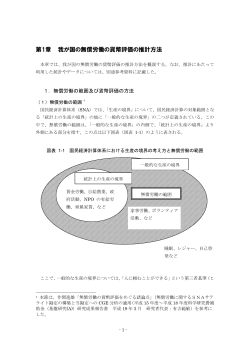
AY-141021 ILC SRF Industrializa2on Cost Sudy: ILC SRF 工業化コスト検討 Akira Yamamoto (KEK) 山本 明 LCC and KEK ILC Preparation Office LCC, KEK ILC 準備室 MEXT, ILC-TDR Validation Working Group 28th July, 2014, updated 20th Oct., 2014 A.Yamamoto, 2014/10/20 ILC-TDR, SCRF Cost Study 1 この報告の趣旨 • ILC TDR コスト見積もりの中から、最も関心が高く、 信頼性評価の核心となる、『超伝導加速空洞システ ム工業化コスト』について、その評価の為の作業、 経緯、結果を重点的に報告する。 – 詳しいコスト評価内容については、文科省・ILC-‐TDR 検証作業部会に 報告されている。 公式な『非公開情報』となり、慎重な取り扱いを、 文科省から求められている。 • また、このコスト見積もりの信頼性を高め、実現する 為には、なにが求められるかを、提言する。 A.Yamamoto, 2014/10/20 ILC-‐TDR, SCRF Cost Study 2 アウトライン • イントロダクション • 工業化への国際分担基本方針: • コスト評価作業のプロセス • コスト評価結果 • コスト評価結果・実現への道、提言 A.Yamamoto, 2014/10/20 ILC-‐TDR, SCRF Cost Study 3 ILC 加速器建設経費 (ILCUを日本円で換算) → 試算モデル ※ Premium (プレミアム:TDR 時点の見積不定性) Ø Value Premium: 26%, Labour Premium: 24% 日本円換算 プレミアム分 人件費 コスト(十億円) (十億円) (百万人時) TDRコスト(GDE作成) 日本で全て製造した場合 に相当 (PPP換算) 日本で予算執行(国際入札) した場合に相当ト(為替換算) @ 100 JYen/USD @ 115 JYen/Euro CFS SRF(本報告の焦点) A.Yamamoto, 2014/10/20 (8,300億円) (2,160億円) (1,598億円)(384億円) Notes; *TDR Cost:PPP indices used for TDR-‐Value to Convert to JYen (Jan. 2012) -‐ JY per USD: 127 (non-‐civil-‐construcPon) , 109 (civil-‐construcPon) -‐ JY per EU: 137 (non-‐civil-‐construcPon), 116 (Civil-‐construcPon) ILC-‐TDR, SCRF Cost Study 4 From TDR_Cost_ver4’-‐130605b/.pptx A2: ILC TDR Cost : Conversion to Japanese Yen using a model ※ Premium (Uncertainty in TDR value/labor es2mate, and to be prepared for unknown situa2on) 不定性として考えるべき範囲: コスト、人員、期間見積もり等の改訂に伴う Ø Value Premium ; 26% Ø Labour Premium; 24% TDR cost (by GDE) Cost based on PPP (full producPon in Japan) Cost base on exchange rate Using a model at 1USD=100Yen, 1Euro=115Yen (8,300億円) (1,598億円) (2,160億円) (384億円) Notes; *TDR Cost:PPP indices used for TDR-‐Value to Convert to JYen (Jan. 2012) -‐ JY per USD: 127 (non-‐civil-‐construcPon) , 109 (civil-‐construcPon) -‐ JY per EU: 137 (non-‐civil-‐construcPon), 116 (Civil-‐construcPon) 2014/10/18/AY ILC Project-‐Cost Overview 5 ILC Accelerator Cost Frac2on Dumps(and( Vacuum( Controls(and(Instrumenta0on( Collimators( 1%( 1%( Compu0ng( 1%( Infrastructrure( 6%( Magnets(and( Power(Supplies( 6%( Non(L$band(RF( 1%( Area(system( specific( 1%( CFS$Civil( construc0on( 18%( Installa0on( 1%( ILC Accelerator Cost for Asian Site: 7.98 BILC CFS: 29 % Civil: ~ 18 % Others: ~ 11% Cryogenics( 8%( CFS$other( 11%( SCRF 53 % Cavity & CM : ~ 35 % Cryogenics: ~ 8 % HLRF: ~ 10 % L$band(HLRF( 10%( L$band(Cavi0es( and( Cryomodules( 35%( A technical model for studying specially on industrializaPon/mass-‐producPon scale; -‐ Host Country: CFS ~ 100%, SCRF ~ 30 % à Total fracPon ~ 50 % A.Yamamoto, 2014/07/28 ILC-TDR, SCRF Cost Study 6 ILC-TDR Accelerator Parameters Parameters� Value� C.M. Energy� 500 GeV� Peak luminosity� Beam Rep. rate� Pulse duration� Average current � 1.5 x1034 cm-2s-1� 5 Hz� 0.73 ms� 5.8 mA (in pulse)� Av. field gradient� 31.5 MV/m +/-20% Q0 = 1E10� # 9-cell cavity� Beam&pipe Two"phase&He&& pipe LHe&tank HOM&coupler& & 16024 (x 1.1) # cryomodule 1,855� # Klystron� ~400� HOM&coupler& Frequency&tuner 9"cell&cavi*es Input&coupler& Construction Period for Cavity and CMs - Preparation + Full-production: ~ 6 years A.Yamamoto, 2014/10/20 ILC-TDR, SCRF Cost Study 7 Cavity/Cryomodule Fabrication 空洞・CMの製造 Purchasing Material/Sub-component Manufacturing Cavity:機械加工 Beam&pipe Two"phase&He&& pipe LHe&tank HOM&coupler& & Processing Surface:表面処理 Assembling LHe-Tank :組み立て HOM&coupler& Frequency&tuner 9"cell&cavi*es Input&coupler& Qualifying Cavity, 100 %:性能評価 Cavity String Assembly:多連空洞組立 Cryomodule Assembly:: CM 組立 Qualifying CMs, 33 + 5 %:CM性能評価 A.Yamamoto, 2014/10/20 ILC-TDR, SCRF Cost Study 8 SCRF Procurement/Manufacturing Model ILC Host-Lab Regional Hub-Lab: A ・市場は世界共通 ・企業は製造責任 ・研究所が性能責任 Regional Hub-Lab: B Regional hub-laboratories responsible to regional procurements to be open for any world-wide industry participation A.Yamamoto, 2014/10/20 Technical Coordination for Lab-Consortium World-wide Industry responsible to ‘Build-to-Print’ manufacturing Regional Hub-Lab: C: responsible to Hosting System Test and Gradient Performance ILC-TDR, SCRF Cost Study Regional Hub-Lab: E, & … Regional Hub-Lab: D : Technical coordination link : Procurement link 9 Progress in 1.3 GHz 9-cell Cavity Production year Capable Lab. Capable Industry 2006 1 DESY 2 ACCEL, ZANON 2011 4 DESY, JLAB, FNAL, KEK 4 RI, ZANON, AES, MHI, 2012 5 DESY, JLAB, FNAL, KEK, Cornell 5 RI, ZANON, AES, MHI, Hitachi -‐ One Lab (2 vendor) in 2006, and -‐ 5 Lab (5 vendor) in 2012 may handle it 2014/08/26, A. Yamamoto ILC 10 アウトライン • イントロダクション • 工業化への国際分担基本方針: • コスト評価作業のプロセス • コスト評価結果 • コスト評価結果・実現への道、提言 A.Yamamoto, 2014/10/20 ILC-‐TDR, SCRF Cost Study 11 SCRF R&D and Industrialization Study Year 07 2008 2009 2010 2011 2012 TDP-1 TDP-2 Cavity Gradient in v. test to reach 35 MV/m à Yield 50% à Yield 90% Cavity-string to reach 31.5 MV/m, with onecryomodule Global effort for string assembly and test Phase (DESY, FNAL, INFN, KEK) FLASH (DESY) , NML (FNAL)STF2 (KEK) System Test with beam acceleration Preparation for Industrialization 工業化準備 Communication with industry: 2009: 2010 -2011: 2011: 2011~2012: A.Yamamoto, 2014/10/20 Produc2on Technology R&D Visit Venders (2009) Organize Workshop (2010) Send specification & receive response Specific study w/ qualified companies in contracts ILC-TDR, SCRF Cost Study 12 工業化検討・コスト評価のプロセス 2008 技術開発à工業化プロセス基本方針の策定 ~ 2010 -‐ “Plug-‐CompaPbility” を基本とした国際分担 P.C.: LCWS-‐2008 (Chicago) 2009 企業訪問・意見交換・コスト検討(無償見積) ~ 2010 Hitachi, MHI, RI, Zanon, AES, Niowave, PAVAC 2010 国際会議でのIndustrializaPon Workshop(s)の ~ 2011 開催、企業との公開・意見交換 2010: IPAC-‐2010 2011: SRF-‐2011 2011 更なる企業訪問、意見交換 ~ 2012 工業化検討(契約)・コスト評価 訪問:19社 Cavity: RI, MHI, CM: BN, Hitachi QMag: Toshiba 2012 TDR and Cost EsPmate Document TDR へのコスト評価 2013 ~ Project 準備:工業化技術、最適化検討、検証 In progress A.Yamamoto, 2014/10/20 ILC-‐TDR, SCRF Cost Study 13 Plug-‐compa2ble Condi2ons Item� Varia2on� TDR Baseline� Cavity shape� TESLA / LL� TESLA � Length� Fixed� Beam pipe flange� Fixed� Suspension pitch� Fixed� Tuner� Blade/ Slide-‐Jack� Blade� Coupler flange (cold end)� 40 or 60� 40 mm� Coupler pitch� Fixed� He –in-‐line joint� Fixed� MagnePc shield� Inside/outside� Inside� Plug-‐compaPble interface established A.Yamamoto, 2014/10/20 ILC-‐TDR, SCRF Cost Study 14 Communication w/ Industry in 2009 - 2011 Visits to Industry in 2009 Twice Industrial Workshops: Industry invited 国際的工業界との2回に亘るワークショップ 意見交換を開催:2010~2011 A.Yamamoto, 2014/10/20 ILC-TDR, SCRF Cost Study 15 Communication with Industry, in 2009-2013 企業訪問・工業化検討協力 Year Company Place Technical subject 1 2009~2012 Hitachi Tokyo (JP) Cavity/Cryomodule (CM) 2 2009~2012 Toshiba Yokohama (JP) Cavity/CM, SC Quadrupole 3 2009~2012 MHI Kobe (JP) Cavity / CM 4 2011~2012 Tokyo Denkai Tokyo (JP) SC Material 5 2011 OTIC NingXia (CN) SC Material 6 2009 - 2011 Zanon Schio (IT) Cavity/CM 7 2009~2012 RI Koeln (DE) Cavity, Coupler 8 2009~2012 AES Medford, NY (US) Cavity 9 2009-2011 Niowave Lansing, MI (US) Cavity/CM 10 2009, 2012 PAVAC Richmond, BC (CA) Cavity 11 2011 ATI Wah-Chang Albany, OR (US) SC Material 12 2011 Plansee Ruette (AS) SC Material 13 2011 SDMS Sr. Romans (FR) Cavity 14 2011~2012 Heraeus Hanau (DE) SC Material 15 2011~2012 Babcock-Noell Wurzburg (DE) CM assembly 16 2011 SST Maisach (DE) EBW 17 2012 Toshiba Electron-Tube Nasu (JP) HLRF (Klystron, Coupler) 18 2012 Thales Velizy Villacoublay (FR) HLRF (Klystron) 19 2013 Wuxi City Creative Chemical Equip. (CX) Wuxi (CN) CM / Cryomodule components A.Yamamoto, 2014/10/20 ILC-TDR, SCRF Cost Study 16 共通の説明・技術仕様を示し、 コスト見積もりを依頼 A.Yamamoto, 2014/10/20 ILC-TDR, SCRF Cost Study 17 工業化における責任分担 • Industry: manufacture/vendor à 製造に責任 – Fabricate components based on “build to print” specificaPon: • Minimizing risk in industrial cost and maximizing cost-‐ effecPve mass producPon • Laboratory (Hub-‐laboratory) à “性能に責任” – Qualify components, such as caviPes, and cryomodules, • Requiring major test faciliPes – Responsible for the performance of the deliverables to the ILC host-‐laboratory A.Yamamoto, 2014/10/20 ILC-TDR, SCRF Cost Study 18 A Model for Cavity and CM Production and Qualification Process 空洞とクライオモジュール製造と性能評価 Step hosted Industry Industry/ Laboratory Hublaboratory ILC Hostlaboratory Regional constraint no yes or no yes yes Sub-comp/material - Production/Procurement Nb, Ti, specific comp. … Procurement 9-cell Cavity - Manufacturing 9-cell-cavity, Process, He-Jacketing Procurement 9-cell Cavity - Performance Test Cryomodule component - Manufacturing Cryomodule/Cavity - Assembly Cold, gradient test V. vessel, cold-mass ... Procurement Cav-string/ CM-assembly SCRF Cryomodule - Perofrmance Test Cold, gradient test Accelerator integration, Commissioning A.Yamamoto, 2014/10/20 Accelerator sys. Integ. ILC-TDR, SCRF Cost Study 19 研究所(自ら):製造・工業化技術開発に努力 EBW Press Trim SST EBOCAM KS-‐110 – G150KM Chamber (St. St. chamber) AMADA digital-‐survo-‐press SDE1522 150t, 50stroke/min, 225mmstroke MORI VKL-‐253 VerPcal CNC lathe Chemical process A.Yamamoto, 2014/10/20 ILC-‐TDR, SCRF Cost Study 20 KEK (in-house) 9-Cell Cavity (KEK-01) completed, and tested, April, 2014 36 MV/m A.Yamamoto, 2014/10/20 ILC-‐TDR, SCRF Cost Study 21 1.3 GHz 9-‐Cell Cavi2es/Resonators Solid high-grade niobium • RRR ≥300 1.3 GHz nine-cell niobium resonator (cavity) A High-power coupler port HOM coupler 2-phase He supply pipe Tank bellows Invar rod clamping pin Mechanical fabrication • deep drawing • electron-beam welding Surface preparation • electro-polishing • High-pressure rinsing • 800 deg C bake Following EXFEL cavity “biuld-‐to-‐print” SpecificaPon, as reference High-power coupler (cold part) Roller pad support 2K Li He tank B Tuner support rings Ultra-‐Clean Environment Required for assembly A.Yamamoto, 2014/10/20 N. Walker Cavity package: • HOM couplers (x2) • Magnetic shield • High-power input coupler • Ti-Nb Helium tank (cryostat) • Mechanical tuner ILC-‐TDR, SCRF Cost Study 22 Courtesy:W. Singer Reference for Cavity Specification 空洞の参考製造仕様(見積条件) • Technical guideline for ILC-GDE TDR and the cost estimate: – referring Specifications for EXFEL1.3 GHz Cavity, issued by DESY: acknowledged! • • • EXFEL/001 and associated documents :Rev.B, June 2009, by courtesy of W. Singer (DESY-XFEL)), The reference specification is available with ILC-GDE PMs, under permission of W. Singer (DESY-XFEL) URL: http://ilcagenda.linearcollider.org/event/ILC-SCRF-TR (scrf-treq) A.Yamamoto, 2014/10/20 ILC-TDR, SCRF Cost Study 数百ページに及ぶ詳細な 実計画入札の仕様を基準として 見積もり検討を依頼 23 Cavity and CM Industrial Studies: contracted in 2011-2012 (赤印:契約を伴う量産コスト検討) Company Mass production model Contract funded by Notes RI 100% à50% DESY Entirely new approach for mass production AES 20 % DOE/Fermilab Extension of current production model MHI 20, 50, 100% KEK Quadrupole Toshiba 100% à50 % KEK CM & assembly Hitachi 20, 50, 100% KEK AES 25% DOE/Fermilab BNG 100%à33 % CERN Cavity Entirely new approach Conduction cooled magnet Entirely new approach EXFEL experience kindly informed, in parallel, by DESY/INFN, CEA/Saclay A.Yamamoto, 2014/10/20 ILC-TDR, SCRF Cost Study 24 Study History and Our Proposal Tesla, ILC-RDR, TDR への検討経過 Regional/Global Tesla ILC-RDR ILC-TDR DESY centered effort Based on global contribution Based on global contribution Sub-components Rely on worldwide market Rely on world-wide Rely on world-wide market market 9-cell cavity mechanical fab. Single vendor (単企業) Single vendor (単企業) Two vendors assumed(複数企業) Cavity Tested at DESY performance test Tested at ILC host- Shared w/ hublab laboratories Cryomodule component To be understood Toe be understood Cryomodule assembly Single vendor or Single vendor or contract contract Cryomodule Tested at DESY performance test (1/3 test?) A.Yamamoto, 2014/10/20 Two vendors assumed Three vendors assumed Tested at ILC host- 1/3 of CMs to be lab (1/3 test) tested, and shared w/ hub-laboratories ILC-TDR, SCRF Cost Study 25 IPAC14: Courtesy: H. Weise SC Linac (~ 1 km) E-XFEL: under construction 800 Cavities under production (at RI, Zanon) , and assembled / Tested at CEA-Saclay, DESY 2014/08/26, A. Yamamoto ILC 26 IPAC14: Courtesy: H. Weise SC Linac (~ 1 km) EXFEL: 1/20 Scale Project on going, Industrialization being verified !! 2014/08/26, A. Yamamoto ILC 27 IPAC14: Courtesy: H. Weise SCRF Cavity Production 2014.6: # cavities produced > 300. Usable Gradient: ~ < 30 > MV/m 2014/08/26, A. Yamamoto ILC 28 IPAC14: Courtesy: N. Walker SCRF Cavity Production ILC TDR acceptance 40 XFEL usable gradient (FE limited) Count 30 Maximum field 20 10 XFEL industrial production following ILC baseline process 0 10 20 30 Gradient MVêm 40 50 2014.6: # cavities produced > 300. Usable Gradient: ~ < 30 > MV/m 2014/08/26, A. Yamamoto ILC 29 超伝導加速空洞・工業化コスト評価の推移 300%# RelaPve cost per cavity 250%# 200%# 150%# 100%# 50%# TDR: Vol. 3-‐II, 15.7.1 0%# 100# A.Yamamoto, 2014/10/20 Number of caviPes 1000# ILC-TDR, SCRF Cost Study 10000# 30 超伝導加速空洞・工業化コスト評価の推移 300%# 課題: 空洞周辺要素(Coupler, Tuner, H-‐Vessel, Mag. Shield 等)を含むと 企業間のコスト差が開く à TDR 後の取り組み課題 RelaPve cost per cavity 250%# 200%# 150%# 100%# 50%# TDR: Vol. 3-‐II, 15.7.1 0%# 100# A.Yamamoto, 2014/10/20 Number of caviPes 1000# ILC-TDR, SCRF Cost Study 10000# 31 アウトライン • イントロダクション • 工業化への国際分担基本方針: • コスト評価作業のプロセス • コスト評価結果 • コスト評価結果・実現への道、提言 A.Yamamoto, 2014/10/20 ILC-‐TDR, SCRF Cost Study 32 1.3 GHz 9-‐Cell Cavi2es/Resonators Solid high-‐grade niobium • RRR ≥300 1.3 GHz nine-cell niobium resonator (cavity) A High-power coupler port Mechanical fabricaPon • deep drawing • electron-‐beam welding HOM coupler 2-phase He supply pipe Tank bellows Invar rod clamping pin High-power coupler (cold part) Roller pad support 2K Li He tank B Tuner support rings A.Yamamoto, 2014/07/28 Surface preparaPon • electro-‐polishing • High-‐pressure rinsing • 800 deg C bake We need to look at these, now Cavity package: • HOM couplers (x2) • MagnePc shield • High-‐power input coupler • Ti-‐Nb Helium tank (cryostat) • Mechanical tuner ILC-‐TDR, SCRF Cost Study 33 今後の課題 • 周辺機器を含めた、Cavity IntegraPon のコスト評価が課題 – 空洞本体のと周辺機器の製造(加工)コストは同レベル。 – Cost EffecPve な設計が求められる。 • • • • • • • • Cavity IntegraPon 超伝導材料 空洞本体 : 空洞表面処理: カプラー: チューナー: He容器: 磁気シールド: A.Yamamoto, 2014/10/20 1.00 0.2x 0.1x 0.2x 0.2x 0.0x 0.0x 0.0x ILC-‐TDR, SCRF Cost Study 34 S1-Global hosted at KEK: Global cooperation to demonstrate SCRF system DESY, Sept. 2010 DESY, FNAL, Jan., 2010 FNAL & INFN, July, 2010 INFN and FNAL Feb. 2010 March, 2010 A.Yamamoto, 2014/07/28 DESY, May, 2010 ILC-‐TDR, SCRF Cost Study June, 2010 ~ 35 H.Hayano S1-‐Global Cavity Packages 利点: チューナ構造が単純 HE 容器が単純 エンド部が長くなる TESLA-ILC cavity Blade tuner TESLA-XFEL cavity Lever-arm tuner DESY cavity FNAL cavity TTF-III coupler TTF-III coupler 利点(チューナー): モーターを外に 引き出し どの設計も、ILC の要求を達成できることを相互に確認 TESLA-like KEK cavity TESLA-like KEK cavity Slide-jack tuner (center) Slide-jack tuner (end) KEK-type1 cavity 利点(カプラー): 低温部にベローズなし) STF-2 coupler ILC-‐TDR, SCRF Cost Study KEK-type2 cavity STF-2 coupler 36 Cavities, Tuners, Couplers in S1-G Cryomodule TESLA Cavity (DESY/FNAL) Tesla-like Cavity (KEK) Slide-Jack Tuner (KEK) Blade Tuner (INFN/FNAL) Saclay Tuner (DESY) TTF-III Coupler (DESY/FNAL/SLAC) A.Yamamoto, 2014/10/20 ILC-‐TDR, SCRF Cost Study STF-II Coupler (KEK) 37 Scope of the Industrial study to be further made How? • • AnalyPcal cost study, based on EXFEL CM assembly specificaPons and Work Break-‐down Structure (WBS) But including ILC specificiPes (see below) 相対コスト(現状): • Coupler: STF > TTF-‐III coupler (XFEL) • Tune/He-‐V: S-‐Jack >> Blade >> Lever (XFEL) • Mag. Shield: Inside > Outside (XFEL) A.Yamamoto, 2014/10/20 ILC-TDR, SCRF Cost Study 38 XFEL vs ILC Cryomodule Cryomodules 3.7 3.7.1 CRYOMODULES Overview The accelerating gradient in the ILC main linac is supplied by over 16,000 9-cell superconducting RF cavities. These cavities are grouped into approximately 1,700 12.7 m long cryomodules. Each cryomodule holds nine cavities, their supporting structure, thermal shields, associated cryogenic piping, and the insulating vacuum vessel. Every third cryomodule in the main linac contains a superconducting quadrupole/corrector/BPM package in place of the center cavity. Another 150 cryomodules are located in the e+ and e sources and RTML bunch compressors. Most of these are the standard linac configuration of 9 cavities or 8 cavities plus quad. A few have special configurations of cavities and quadrupoles. 3.7.2 Technical Description The cryomodule design is a modification of the type developed and used in the TESLA Test Facility (TTF) at DESY, with three separate vacuum envelopes. The ILC cryomodules contain either nine 9-cell cavities or eight cavities plus a quadrupole package, and have a uniform length of 12.652 m. The cavity spacing within this modified cryomodule is (6-1/4) 0 = 1.327 m. This facilitates powering the cavities in pairs via 3 db hybrids with reflection cancelation in an alternate distribution scheme that may allow the elimination of circulators. Present day accelerators with superconducting RF cavities typically have many separate cryogenic supply boxes and associated warm-to-cold transitions, which represent a significant fraction of the cost. The concept adopted for the ILC is to significantly reduce this number by having a single long continuous string of about 2.5km—called a cryogenic unit—which is connected to one cryogenic supply box at the beginning and one end box. Type 4 Cryomodule 2K HGRP 2.2K SUPPLY 5K SUPPLY 80K RETURN 8K RETURN 40K SUPPLY 2K 2-Phase COOL DOWN WARM UP A.Yamamoto, 2014/10/20 BEAM AXIS ILC-TDR, SCRF Cost Study FIGURE 3.7-1. Representative Cryomodule Cross-Section. ILC Reference Design Report III-165 39 Inter-Cavity Spacing ILC Type-IV 105 XFEL 82 105 105 A.Yamamoto, 2014/10/20 140 353 292 Reduction in inter-cavity spacing Bellows: = 108à82 “Long” cavity end = 140à105 108 = 61 mm = 26 mm = 35 mm ILC-TDR, SCRF Cost Study 40 LCLS-‐II Cavity: a Tuner Design Op2on to be inves2gated EXFEL, Tesla type Tunder Heliu m Vesse l Tune r • • LCLS Tuner design covering the beam pipe flanges, overcoming a constraint with a shorter beam pipe On the other hand, motor access-‐ ability need to be figured out A.Yamamoto, 2014/10/20 SNS: SRF Tuner access-‐ ability demonstrated 41 コストをコントロールする努力 • 空洞工業化技術の習熟 – 工業化技術習熟 – 周辺機器を含めた最適化 • Plug-‐CompaPbility の概念を堅持 – 性能を満たしつつ、コスト・エフェクティブな設計ができる。 – コストを保ちつつ、性能を向上することができる。 • 一つの可能性: – 空洞にILC cavity (short type) に適応するLever-‐Tuner を組み込む。 – クライオモジュールにアクセスフランジを設け保守を可能に。 – フランジ追加に対応するコス増を、輻射シールド5Kを節約するこ とで吸収する。 A.Yamamoto, 2014/10/20 ILC-‐TDR, SCRF Cost Study 42 ILC Project Cost Overview ILC 計画・コスト見積もり(作業中) • Overall project cost for 500 GeV: (500 GeV 加速器建設) – including preparaPon, construcPon, and operaPon, • 含む項目:準備、建設、運転、(アップブレード) – Values converted to JY (with a model: 1 USD= 100 JY, 1EU = 115 JY), – Human resource (labor cost) converted JY TBD (with a model: 9,000 ~ 5,000 JY per hour, and 1,700 working hours per year). • Global cost sharing shall be discussed based on the world-‐wide overall cost 国際的なプロジェクト総コスト見積もりをベースに国際分担を検討 • Concerning the preparaPon, (準備段階について) – Pre-‐preparaPon for 2 years before decision given be carried out by exisPng R&D budgets, (not included in the overall project cost) 判断前の予備的な準備段階は、現存の先端技術開発予算、人員で技術開発を継続する (プロジェクトコスト一覧には、含まない) – Officiall preparaPon for 4 years azer the decision be carried out with a new budget authorized for the ILC preparaPon , 公式な準備期間(建設にむけた判断後)には、新たなプロジェクト準備費想定し、一覧に含む (それまでの 技術開発予算・人員は、ILC プロジェクト費用の一部に組み変えられる) 2014/10/18/AY ILC Project-‐Cost Overview 43 ILC Project Overview: プロジェクト全体像 Years TDR baseline Scenario 1 -‐ 2 Pre-‐preparaPon for 2yrs (for technical effort conPnuity) 前段階・先端技術開発の継続(2年) 3 -‐ 6 PreparaPon (4 yrs) ILC 建設への準備段階(4年) 7 -‐ 15 ConstrucPon (9 yrs) 建設(9年) (12 -‐) (start installaPon) 組み込みの開始 (13 -‐) (start preparaPon for Commissioning and operaPon (to be studied) 運転にむけた準備の段階的立ち上げ (検討要) 16 -‐ Beam Commissioning start ビームコミッショニング 17 – (30) OperaPon at 250 ~ 500 GeV (550 GeV) 物理実験 8250 ~ 500 GeV (550 GeV) TBD Toward 1 TeV upgrade 1 TeV アップグレード 2014/10/18/AY ILC Project-‐Cost Overview 44 ILC Project-‐Cost Overview (at 500 GeV) (V-‐ 1410120 Value 108 JY Uncertainty (-‐/+) %, JY Human Resource P-‐hr (FTE) 108 JY Uncertainty (-‐/+) %, JY Value+HR 108 JY Range 108 JY See note Formal Prepara2on (4 years) Accelerator + CFS (for 4 yrs) TBD TBD TBD A1 Lab. Support. -‐ Land, Load, Lab ... TBD TBD TBD A1 Detectors TBD TBD TBD A1 Construc2on (9 years) Accelerator (Acc. Equipm. + CFS) (TDR values) Lab. Support -‐ Safety, CompuPng, etc Det. Constr (for 9 yrs) 8,309 26% (5,709+2602) (7.98 BILC) 2,160 TBD 22.9 M (13,471) TBD 1,598 24% 384 9,907 TBD 7,363 ~ A2 12,451 TBD A2 SiD: 315 (315 MILC) ILD: 451 (392 MILC) -‐-‐-‐ -‐-‐-‐ +127 (+/-‐48) -‐-‐-‐ -‐-‐-‐ (748) (1,400) 89 150 -‐-‐-‐ -‐-‐-‐ -‐-‐-‐ -‐-‐-‐ 315+89 = 404 451+150 = 601 404~531 (553~649) A2 Acc. + CFS OperaPon 390 (390 MILC) 40% 156 -‐-‐-‐ (850) 101 25% 25 491 TBD A3 Lab. Support TBD TBD TBD Det. OperaPon TBD TBD TBD Full Opera2on (per year) 2014/10/18/AY ILC Project-‐Cost Overview 45 まとめ • TDR 加速器コスト評価のまとめ: – 加速器(及び施設)建設 • 物件費 (~ 8,300) +労務費(~1,600) = ~ 9,900 億円+/-‐ ~ 25 % – 運転(+運営)経費、作業中 • 物件費 (390+/-‐ TBD)+労務費 (100 +/-‐ TBD) =490 億円 +/-‐ TBD • 加速器超伝導関連経費は、加速器経費の~2/3 を占めている。 – その他の経費はRDR での評価(主として、アメリカの研究所での評価)に大きな ずれがでた場合にも、その影響は、全体計画に対しては、x 1/3 の効果に抑制さ れる。 • さらに詳細な個々のコスト評価については、今後、更なる取り組みにご協力 を頂くべき方々に、別途ご報告する機会(非公開)を頂きたい。 – 文科省・ILC-‐TDR検証作業部会での座長決裁と同様に、情報の守秘について、お 約束を頂いたうえで、ご報告させて頂くことにご理解、ご協力をお願い致します。 A.Yamamoto, 2014/10/20 ILC-‐TDR, SCRF Cost Study 46 Appendix A.Yamamoto, 2014/10/20 ILC-‐TDR, SCRF Cost Study 47 SCRF Linac Technology Beam&pipe Two"phase&He&& pipe HOM&coupler& LHe&tank & HOM&coupler& Frequency&tuner 9"cell&cavi*es Input&coupler& 1.3 GHz Nb 9-‐cellCaviPes 16,024 Cryomodules 1,855 SC quadrupole pkg 10 MW MB Klystrons & modulators 673 436 * * site dependent Approximately 20 years of R&D worldwide à Mature technology, overall design and cost 2014/08/26, A. Yamamoto ILC 48 空洞部品の種類と点数 Number of parts of SC Cavity (to be EBW into 10 sub-parts) 総部品点数:56個 10組の部品製作に要するEBW=48ヶ所 電子ビーム溶接(EBW)で行う Total number of parts: 56 Number of EBW for 10 sub-parts: 48 EBW=Electron Beam Welding 10 sub-parts ショートエンドグループ 1組 (部品12個) EBW12ヶ所 HOM1 4個 ショートエンドセル 4個 ダンベル 8組 (部品32個) インプット カップラー ポート 2個 ビームパイプ 2個 EBW24ヶ所 × 8組 ロングエンドグループ 1組 (部品12個) ダンベル 4個 EBW12ヶ所 A.Yamamoto, 2014/10/20 ILC-TDR, SCRF Cost StudyHOM2 4個 ビームパイプ 2個 ピックアップポート 2個 49 ロングエンドセル 4個 Mechanical Fabrication Dumbbell Manufacture Short end group Long end group Deep drawing of half cells Deep drawing of short half cell Deep drawing of short half cell EB welding of 2 half cells + stiffening ring EB welding with beam tube, connecting flange and conical disk EB welding with beam tube, connecting flange and conical disk Manufacture and welding of HOM coupler parts Manufacture and welding of HOM coupler parts Port necking of beam tube for HOM & coupler tubes Port necking of beam tube for HOM tubes EBW of coupler and HOM port tubes to beam tube EBW of pick-up and HOM port tubes to beam tube Final EBW of end group Final EBW of end group EBW of 8 dumbbells + 2 end groups (9 equator welds) RF measurement of half-cell (determine trimming factor for equator) RF measurement of half-cell (determine trimming factor for equator) Helium leak cheak Turning of equator prior to EBW Turning of equator prior to EBW RF measurement of dumbbell (determine trimming factor for equator) Turning of equator prior to EBW stiffening ring dumbbell long end group Final Assembly Final dimensioning control short end group Final visual inspection EB WELDING Frequency control (bead-pull) MECHANICAL INSPECTION / A.Yamamoto, 2014/10/20 MEASUREMENT ILC-TDR, SCRF Cost Study 50 Standard Process Selected in Cavity Production and the Yield Standard Cavity Recipe Fabrication Nb-sheet (Fine Grain) Component preparation Cavity assembly w/ EBW (w/ experienced venders) Process 1st (Bulk) Electro-polishing (~150um) Ultrasonic degreasing with detergent, or ethanol rinse High-pressure pure-water rinsing Hydrogen degassing at > 600 C Field flatness tuning 2nd Electro-polishing (~20um) Ultrasonic degreasing or ethanol High-pressure pure-water rinsing Antenna Assembly Baking at 120 C Cold Test (vert. test) A.Yamamoto, 2014/10/20 Performance Test with temperature and mode measurement (1st / 2nd successful RF Test) ILC-TDR, SCRF Cost Study 51 Surface Preparation (XFEL) Bulk EP of inner-surface (110 micron) ISO 4 Clean Room BCP of outer surface (20 micron) • Key processes 30' HPR Ethanol rinse (sulphur removal) 800 deg C annealing (Hydrogen removal from bulk niobiuml) 120' HPR Frequency tuning, field flatness & eccentricity control Ethanol rinse (sulphur removal) – Electropolishing • 110µm, 40µm – – – – – – Final EP (40 micron) Leak check Helium tank assembly EBW of helium vessel ring and bellow section to conical disks on cavity TIG welding of helium tank 12 hour HPR Assembly of FMS (required for helium tank welding) Leak check and vent to argon gas Helium tank pressure test Helium tank leak test Disassembly of FMS Fiducialisation Assembly of pick-up, HOM coupler flange and high-Q antenna Dimensioning control (with tank) • ISO 4 clean room required Leak check of cavity 12 hour HPR Leak check / RGA of cavity (remains under vacuum after check) Ethanol rinse Baking (800° C,120° C) High pressure rinse (HPR) Frequency measurement Pressure testing / leak check Helium tank assembly 120 deg C bake (48 hours) cavity actively pumped – cavity passes 3× through clean room (XFEL spec.) RF measurement of fundamental mode and pass bands Packaging for transport to cold-test facility A.Yamamoto, 2014/10/20 ILC-TDR, SCRF Cost Study 52 Cavity/Cryomodule Fabrication 空洞・CM の製造プロセス Purchasing Material/Sub-component Manufacturing Cavity Beam&pipe Two"phase&He&& pipe LHe&tank HOM&coupler& & Processing Surface HOM&coupler& Frequency&tuner Assembling LHe-Tank 9"cell&cavi*es Input&coupler& Qualifying Cavity, 100 % Cavity String Assembly Cryomodule Assembly Qualifying CMs, 33 + 5 % A.Yamamoto, 2014/10/20 ILC-TDR, SCRF Cost Study 53
© Copyright 2026 Paperzz