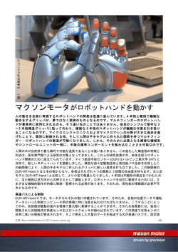
サーボモータ専用 For servo motor ABLE REDUCER VRXFSeries エイブル減速機選定ツール Servo Reducer Selection Tool STEP 1 ①取付モータから減速機を選定 ・ 画面中央にある 「減速機選定ツール」 のバナーをクリック 取付モータと減速機を選択する ・ Click the "Servo Reducer Selection tool" STEP 3 Make a selection from the motor list Select the motor and the reducer エイブル減速機 ・ 取付けるサーボモータメーカとモータ型式を選択します。 ・ 取付ける減速機のシリーズと減速比を選択します。 ABLE REDUCER ここでは、 カタログをダウンロードできます。 ・ 選択が終わったら、 ボタンをクリックします。 ・ Select the servo motor maker and model name ・ Select the reducer type and reduction ration * Here, you can download the catalogue ・ After making a selection click "Back" or "Next" STEP 2 下記の画面が立ち上がります。 ②負荷条件から減速機を選定 The screen below appears 選定方法は以下の 4 種類があります。 There are 4 ways to select the reducer ①取付モータから減速機を選定 ①Make a selection from the motor list ②負荷条件から減速機を選定 ②Make a selection from load condition ③アプリケーション検索 ③Application selection ④型式検索 NEW! ④Search reducer models NEW! STEP 3 減速機のシリーズを選択する。 Make a selection from load condition Select the reducer type ③アプリケーション検索 STEP 3 1 アプリケーションを選択する。 Application selection Select the application エイブル減速機を 4 種類の方法から簡単選定するよ! Select the Able reducers in 4 ways 注 ) EVRG および STH シリーズは掲載されておりません。 EVRG and STH series are not listed. 減速機サイズを選択する STEP 4 Select the reducer size はじめちゃん エイブル減速機 次ページへ to Next page ・ モータ型式によっては、 選択できるサイズとできないサイズがあります。 ・ 減速機サイズを選択して をクリックします。 STEP 4 負荷条件を入力する 次ページへ ABLE REDUCER ・ Depending on the motor model, certain sizes cannot be selected ・ Select the reducer size and click "Back" or "Next" to Next page 運転パターン数、 減速比、 ラジアル ・ 回転数 スラスト荷重、 荷重距離、 係数を入力します。 Input load condition input operaion cycle, reduction ration radial, rpm, thrust load, load distance, fomula 次ページへ STEP 5 STEP 4 減速機シリーズ、 減速比を選択する to Next page 必要に応じて荷重距離、 係数を入力します。 Select the reducer model and reduction ratio Input load distance and fomula if needed アプリケーションの運転条件を入力する Input operation cycle of the application 次ページへ to Next page STEP 3 ④型式検索 Search for the model number 2 エイブル減速機選定ツール Servo Reducer Selection Tool This is just one example of how to utilize our Servo Reducer Selection Tool We will keep making the improvment in its function of the Servo Reducer Selection Tool with the aim of making the best user friendly tool ①取付モータから減速機を選定 エイブル減速機 Make a selection from the motor list ②負荷条件から減速機を選定 Make a selection from load condition ③アプリケーション検索 Application selection ABLE REDUCER STEP 減速機サイズを選択する Select the reducer size モータメーカ、 型式を選択する Select the motor make and the model name 5 STEP 5 STEP 6 条件によっては選択できるサイズと 選択できないサイズがあります。 Depending on the condition, certain sizes cannot be chosen or can be chosen STEP 6 負荷条件出力可能なモータが選択できます。 The motor which can provide load condition can be selected ④型式検索 Search for the model number 外形寸法図、CADデータのダウンロード Download dimensions, CAD file 減速機の選定結果 The result of the reducer selection 選定 完了 Finish selection PDF、 DXF、 IGS、 STP の型式でダウンロードできます。 PDF, DXF, IGS, STP format data can be downloaded. 仕様表のダウンロード Download specification 減速機の選定結果には、 減速機型番、 減速機仕様、 取付モータ仕様が表示されます。 また、 仕様表、 外形 選定した型式について、 仕様表が ダウンロードできるようになりました。 ( 登録不要 ) The specification sheet of the selected reducer can be downloaded. (No registration required) 3 寸法図 (PDF、 2D、 3D) がダウンロードできます。 The result page shows the model number of the reducer and the specification of the reducer and the motor. The specification sheet, and dimension of the reducer (PDF, CAD drawing in DXF, IGS, and STP) can be downloaded from the same page. アプリケーション Applications ■ガントリーロボット Gantry robot ■自動箱詰め機 Auto packing sealing machine ■包装機(縦型ピロー) Packing machine (vertical pillow) ■包装機(横型ピロー) Packing machine (horizontal pillow) ■ディスペンサーロボット Dispenser robot ■ローダーロボット Loader robot ABLE REDUCER ■ベルトコンベア Conveyer-belt エイブル減速機 ■印刷機 Printer ■ターレットヘッド Turret head 実例いろいろ。様々な装置に 取付けられています。 Attachable and applicable to a range of applications and devices. 4 同芯軸 Coaxial shaft VRXF series 特徴 Features VRXF series エイブル減速機 ABLE REDUCER 5 VR 新設計の歯車と総コロ式構造により伝 達トルクアップ ※当社従来比 Superior torque transmission by the newly designed gear profile and the roller bearings. ※ compared with our current product 瞬時許容トルクは多くのサーボモータ に対応する定格の 350%まで対応(E 枠は 300%まで対応) Compatible with most servomotors' requirement with its peak allowable torque being up to 350% of the rated torque. (Up to 300% for E frame) 新しいはすば歯車の採用でさらに静音化 ※当社従来比 Further reduction of noise achieved with new helical gears. ※ compared with our current product 高性能グリースの採用でより高効率 ※ で漏油対策も万全 ※当社従来比 Higher efficiency ※ and leakage-free with high-performance grease. ※ compared with our current product 6,000rpm の高速入力にも対応 Capable to handle high input speed up to 6,000rpm. VRSFシリーズと取付寸法は同じで 互換が可能 Same dimension as our VRSF series and fully compatible and replaceable. 出力軸は、ご要望の多いストレート軸 ( キー溝レス ) を標準化 Straight shaft output (no key groove) is standard equipped, corresponding to customer feedback. ダイレクト結合方式とアダプタ・ブッ シュ結合方式のいずれかで世界中の サーボモータに取付可能 Works with all servomotors built anywhere in the world, either attached directly or with adapter/bushing system. IP65 相当(オプション) IP65 (optional) 防滴対応で、あらゆる環境下においても減速機の性能 をフルに発揮します。 ※オプションです Drip proof and fully utilizes the performance of the reducer under any environment. ※ Optional 種類 Kind 同芯軸 Coaxial shaft VRXF series ダイレクトタイプ Direct type 型式 Model VRXF - □ - 15C - S - 400 エイブル減速機 モータ容量が入る Motor Capacity ※詳細はP8参照 ※Refer to page 8, to more details 対応範囲 ・入力回転速度3000rpm時にて、モータ容量50W〜750W(サイズD枠まで) ・特定のモータメーカ、モータシリーズに対応 詳細は、選定ツールにてご確認ください。 ”Cover range” Motors ABLE REDUCER ・At Input speed 3000rpm, Motor capacity 50w~750w(Up to Frame D size) ・For certain motor maker, and series. As to the details, go to the "online selection". アダプタタイプ Adapter type 型式 Model VRXF - □ - 15C - S アダプタ、ブッシュコードが 入る adapter, Bush code ※詳細はP12参照 ※Refer to page 12, to more details 対応範囲 ・入力回転速度3000rpm時にて、モータ容量50W〜5000W ・国内、海外のモータメーカに対応 詳細は、選定ツールにてご確認ください。 ”Cover range” Motors ・At Input speed 3000rpm, Motor capacity 50w~5000w ・For various kinds of Motor Maker, and series. As to the details, go to the "online selection". <減速機の選定について> <Servo Reducer Selection> HPに掲載しております「減速機選定ツール」からも減速機を 選定していただけますので、ご活用ください。 The "online selector" tool on our website. HPアドレス http://www.nidec-shimpo.co.jp/ Website http://www.nidec-shimpo.co.jp/ VR 6 同芯軸 Coaxial shaft 減速比・枠番 VRXF series Reduction ratio/Frame size Input speed : 3,000rpm 減速比 Ratio 容量(W) Capacity 1 段減速 (Single) 1/3 1/5 1/9 1/15 1/20 1/25 1/35 1/45 1/81 B B B B B B B C C 50 エイブル減速機 ABLE REDUCER 100 B B B B B B C C D 200 B B C C C C C D E 400 B C C C C C D E 750 C C D D D D E E 1000 D D E E E E 1500 D D E E E 2000 D E E 2500 E E E 3000 E E E 3500 E E 4000 E E 4500 E 5000 E ※ダイレクトタイプは、 ※ Choose direct type from 7 VR 2 段減速 (Double) の範囲のみとなります (但し、 指定モータシリーズのみ) area (only for certain motor series) 機種・型式記号 Model number 同芯軸 Coaxial shaft VRXF series VRXF series (ダイレクトタイプ) VRXF series (Direct type) ABLE REDUCER 15 C S 400 Specify the motor manufacturer エイブル減速機 X F Servo motor Specify the motor model 型番 Model number メーカ名 Motor manufacturer 適応サーボモータ容量(W) Applicable servo motor capacity ABLE REDUCER 出力方式 S: 出力軸キー無し Output style Smooth shaft K: 出力軸キー付き(オプション) サイズ B、C、D Shaft with key (Optional) Frame size 減速比 1段 Single : 3、5、9 Ratio 2段 Double : 15、20、25、35、45、81 記号無し No Symbol : 標準 Standard PB : 高精度型 High-precision LB : ローバックラッシ型 Low-backlash バックラッシ Backlash specification ■バックラッシ※量 Backlash* 減速機サイズ Reducer frame size B frame C frame D frame 平均 (Standard) 15 arc-minutes (Low-Backlash) 10 arc-minutes (High-Precision) 3 arc-minutes 15 arc-minutes 5 arc-minutes 3 arc-minutes 15 arc-minutes 5 arc-minutes 3 arc-minutes % *Backlash value when the output shaft is subjected to +5% and -5% of the allowable average torque load. 取付け方式と出力軸方向 Output specification シリーズ名 Series name VRXシリーズ VRX Series エイブル減速機の呼称 Model name for ABLE reducer F : フランジ型 取付け方向自由 Flange Installation style is not limited D : Dフランジ付型 取付け方向自由 D-flange, output adapter Installation style is not limited 〔モータとの締付け方式について〕 ・ モータ軸は、キー溝なし ストレート軸での取付けとなります。 ・ モータ軸がキー溝付の場合は、キーを取外して取付けください。 ・ モータ軸がDカットの場合はお問い合わせください。 〔Mounting style to the motor〕 ・Motor output shaft is the smooth shaft without keyway. ・If the motor output shaft is with the keyway, remove the key from the shaft. ・If the motor output shaft has D shape cut, contact us. (オプション) Optional D-flange output adapter Unit サイズ D-flange Frame size ※As for the installation above, please purchase D-flange (option). D-flange is retrofittable. Output shaft tapping B枠 : M5 × 10 C枠 : M6 × 12 B frame: M5 × 10 C frame: M6 × 12 D枠 : M8 × 16 D frame: M8 × 16 VR 8 同芯軸 Coaxial shaft VRXF series 性能一覧(50W 〜 750W) Performance table (50W ~ 750W) VRXF series (ダイレクトタイプ) Same specification applies to all types, Standard, Low-backlash, High-precision. VRXF series (Direct type) Input speed : 3,000rpm エイブル減速機 型 式 Model number 減速比 Ratio ABLE REDUCER 1/3 1/5 1/9 1/15 1/20 1/25 1/35 1/45 1/81 出力 モータ 枠番 方式 容量 機種 減速比 Frame Output Motor Model Ratio number style capacity VRXF -3 B -□ -50 VRXF -3 B - □ -100 VRXF -3 B - □ -200 VRXF -3 B - □ -400 VRXF -3 C - □ -750 VRXF -5 B -□ -50 VRXF -5 B - □ -100 VRXF -5 B - □ -200 VRXF -5 C - □ -400 VRXF -5 C - □ -750 VRXF -9 B -□ -50 VRXF -9 B - □ -100 VRXF -9 C - □ -200 VRXF -9 C - □ -400 VRXF -9 D - □ -750 VRXF -15 B -□ -50 VRXF -15 B - □ -100 VRXF -15 C - □ -200 VRXF -15 C - □ -400 VRXF -15 D - □ -750 VRXF -20 B -□ -50 VRXF -20 B - □ -100 VRXF -20 C - □ -200 VRXF -20 C - □ -400 VRXF -20 D - □ -750 VRXF -25 B -□ -50 VRXF -25 B - □ -100 VRXF -25 C - □ -200 VRXF -25 C - □ -400 VRXF -25 D - □ -750 VRXF -35 B -□ -50 VRXF -35 C - □ -100 VRXF -35 C - □ -200 VRXF -35 D - □ -400 VRXF -45 C -□ -50 VRXF -45 C - □ -100 VRXF -45 D - □ -200 VRXF -81 C -□ -50 VRXF -81 D - □ -100 出力軸 回転速度 Output speed 許容平均 トルク Nominal output torque 許容最大 トルク Maximum output torque 許容 ラジアル荷重 Permitted radial load 許容 スラスト荷重 Permitted axial load 重量 Weight 慣性モーメント Moment of inertia [rpm] [Nm] [Nm] [N] [N] [kg] [kgcm2] 1000 1000 1000 1000 1000 600 600 600 600 600 333 333 333 333 333 200 200 200 200 200 150 150 150 150 150 120 120 120 120 120 85 85 85 85 66 66 66 37 37 4.46 4.46 4.46 4.46 8.92 3.69 3.69 3.69 15.0 15.0 3.06 3.06 12.6 12.6 23.7 5.23 5.23 21.1 21.1 39.5 6.50 6.50 27.4 27.4 52.8 8.15 8.15 34.3 34.3 65.9 4.99 20.2 20.2 48.1 12.4 12.4 36.8 12.6 23.1 12.0 12.0 12.0 12.0 24.0 9.94 9.94 9.94 40.3 40.3 8.23 8.23 34.0 34.0 63.7 14.1 14.1 56.7 56.7 106 17.5 17.5 73.9 73.9 142 21.9 21.9 92.4 92.4 177 13.4 54.3 54.3 130 33.3 33.3 99.1 34.0 62.3 392 392 392 392 784 490 490 490 980 980 588 588 1180 1180 1470 784 784 1470 1470 1760 804 804 1570 1570 1910 882 882 1670 1670 2060 882 1670 1670 2060 1670 1670 2060 1670 2060 196 196 196 196 392 245 245 245 490 490 294 294 588 588 735 392 392 735 735 882 402 402 785 785 955 441 441 833 833 1030 441 833 833 1030 833 833 1030 833 1030 0.55 0.55 0.72 0.71 2.1 0.55 0.55 0.72 1.7 2.1 0.55 0.55 1.7 1.7 3.4 0.7 0.7 2.1 2.1 3.8 0.7 0.7 2.1 2.1 3.8 0.7 0.7 2.1 2.1 3.8 0.7 2.0 2.1 3.8 2.0 2.0 3.8 2.0 3.6 0.0888 0.0888 0.175 0.175 1.02 0.0604 0.0604 0.147 0.370 0.817 0.0497 0.0497 0.273 0.273 0.755 0.0526 0.0526 0.302 0.302 0.685 0.0517 0.0517 0.296 0.296 0.664 0.0514 0.0514 0.293 0.293 0.658 0.0512 0.0853 0.291 0.328 0.0635 0.0635 0.275 0.0626 0.0682 ※ 1 表中の機種は、標準型、LB(ローバックラッシ)型、PB(高精度)型す べてに対応しています。 ※ 2 慣性モーメントは減速機(単体)入力軸換算の値を示します。 ※ 3 許容最高入力回転速度は 6,000rpm。許容平均入力回転速度は 3,000rpm となります。 ※ 4 許容ラジアル荷重は出力軸の軸中央部での値を示します。 ※ 5 許容スラスト荷重は出力軸芯に作用する時の値を示します。 9 VR ※ 1 Models in the table are available in all three types; Standard, LB (Low-backlash), PB (High-precision). ※ 2 The moment of inertia is that of the input shaft. ※ 3 Maximum input speed is 6,000rpm. Nominal input speed is 3,000rpm. ※ 4 The allowable radial load is measured at the center of the output shaft length. ※ 5 Permitted thrust load value is at the center of the output shaft. 寸法一覧(50W 〜 750W) Dimensions (50W ~ 750W) VRXF series (ダイレクトタイプ) 同芯軸 Coaxial shaft VRXF series VRXF series (Direct type) QK ST深Y ST depth Y ST深Y ST depth Y U W エイブル減速機 ) ) h6 h6 S( S( T QM キー無し キー付き 4-LZ深X 4-LZ depth X L LR □D Q LE ABLE REDUCER LA □F φLB(h7) φ ABLE reducer in-line shaft dimensions list Model number Overall length Output shaft Unit : Flange サイズ Frame size Ratio F Motor capacity ※ 出力軸回転方向はモータ入力回転と同方向になります。 ※ The output shaft rotates in the same direction as the motor. VR 10 同芯軸 Coaxial shaft VRXF series モータマッチング表 Motor matching table ڦ入力回転速度3,000rpm の時 モータメーカ Motormanufacturer パナソニック㈱ Panasonic エイブル減速機 ㈱安川電機 YaskawaElectric ABLE REDUCER 三菱電機㈱ MitsubishiElectric オムロン㈱ Omron 富士電機機器制御㈱ FujiElectric 山洋電気㈱ SanyoDenki Inputspeed : 3,000rpm モータ容量 (W) Motorcapacity(W) 100W 200W 400W TYPE1 TYPE1 アダプタタイプ 8AC8 TYPE1 Adaptertype TYPE3 TYPE3 TYPE2 TYPE3 TYPE3 TYPE3 TYPE3 TYPE3 TYPE3 TYPE3 TYPE3 TYPE3 TYPE3 TYPE3 TYPE3 TYPE1 モータシリーズ Motorseries MSME MSMD 50W MUMA SGMJV SGMAV SGMAS SGM7J SGM7A HF-KP HF-MP HF-KN HC-PQ HC-KQ HC-KFS HC-MFS HG-KR HG-MR R88M-K (200V) R88M-K (400V) TYPE3 R88M-G R88M-W R7M-A R7M-Z R88M-U GYS ※ TYPE3 TYPE1 TYPE2 TYPE2 - GYC アダプタタイプ 8BE8 Adaptertype TYPE3 - P30B Q1 MV ㈱三明 Sanmei ㈱日立産機システム HitachiIndustrialEquipmentSystems 三木プーリ㈱ MikiPulley アダプタタイプ 8AG8 Adaptertype アダプタタイプ 8AG8 Adaptertype アダプタタイプ 8AG8 Adaptertype VLBSV-ZA ※ TBL-i ※ TBL-iⅡ※ TBL-i Ⅳ TSM3102/3104/3202/ 3204/3304 TYPE3 TYPE3 TYPE3 TYPE3 - NA80 ※ NA70 ※ NA50 TS ※ SS ※ アダプタタイプ 14BK14 Adaptertype アダプタタイプ 19DC19 Adaptertype TYPE3 TYPE1 TYPE3 TYPE3 ADMA TYPE3 SA3 TYPE1 シンフォニアテクノロジー㈱ Sinfonia Technology Co., Ltd. - TYPE3 Note1 Mountingofoil-sealmotorsdifferentfromnon-oil-sealedmotorsin dimensioncanbesupportedbytheadapter.Fordetails,contactus. Note2 Contact us separately for motors with a D-cut motor shaft or taperedmotorshaft. Note3 Please note that generated thrust force may exceed the allowable servo motor thrust force at the instantaneous maximum output torque due to combination of the motor capacity (motor with ※ in thecorrespondencetable)andreductionratio. Note4 Motor of 1,000W or more can be supported by the adapter. For details,contactus. Note5 Thisisamatchingtableforaclamptighteningsystemonly. 上記以外にも下記サーボモータメーカ他、各社サーボモータシリーズへの取付対応も致します。 ホームページ上の選定ツールにて、マウントコードの確認ができます。 不明は場合は、お問い合わせください。 VR TYPE3 TYPE3 注 1オイルシール無しと寸法が異なる場合、オイルシール付モータ取付 はアダプタ対応となります。 注 2モータ軸が D カット、テーパタイプのものは別途お問い合わせくだ さい。 注 3モータ容量 (対応表※のモータ) と減速比の組み合せにより、瞬間 最大出力トルク時に発生スラスト力がサーボモータ許容スラスト力 をこえる場合がありますのでご注意ください。 注 41,000W 以上のモータは、アダプタ対応となります。 注 5クランプ締付け方式のみのマッチング表となります。 11 アダプタタイプ 19DB16 Adaptertype TYPE3 TBL-i Ⅳ TSM3201/3301/3302 日機電装㈱ NikkiDenso アダプタタイプ 19FA16 Adaptertype TYPE2 アダプタタイプ 19DB16 Adaptertype TYPE3 VLBST-Z 多摩川精機㈱ TamagawaSeiki TYPE2 TYPE2 TYPE2 アダプタタイプ 14DF14 Adaptertype TYPE3 VLBSV-Z ※ 東芝機械㈱ ToshibaMachine - アダプタタイプ 19FB19 Adaptertype TYPE1 SV ㈱キーエンス Keyence 750W VR reducers can attach to all brands of servo motors, including the following. Please contact our nearest sales branch or distributor. 日本電産サンキョー㈱ NIDEC Sankyo Corporation Allen-Bradley 他 Other 機種・型式記号 Model number 同芯軸 Coaxial shaft VRXF series VRXF series (アダプタタイプ) VRXF series (Adapter type) ABLE REDUCER 15 C S エイブル減速機 X F 19HB16 マウントコード(※1) Mount code(※1) ABLE REDUCER 出力方式 S: 出力軸キー無し Output style Smooth shaft K: 出力軸キー付き(オプション) サイズ B、C、D、E Shaft with key (Optional) Frame size 減速比 1段 Single : 3、5、9 Ratio 2段 Double : 15、20、25、35、45、81 バックラッシ 記号無し Backlash No Symbol : 標準 Standard specification PB : 高精度型 High-precision LB : ローバックラッシ型 Low-backlash ■バックラッシ※量 Backlash* 減速機サイズ Reducer frame size B frame C frame D frame (Standard) 15 arc-minutes (Low-Backlash) 10 arc-minutes (High-Precision) 3 arc-minutes 15 arc-minutes 5 arc-minutes 3 arc-minutes 15 arc-minutes 5 arc-minutes 3 arc-minutes 平均 % *Backlash value when the output shaft is subjected to +5% and -5% of the allowable average torque load. 取付け方式と出力軸方向 Output specification シリーズ名 Series name F : フランジ型 取付け方向自由 Flange Installation style is not limited VRXシリーズ VRX Series エイブル減速機の呼称 Model name for ABLE reducer アダプタタイプの特長 モータ取付け部品であるアダプタとブッシングを取替える だけで世界の様々なモータに取付けが可能になります。 ※1 マウントコード マウントコードは取付モータによって決まります。 ホームページ上の選定ツールにて確認できます。 不明な場合はお問い合わせください。 Shimpo’s adapter flange motor mounting methodology allows for nearly limitless motor mounting options. 〔モータとの締付け方式について〕 ・ モータ軸は、キー溝なし ストレート軸での取付けとなります。 ・ モータ軸がキー溝付の場合は、キーを取外して取付けください。 ・ モータ軸がDカットの場合はお問い合わせください。 ブッシング ※1 Mount code アダプタ Mount code varies depending on the motor. Please refer to reducer selection tool or contact us for more information. 〔Mounting style to the motor〕 ・Motor output shaft is the smooth shaft without keyway. ・If the motor output shaft is with the keyway, remove the key from the shaft. ・If the motor output shaft has D shape cut, contact us. Bushing Adapter ※アダプタ、ブッシングの仕組みを説明したイラストです。 外観が異なる場合があります。 ■選定ツール(日本語) (http://www.nidec-shimpo.co.jp/selection/jpn/) ■Selection tool (English) (http://www.nidec-shimpo.co.jp/selection/eng/) Output shaft tapping B枠 : M5 × 10 B frame: M5 × 10 C枠 : M6 × 12 C frame: M6 × 12 D枠 : M8 × 16 D frame: M8 × 16 E枠 : M10 × 20 E frame: M10 × 20 VR 12 同芯軸 Coaxial shaft VRXF series 性能一覧 Performance table VRXF series (アダプタタイプ) VRXF series (Adapter type) VRXF-□-□B Input speed : 3,000rpm エイブル減速機 枠番 Frame number Ratio 許容平均 トルク 許容最大 トルク 許容平均 入力回転速度 許容最高 入力回転速度 Nominal output torque Maximum output torque Nominal input speed Maximum input speed 4.46 3.69 3.06 5.23 6.50 8.15 4.99 12.0 9.94 8.23 14.1 17.5 21.9 13.4 3000 3000 3000 3000 3000 3000 3000 6000 6000 6000 6000 6000 6000 6000 ABLE REDUCER ※3 ※4 重量[kg] 慣性モーメント[kgcm2] Weight Moment of inertia 入力軸内径 入力軸内径 枠番 Frame number Ratio Input Bore ※1 ※2 Permitted radial load Permitted axial load ※1 ※2 Permitted radial load Permitted axial load Input Bore (≦φ8) (≦φ14) 0.65 0.75 0.87 0.95 (≦φ8) 0.089 0.060 0.050 0.057 0.056 0.055 0.055 (≦φ14) 0.18 0.15 0.14 0.14 0.14 0.14 0.14 VRXF-□-□C Input speed : 3,000rpm 枠番 Frame number Ratio 許容平均 トルク 許容最大 トルク 許容平均 入力回転速度 許容最高 入力回転速度 Nominal output torque Maximum output torque Nominal input speed Maximum input speed 8.92 15.0 12.6 21.1 27.4 34.3 20.2 12.4 12.6 24.0 40.3 34.0 56.7 73.9 92.4 54.3 33.3 34.0 3000 3000 3000 3000 3000 3000 3000 3000 3000 6000 6000 6000 6000 6000 6000 6000 6000 6000 枠番 Frame number Ratio ※3 ※4 重量[kg] 慣性モーメント[kgcm2] Weight Moment of inertia 入力軸内径 入力軸内径 Input Bore Input Bore (≦φ8) (≦φ14) (≦φ19) − 1.9 2.2 2.1 2.3 − ※1 許容ラジアル荷重は出力軸中央に作用する時の値を示します。 ※2 許容スラスト荷重は出力軸芯に作用する時の値を示します。 ※3 重量は減速比および入力軸寸法により若干異なります。 ※4 慣性モーメントは減速機(単体)入力軸換算の値を示します。 13 VR (≦φ8) − − − 0.145 0.140 0.137 0.135 0.113 0.112 (≦φ14) 0.57 0.37 0.27 0.30 0.30 0.29 0.29 0.27 0.27 (≦φ19) 1.0 0.82 0.74 − − − − − − ※1 Permitted radial load is measured at the middle of the output shaft. ※2 Permitted thrust load is measured at the center of the output shaft. ※3 The weight varies slightly depending on the input bore size and reduction ratio. ※4 The moment of inertia is reflected to the input shaft of the reducer. 性能一覧 Performance table VRXF series (アダプタタイプ) 同芯軸 Coaxial shaft VRXF series VRXF series (Adapter type) VRXF-□-□D Input speed : 3,000rpm Frame number Ratio 許容最大 トルク 許容平均 入力回転速度 許容最高 入力回転速度 Nominal output torque Maximum output torque Nominal input speed Maximum input speed 23.8 30.6 23.7 39.5 52.8 65.9 48.1 36.8 23.1 64.1 82.3 63.7 106 142 177 130 99.1 62.3 3000 3000 3000 3000 3000 3000 3000 3000 3000 6000 6000 6000 6000 6000 6000 6000 6000 6000 Ratio Permitted axial load ※3 ※4 重量[kg] 慣性モーメント[kgcm2] Weight Moment of inertia 入力軸内径 入力軸内径 枠番 Frame number Permitted radial load Input Bore ABLE REDUCER 許容平均 トルク ※2 エイブル減速機 枠番 ※1 Input Bore (≦φ8) (≦φ14) (≦φ19) (≦φ28) − 3.0 3.4 4.1 3.8 3.9 4.2 5.0 (≦φ8) − − − − − − − − 0.12 (≦φ14) 1.23 0.55 0.34 0.36 0.34 0.33 0.33 0.28 0.27 (≦φ19) 1.71 1.04 0.80 0.82 0.80 0.79 0.78 0.73 0.73 (≦φ28) 3.44 2.76 2.52 2.54 2.52 2.51 − − − VRXF-□-□E Input speed : 3,000rpm 枠番 Frame number Ratio 許容平均 トルク 許容最大 トルク 許容平均 入力回転速度 許容最高 入力回転速度 Nominal output torque Maximum output torque Nominal input speed Maximum input speed 57.3 73.8 95.6 119 102 85.0 92.3 119 56.3 132 171 221 274 235 196 213 274 130 3000 3000 3000 3000 3000 3000 3000 3000 3000 6000 6000 6000 6000 6000 6000 6000 6000 6000 Ratio ※2 Permitted radial load Permitted axial load ※3 ※4 重量[kg] 慣性モーメント[kgcm2] Weight Moment of inertia 入力軸内径 入力軸内径 枠番 Frame number ※1 Input Bore Input Bore (≦φ14) (≦φ19) (≦φ28) (≦φ38) − 6.3 7.1 9.4 7.3 7.7 8.4 10.8 ※1 許容ラジアル荷重は出力軸中央に作用する時の値を示します。 ※2 許容スラスト荷重は出力軸芯に作用する時の値を示します。 ※3 重量は減速比および入力軸寸法により若干異なります。 ※4 慣性モーメントは減速機(単体)入力軸換算の値を示します。 (≦φ14) − − − 0.65 0.58 0.56 0.54 0.36 0.35 (≦φ19) 4.0 1.8 1.0 1.1 1.0 1.0 0.99 0.81 0.80 (≦φ28) 5.8 3.6 2.7 2.8 2.8 2.7 2.7 2.5 2.5 (≦φ38) 13 11 10 11 10 10 − − − ※1 Permitted radial load is measured at the middle of the output shaft. ※2 Permitted thrust load is measured at the center of the output shaft. ※3 The weight varies slightly depending on the input bore size and reduction ratio. ※4 The moment of inertia is reflected to the input shaft of the reducer. VR 14 同芯軸 Coaxial shaft VRXF series 寸法一覧(本体) Dimensions(Main body) VRXF series (アダプタタイプ) VRXF series (Adapter type) QK U ST深Y ST depth Y ST深Y ST depth Y W エイブル減速機 ) 6) h6 S( h S( T QM キー無し キー付き ※3 4-LZ深X 4-LZ depth X L LR □D Q LE ABLE REDUCER LA φLB(h7) φE(G7) φ Dimensions 入力軸内径 Frame size Stage Input shaft bore E Single Double Single Double P16参照 Refer to page 16 P17参照 Refer to page 17 Single P18参照 Refer to page 18 Double Single P19参照 Refer to page 19 Double ※1 1段減速:1/3〜1/9、2段減速:1/15〜1/81(サイズBは1/15〜1/35) ※2 モータ軸径が入力軸径と異なる場合は、ブッシングが挿入されます。 ※3 取付けモータにより寸法が異なります。詳細は寸法一覧(アダプタ)を 参照ください。(P16〜P19参照) 15 VR ※1 Single reduction ratios include: 1/3 ~ 1/9, Double reduction ratios include: 1/15 ~ 1/81 (Frame Size B, 1/15 ~ 1/35). ※2 Bushings are available to accommodate motor shaft sizes not listed. ※3 These values may vary with the motor / adapter flange selected. For details, refer to the adapter flange dimensions list on pages 16-19. 寸法一覧(アダプタ) Dimensions(Adapter) VRXF series (アダプタタイプ) 同芯軸 Coaxial shaft VRXF series VRXF series (Adapter type) VRXF-□-□B エイブル減速機 ABLE REDUCER Single Model number AA・AC・AD・AF・AG・AL・AM・AN・AQ 99.5 VRXF 入力軸内径 Input shaft bore VRXF 入力軸内径 Input shaft bore Double **:Adapter code 104.5 BA・BB・BD・BE・BG・BH・BJ 99.5 104.5 104.5 BA・BB・BD・BE・BF・BG・BJ・BK・BP 104.5 BC・BH・BM・BN 109.5 114.5 CA・CC 104.5 109.5 DA・DB・DC・DD・DF・DH・DJ 104.5 DE・DL 109.5 DG・DK 114.5 EA・EB・EC・EF・EG・EK・EL 104.5 ED・EE・EH 114.5 EJ・EM 109.5 FA 104.5 FB 114.5 ※1 1 段減速 : 1/3〜1/9、2 段減速 : 1/15〜1/35 ※2 モータ軸径が入力軸径と異なる場合は、ブッシングが挿入されます。 ※3 アダプタは代表です。詳細については選定ツールでご確認ください。 67.5 □52 15.5 72.5 □52 20.5 67.5 □60 15.5 72.5 □60 20.5 72.5 □70 20.5 72.5 □65 16.5 77.5 □65 21.5 82.5 □65 26.5 72.5 □70 16.5 77.5 □70 21.5 72.5 □80 16.5 77.5 □80 21.5 82.5 □80 26.5 72.5 □90 16.5 82.5 □90 26.5 77.5 □90 21.5 72.5 □100 16.5 82.5 □100 26.5 32 37 32 37 37 35 40 45 35 40 35 40 45 35 45 40 35 45 115.5 120.5 115.5 120.5 120.5 118.5 123.5 128.5 118.5 123.5 118.5 123.5 128.5 118.5 128.5 123.5 118.5 128.5 83.5 □52 15.5 88.5 □52 20.5 83.5 □60 15.5 88.5 □60 20.5 88.5 □70 20.5 86.5 □65 16.5 91.5 □65 21.5 96.5 □65 26.5 86.5 □70 16.5 91.5 □70 21.5 86.5 □80 16.5 91.5 □80 21.5 96.5 □80 26.5 86.5 □90 16.5 96.5 □90 26.5 91.5 □90 21.5 86.5 □100 16.5 96.5 □100 26.5 32 37 32 37 37 35 40 45 35 40 35 40 45 35 45 40 35 45 ※1 Single reduction ratios include: 1/3 〜 1/9, Double reduction ratios include: 1/15 〜 1/35. ※2 Bushings are available to accommodate motor shaft sizes not listed. ※3 The adapter is only for example. Please select the suitable adapter in the selection tool in our web site. VR 16 同芯軸 Coaxial shaft VRXF series 寸法一覧(アダプタ) Dimensions(Adapter) VRXF series (アダプタタイプ) VRXF series (Adapter type) VRXF-□-□C エイブル減速機 ABLE REDUCER Single Model number VRXF 入力軸内径 Input shaft bore VRXF 入力軸内径 Input shaft bore VRXF 入力軸内径 Input shaft bore AA・AC・AD・AF・AG・AL・AM・AN・AQ AB・AE・AH・AJ・AK BA・BB・BD・BE・BG・BH・BJ BC・BF CA BA・BB・BD・BE・BF・BG・BJ・BK・BP BC・BH・BM・BN BL CA・CC CB DA・DB・DC・DD・DF・DH・DJ DE・DL DG・DK EA・EB・EC・EF・EG・EK・EL ED・EE・EH EJ・EM FA FB GA GB GC JA DA・DB・DC DD DE EA EB・ED EC FA FB GA・GC・GH GB・GD GE・GF HA HB HC・HD・HE JA JB 139.5 144.5 149.5 139.5 144.5 139.5 144.5 149.5 139.5 149.5 144.5 139.5 149.5 139.5 154.5 144.5 154.5 145.5 155.5 150.5 150.5 145.5 155.5 145.5 155.5 150.5 145.5 155.5 145.5 160.5 150.5 155.5 160.5 ※1 1 段減速 : 1/3〜1/9、2 段減速 : 1/15〜1/81 ※2 モータ軸径が入力軸径と異なる場合は、ブッシングが挿入されます。 ※3 アダプタは代表です。詳細については選定ツールでご確認ください。 17 VR Double **:Adapter code 89.5 94.5 99.5 89.5 94.5 89.5 94.5 99.5 89.5 99.5 94.5 89.5 99.5 89.5 104.5 94.5 104.5 95.5 105.5 100.5 100.5 95.5 105.5 95.5 105.5 100.5 95.5 105.5 95.5 110.5 100.5 105.5 110.5 □65 □65 □65 □70 □70 □80 □80 □80 □90 □90 □90 □100 □100 □115 □115 □115 □150 □80 □80 □80 □90 □90 □90 □100 □100 □115 □115 □115 □130 □130 □130 □150 □150 16.5 21.5 26.5 16.5 21.5 16.5 21.5 26.5 16.5 26.5 21.5 16.5 26.5 16.5 31.5 21.5 31.5 25 35 30 30 25 35 25 35 30 25 35 25 40 30 35 40 35 40 45 35 40 35 40 45 35 45 40 35 45 35 50 40 50 50 60 55 55 50 60 50 60 55 50 60 50 65 55 60 65 143.5 148.5 143.5 148.5 148.5 150 155 160 150 155 150 155 160 150 160 155 150 160 150 165 155 165 93.5 98.5 93.5 98.5 98.5 100 105 110 100 105 100 105 110 100 110 105 100 110 100 115 105 115 □52 □52 □60 □60 □70 □65 □65 □65 □70 □70 □80 □80 □80 □90 □90 □90 □100 □100 □115 □115 □115 □150 15.5 20.5 15.5 20.5 20.5 16.5 21.5 26.5 16.5 21.5 16.5 21.5 26.5 16.5 26.5 21.5 16.5 26.5 16.5 31.5 21.5 31.5 32 37 32 37 37 35 40 45 35 40 35 40 45 35 45 40 35 45 35 50 40 50 ※1 Single reduction ratios include: 1/3 〜 1/9, Double reduction ratios include: 1/15 〜 1/81. ※2 Bushings are available to accommodate motor shaft sizes not listed. ※3 The adapter is only for example. Please select the suitable adapter in the selection tool in our web site. 寸法一覧(アダプタ) Dimensions(Adapter) VRXF series (アダプタタイプ) 同芯軸 Coaxial shaft VRXF series VRXF series (Adapter type) VRXF-□-□D エイブル減速機 ABLE REDUCER Single Model number VRXF 入力軸内径 Input shaft bore VRXF 入力軸内径 Input shaft bore VRXF 入力軸内径 Input shaft bore VRXF 入力軸内径 Input shaft bore **:Adapter code AA・AC・AD・AF・AG・AL・AM・AN・AQ AB・AE・AH・AJ・AK BA・BB・BD・BE・BG・BH・BJ BC・BF CA BA・BB・BD・BE・BF・BG・BJ・BK・BP BC・BH・BM・BN BL CA・CC CB DA・DB・DC・DD・DF・DH・DJ DE・DL DG・DK EA・EB・EC・EF・EG・EK・EL ED・EE・EH EJ・EM FA FB GA GB GC JA DA・DB・DC DD DE EA EB・ED EC FA FB GA・GC・GH GB・GD GE・GF HA HB HC・HD・HE JA JB FA・FB・FC FD・FE GA・GB・GC・GD・GE・GF・GG・GH HA・HC・HD HB HE HF JA・JB・JC・JF JD JE KA・KB・KE KD 149 154 159 149 154 149 154 159 149 159 154 149 159 149 164 154 164 164 174 169 169 164 174 164 174 169 164 174 164 179 169 174 179 181 176 181 181 191 196 176 181 201 191 181 191 ※1 1 段減速 : 1/3〜1/9、2 段減速 : 1/15〜1/81 ※2 モータ軸径が入力軸径と異なる場合は、ブッシングが挿入されます。 ※3 アダプタは代表です。詳細については選定ツールでご確認ください。 88 93 98 88 93 88 93 98 88 98 93 88 98 88 103 93 103 103 113 108 108 103 113 103 113 108 103 113 103 118 108 113 118 120 115 120 120 130 135 115 120 140 130 120 130 □65 □65 □65 □70 □70 □80 □80 □80 □90 □90 □90 □100 □100 □115 □115 □115 □150 □80 □80 □80 □90 □90 □90 □100 □100 □115 □115 □115 □130 □130 □130 □150 □150 □100 □100 □115 □130 □130 □130 □130 □150 □150 □150 □180 □180 Double 16.5 21.5 26.5 16.5 21.5 16.5 21.5 26.5 16.5 21.5 26.5 16.5 26.5 16.5 31.5 21.5 31.5 25 35 30 30 25 35 25 35 30 25 35 25 40 30 35 40 35 30 35 35 45 50 30 35 55 45 35 45 35 40 45 35 40 35 40 45 35 40 45 35 45 35 50 40 50 50 60 55 55 50 60 50 60 55 50 60 50 65 55 60 65 67 62 67 67 77 82 62 67 87 77 67 77 163 168 163 168 168 165 170 175 165 170 165 170 175 165 175 170 165 175 165 180 170 180 178 188 183 183 178 188 178 188 183 178 188 178 193 183 188 193 195 190 195 195 205 210 190 195 215 205 195 205 102 107 102 107 107 104 109 114 104 109 104 109 114 104 114 109 104 114 104 119 109 119 117 127 122 122 117 127 117 127 122 117 127 117 132 122 127 132 134 129 134 134 144 149 129 134 154 144 134 144 □52 □52 □60 □60 □70 □65 □65 □65 □70 □70 □80 □80 □80 □90 □90 □90 □100 □100 □115 □115 □115 □150 □80 □80 □80 □90 □90 □90 □100 □100 □115 □115 □115 □130 □130 □130 □150 □150 □100 □100 □115 □130 □130 □130 □130 □150 □150 □150 □180 □180 15.5 20.5 15.5 20.5 20.5 16.5 21.5 26.5 16.5 21.5 16.5 21.5 26.5 16.5 21.5 26.5 16.5 26.5 16.5 31.5 21.5 31.5 25 35 30 30 25 35 25 35 30 25 35 25 40 30 35 40 35 30 35 35 45 50 30 35 55 45 35 45 32 37 32 37 37 35 40 45 35 40 35 40 45 35 40 45 35 45 35 50 40 50 50 60 55 55 50 60 50 60 55 50 60 50 65 55 60 65 67 62 67 67 77 82 62 67 87 77 67 77 ※1 Single reduction ratios include: 1/3 〜 1/9, Double reduction ratios include: 1/15 〜 1/81. ※2 Bushings are available to accommodate motor shaft sizes not listed. ※3 The adapter is only for example. Please select the suitable adapter in the selection tool in our web site. VR 18 同芯軸 Coaxial shaft VRXF series 寸法一覧(アダプタ) Dimensions(Adapter) VRXF series (アダプタタイプ) VRXF series (Adapter type) VRXF-□-□E エイブル減速機 ABLE REDUCER Single Model number VRXF 入力軸内径 Input shaft bore VRXF 入力軸内径 Input shaft bore VRXF 入力軸内径 Input shaft bore VRXF 入力軸内径 Input shaft bore BA・BB・BD・BE・BF・BG・BJ・BK・BP BC・BH・BM・BN BL CA・CC CB DA・DB・DC・DD・DF・DH・DJ DE・DL DG・DK EA・EB・EC・EF・EG・EK・EL ED・EE・EH EJ・EM FA FB GA GB GC JA DA・DB・DC DD DE EA EB・ED EC FA FB GA・GC・GH GB・GD GE・GF HA HB HC・HD・HE JA JB FA・FB・FC FD・FE GA・GB・GC・GD・GE・GF・GG・GH HA・HC・HD HB HE HF JA・JB・JC・JF JD JE KA・KB・KE KD HA HB・HE HC・HD JA KA・KB・KC KD KE LA LB MA・MB MC MD 198 208 203 203 198 208 198 208 203 198 208 198 213 203 208 213 211 206 211 211 221 226 206 211 231 221 211 221 226 221 231 226 226 261 241 226 236 226 241 236 ※1 1 段減速 : 1/3〜1/9、2 段減速 : 1/15〜1/81 ※2 モータ軸径が入力軸径と異なる場合は、ブッシングが挿入されます。 ※3 アダプタは代表です。詳細については選定ツールでご確認ください。 19 VR Double **:Adapter code 123 133 128 128 123 133 123 133 128 123 133 123 138 128 133 138 136 131 136 136 146 151 131 136 156 146 136 146 151 146 156 151 151 186 166 151 161 151 166 161 □80 □80 □80 □90 □90 □90 □100 □100 □115 □115 □115 □130 □130 □130 □150 □150 □100 □100 □115 □130 □130 □130 □130 □150 □150 □150 □180 □180 □130 □130 □130 □150 □180 □180 □180 □200 □200 □220 □220 □220 25 35 30 30 25 35 25 35 30 25 35 25 40 30 35 40 35 30 35 35 45 50 30 35 55 45 35 45 45 40 50 45 45 80 60 45 55 45 60 55 50 60 55 55 50 60 50 60 55 50 60 50 65 55 60 65 67 62 67 67 77 82 62 67 87 77 67 77 82 77 87 82 82 117 97 82 92 82 97 92 200 205 210 200 205 200 205 210 200 210 205 200 210 200 215 205 215 210 220 215 215 210 220 210 220 215 210 220 210 225 215 220 225 227 222 227 227 237 242 222 227 247 237 227 237 242 237 247 242 242 277 257 242 252 242 257 252 125 130 135 125 130 125 130 135 125 135 130 125 135 125 140 130 140 135 145 140 140 135 145 135 145 140 135 145 135 150 140 145 150 152 147 152 152 162 167 147 152 172 162 152 162 167 162 172 167 167 202 182 167 177 167 182 177 □65 □65 □65 □70 □70 □80 □80 □80 □90 □90 □90 □100 □100 □115 □115 □115 □150 □80 □80 □80 □90 □90 □90 □100 □100 □115 □115 □115 □130 □130 □130 □150 □150 □100 □100 □115 □130 □130 □130 □130 □150 □150 □150 □180 □180 □130 □130 □130 □150 □180 □180 □180 □200 □200 □220 □220 □220 16.5 21.5 26.5 16.5 21.5 16.5 21.5 26.5 16.5 26.5 21.5 16.5 26.5 16.5 31.5 21.5 31.5 25 35 30 30 25 35 25 35 30 25 35 25 40 30 35 40 35 30 35 35 45 50 30 35 55 45 35 45 45 40 50 45 45 80 60 45 55 45 60 55 35 40 45 35 40 35 40 45 35 45 40 35 45 35 50 40 50 50 60 55 55 50 60 50 60 55 50 60 50 65 55 60 65 67 62 67 67 77 82 62 67 87 77 67 77 82 77 87 82 82 117 97 82 92 82 97 92 ※1 Single reduction ratios include: 1/3 〜 1/9, Double reduction ratios include: 1/15 〜 1/81. ※2 Bushings are available to accommodate motor shaft sizes not listed. ※3 The adapter is only for example. Please select the suitable adapter in the selection tool in our web site. 同芯軸 Coaxial shaft 作動原理 VRXF series Operating principle Planetary gear A (Planetary gear B) * The explanation in ( ) shows the parts in second reduction. エイブル減速機 Internal gear A (Internal gear B) Input gear (Sun gear) * The explanation in ( ) shows the parts in second reduction. * The explanation in ( ) shows the parts in second reduction. ABLE REDUCER Planetary gear A Internal gear B Internal gear A Carrier Planetary gear B Output shaft Sun gear Input shaft Input Gear 1st stage reduction section Motor ∼ Input gear ∼ Planetary gear A ∼ Carrier Rotation from the motor is transmitted from the input gear mounted to the Input shaft. The input gear engages planetary gear A, which in turn engages internal gear A to produce an orbital motion to the planetary gears A. This rotates the 2nd stage carrier. 2nd stage reduction section B The direction of rotation at the output is the same as the direction of rotation at the input. Carrier ∼ Sun gear ∼ Planetary gear B ∼ Output shaft B B Rotation from the carrier is transmitted to the sun gear at the output of the carrier. The input gear engages planetary gear B, which engages the internal gear to produce an orbital motion to planetary gears B. The direction of rotation at the output is the same as the direction of rotation at the input. The explanation above describes how a double reduction (2 stage) reducer works. For explanation of how a single reduction (1 stage) reducer works, refer to the 2nd stage reduction section above. VR 20 同芯軸 Coaxial shaft 技術資料 VRXF series Technical data 型番選定 Selection of model No. エイブル減速機はモータ容量と減速比が決まれば、「減速比 ・ 枠番表」 から減速機の型式を簡単に選定することが出来ますが、標準外の組み 合わせをする場合や、詳細な計算が必要な場合には、以下に示す計算式から該当する減速機の型式を選定してください。 エイブル減速機 For ABLE REDUCER, once the motor capacity and reduction ratio are fixed, the reducer model can be simply selected according to the “Reductionratio&framesizetable.”However,inacasethatanon-standardcombinationismadeordetailedcalculationisnecessary,select theapplicablereducermodelaccordingtothecalculationsassuggestedbelow: ■負荷トルクパターンの確認 Checkup of load torque pattern 減速機に掛かる負荷トルクのパターンを確認します。 Checktheloadtorquepatterntobegiventothereducer. nOUT: 最高出力回転速度 Max.outputspeed (rpm)≧n1~nn nIN: 最高入力回転速度 Max.inputspeed (rpm)≧n1×R~nn×R R: 減速比 Reductionratio - 出力回転数 Output speed ABLE REDUCER ■各種記号の説明 Descriptionofsymbols T1~Tn(N ・ m) : 負荷トルク Loadtorque t1~tn(sec) : 時間 Time n1 ~nn(rpm) : 出力回転速度(加減速時は平均回転速度) Outputspeed(meanrotationalspeedatthetimeofacceleration &reduction) T1 T2 負荷トルク Load torque + T4 T3 t1 t2 t3 t4 n2 n1 n3 n4 ■型式選定手順 Model selection procedure 以下の手順に従って型式選定を行います。 Selectamodelaccordingtothefollowingprocedure: 1 負荷トルクパターンから、出力軸にかかる平均負荷トルクを算出します。 Calculate mean load torque given to the output shaft from the load torquepattern. 平均負荷トルク Meanloadtorque : Ta(N ・ m) 10/3 10/3 n 1t1│T1│ Ta = 10/3 + n2t2│T2│ 4 naIN = naOUT R ≦ 3,000 (rpm) 10/3 + … + nnt n│Tn│ 5 n1t1 + n2t2 +…+ nntn 負荷トルクパターンから、平均出力回転速度を算出します。 Calculatemeanoutputspeedfromtheloadtorquepattern. 平均出力回転速度 Meanoutputspeed : naOUT(rpm) naOUT = 2 n1t1 + n2t2 +…+ nntn t1 + t2 +…+ tn 平均出力回転速度 naOUT と減速比(R)から平均入力回転速度 naIN を算出します。 CalculatemeaninputspeednaINfrommeanoutputspeed naOUTandreductionratio(R). 最高入力回転速度が許容最高入力回転速度以下であることを 確認します。 Ensurethatmax.inputspeedislessthanorequaltothe fixedmax.inputspeed. nIN ≦ 6,000 (rpm) OK 次式の条件に当てはまるように、型式の仮選定をしてください。 Temporarilyselectamodeltomeetthefollowingequation. 6 T1、T3が性能表の許容最大トルクの値以内であることを確認 します。 EnsurethatT1andT3arewithinthevaluesofmax. instantaneousallowableoutputtorqueinthe performancetable. Ta ≦ 許容平均トルク Nominal output torque (各型式の許容平均トルクは性能表をご参照ください。) (Fornominaloutputtorqueofeachmodel,seethe performancetable.) 3 OK 最高出力回転速度(nOUT)と最高入力回転速度(nIN)から 減速比(R)を決定します。 Determinereductionratio(R)frommax.outputspeed(nOUT)andmax. inputspeed(nIN). nIN ≧R nOUT (nINはモータなどにより制限されます。) (nINislimitedbymotors,etc.) 最高出力回転速度(nOUT)と減速比(R)から最高入力回転速度(nIN)を 算出します。 Calculatemax.inputspeedfrommax.outputspeed(nOUT) andreductionratio(R). nIN = nOUT R 21 VR OK OK 型式の決定 Determination of model ※いずれか一つでも当てはまらない項目が有 る場合には、ひとつ上の型式で再検討する か、負荷トルクなどの条件の低減を検討して ください。 *Iftherearevaluesthatdonotfitwithin themaximum,examinethemodelagain,or considerconditionssuchasloadtorque. OK OK 技術資料 Technical data 同芯軸 Coaxial shaft VRXF series ■型式選定例 Examples of model selection 1 5 [運転パターン Operating pattern] 定常運転時 During normal operation : T2 = 35(Nm) t2 = 5(sec) n2 = 180(rpm) naIN = 62.7 × 25 = 1567.5 ≦ 3,000(rpm) 減速時 At deceleration : T3 = -70(Nm) t3 = 1(sec) n3 = 90(rpm) 停止時 While stopped : T4 = 0(Nm) t4 = 10(sec) n4 = 0(rpm) 6 [最高回転数 Max. number of rotations] 2 7 負荷トルクパターンから、出力軸にかかる平均負荷トルクを算出 します。 Calculate mean load torque given to the output shaft from the load torque pattern. 平均負荷トルク Mean load torque : Ta (N ・ m) 10/3 10/3 最高入力回転速度が許容最高入力回転速度以下であることを 確認します。 Ensure that max. input speed is less than or equal to the fixed max. input speed. nIN = 4,500 ≦ 6,000 (rpm) OK OK OK ABLE REDUCER 最高出力回転速度 Max. output speed : nOUT = 180(rpm) 最高入力回転速度 Max. input speed : nIN = 5000(rpm) (モータにより制限 limited by the motor) 平均出力回転速度 naOUT と減速比(R)から平均入力回転速度 naIN を算出します。 Calculate mean input speed naIN from mean output speed naOUT and reduction ratio (R). エイブル減速機 起動時 At acceleration : T1 = 90(Nm) t1 = 0.5(sec) n1 = 90(rpm) T1、T3 が性能表の許容最大トルクの値以内であることを 確認します。 Ensure that T1 and T3 are within the values of max. instantaneous allowable output torque in the performance table. T1 = 90 ≦ 177 (Nm) (Nm) T3 = 70 ≦ 177 OK 10/3 10/3 90×0.5×│90│ +180×5×│35│ +9 0×1×│- 70│ +0 Ta = 90 × 0.5 + 180 × 5 + 90 × 1+ 0 = 47.5(Nm) 負荷トルクパターンから、平均出力回転速度を算出します。 Calculate mean output speed from the load torque pattern. 平均出力回転速度 Mean output speed : naOUT(rpm) naOUT = 3 90 × 0.5 + 180 × 5 + 90 × 1+ 0 0.5 + 5 + 1 + 10 = 62.7(rpm) OK 型式の仮選定をします。 Temporarily select the model. VRXF-25D に決定 47.5 ≦ 65.9 (Nm) (性能表より VRXF-25D を選定) (Select VRXF-25D from the performance table) 4 OK Selected VRXF-25D 最高出力回転速度(nOUT)と最高入力回転速度(nIN)から 減速比(R)を決定します。 Determine reduction ratio (R) from max. output speed (nOUT) and max. input speed (nIN). 5000 = 27.8 ≧ 25 180 最高出力回転速度(nOUT)と減速比(R)から最高入力回転速度(nIN)を 算出します。 Calculate max. input speed (nIN) from max. output speed (nOUT) and reduction ratio (R). nIN = 180 × 25 = 4,500 (rpm) OK 減速機選定ツールを使用することで、上記のよ うな選定を簡単に行うことができます。 詳しくは P1 をご参照ください。 With the selection tool, proper reducer model can be easily selected. For detail, please refer to page 1. VR 22 ■このカタログは2016年1月現在の内容です。製品の外観・仕様などは改善のために変更することがあります。 ■Outside appearance and dimensions are subject to change without notice. This catalogue has been printed as of January 2016. 本社・営業本部 / 京都府長岡京市神足寺田1 〒617-0833 京 都(075)958-3608 FAX(075)958-3647 :1 Terada Kotari, Nagaokakyo-city, Kyoto, 617-0833 Japan Phone: 81-75-958-3608 FAX:81-75-958-3647
© Copyright 2026 Paperzz

![第29回 インターフェックス ジャパン [医薬品包装容器の漏れ試験機を展示]](http://s3.paperzz.com/store/data/005528224_1-6141df1ea683561e3718301bae21bd2a-250x500.png)