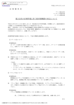
*
3
MASTER SETUP UNIT
MSU-900
MSU-950
付属の CD-ROM には、本機のオペレーションマニュアル ( 日本語、英語、フランス語、
ドイツ語、イタリア語、スペイン語 ) が PDF データ形式で入っています。詳しくは、
「CD-ROM マニュアルの使いかた」(6 ページ)をご覧ください。
The supplied CD-ROM includes Operation Manual (Japanese, English, French,
German, Italian, and Spanish versions) in PDF format. For details, see “Using
the CD-ROM Manual” on page 52.
電気製品は、安全のための注意事項を守らないと、火災や
人身事故になることがあります。
このオペレーションマニュアルには、事故を防ぐための重要な注意事項と
製品の取り扱いかたを示してあります。このオペレーションマニュアルを
よくお読みのうえ、製品を安全にお使いください。お読みになったあとは、
いつでも見られるところに必ず保管してください。
OPERATION MANUAL [Japanese/English]
1st Edition (Revised 5)
-
8
6
8
-
9
4
7
-
0
6
*
日本語
安全のために
ソニー製品は安全に充分配慮して設計されています。しかし、電気製品はまちがっ
た使い方をすると、火災や感電などにより死亡や大けがなど人身事故につながるこ
とがあり、危険です。
事故を防ぐために次のことを必ずお守りください。
安全のための注意事項を守る
警告表示の意味
オペレーションマニュアルおよび
製品では、次のような表示をして
います。表示の内容をよく理解し
てから本文をお読みください。
4 ∼ 5 ページの注意事項をよくお読みください。
定期点検を実施する
この表示の注意事項を守らないと、
長期間安全に使用していただくために、定期点検を実施することをおすすめしま
す。点検の内容や費用については、ソニーのサービス担当者または営業担当者にご
火災や感電などにより死亡や大け
がなど人身事故につながることが
相談ください。
あります。
故障したら使用を中止する
ソニーのサービス担当者、または営業担当者にご連絡ください。
この表示の注意事項を守らないと、
感電やその他の事故によりけがを
万一、異常が起きたら
したり周辺の物品に損害を与えた
りすることがあります。
異常な音、におい、煙が出たら
m
注意を促す記号
a 電源を切る。
b 電源コードや接続コードを抜く。
c ソニーのサービス担当者、または営業担当者に修理を依頼する。
炎が出たら
行為を禁止する記号
行為を指示する記号
m
すぐに電源を切り、消火する。
2
安全のために
目次
日
本
語
警告 .................................................................................................................................. 4
注意 .................................................................................................................................. 5
その他の安全上のご注意 ........................................................................................................ 5
CD-ROM マニュアルの使いかた ........................................................................................... 6
準備.............................................................................................................................. 6
オペレーションマニュアルを読むには........................................................................ 6
概要 ......................................................................................................................................... 7
主な特長 ...................................................................................................................... 7
各部の名称と働き ................................................................................................................... 8
操作パネル................................................................................................................... 8
コネクターパネル ...................................................................................................... 18
メニューの構成と基本操作................................................................................................... 20
基本操作手順 ............................................................................................................. 20
メニュー画面の基本構成 ........................................................................................... 21
メニュー項目 ............................................................................................................. 24
初期設定................................................................................................................................ 35
暗証番号の設定.......................................................................................................... 35
セキュリティステータスの設定 ................................................................................ 37
MSU-900/950 の動作環境の設定 ............................................................................... 39
“メモリースティック”について.......................................................................................... 47
仕様 ....................................................................................................................................... 48
目次
3
警告
電源コードを傷つけない
電源コードを傷つけると、火災や感電の
原因となります。
• 設置時に、製品と壁やラック、棚など
の間にはさみ込まない。
• 電源コードを加工したり、傷つけたり
しない。
• 重いものをのせたり、引っ張ったりし
ない。
• 熱器具に近づけたり、加熱したりしな
外装をはずさない、改造しな
い
外装をはずしたり、改造したりすると、
感電の原因となります。
内部の調整や設定および点検を行う必要
がある場合は、必ずサービストレーニン
グを受けた技術者にご依頼ください。
内部に水や異物を入れない
水や異物が入ると火災や感電の原因とな
ることがあります。
万一、水や異物が入ったときは、すぐに
電源を切り、電源コードや接続コードを
抜いて、ソニーのサービス担当者または
営業担当者にご相談ください。
油煙、湯気、ほこりの多い場
所では設置・使用しない
上記のような場所で設置・使用すると、
火災や感電の原因となります。
指定された電源コードを使用
する
指定以外の電源コードを使用すると、火
災や感電の原因となります。
4
警告
警告
い。
• 電源コードを抜くときは、必ずプラグ
を持って抜く。
万一、電源コードが傷んだら、ソニーの
サービス担当者に交換をご依頼ください。
注意
その他の安全上のご注意
注意
日本国内で使用する電源コードセットは、電気用品安全法で
定める基準を満足した承認品が要求されます。
ソニー推奨の電源コードセットをご使用ください。
メモリースティックスロット
に異物を入れない
指定のメモリースティック以外のものを
入れると、火災や感電の原因となること
があります。
電源コードのプラグおよびコ
ネクターは突き当たるまで差
し込む
まっすぐに突き当たるまで差し込まない
と、火災や感電の原因となります。
安全アースを接続する
安全アースを接続しないと、感電の原因
となることがあります。
次の方法でアースを接続してください。
・電源コンセントが 3 極の場合
指定の電源コードを使用することで安全
アースが接続されます。
・電源コンセントが 2 極の場合
指定の 3 極→ 2 極変換プラグを使用し、
変換プラグから出ている緑色のアース線
を建物に備えられているアース端子に接
続してください。
変換プラグ
アース線
安全アースを取り付けることができない
場合は、ソニーのサービス担当者または
営業担当者にご相談ください。
注意 / その他の安全上のご注意
注意
5
CD-ROM マニュアルの使
いかた
付属の CD-ROM には、MSU-900/950 のオペレーションマ
ニュアル(日本語、英語、フランス語、ドイツ語、イタリア
語、スペイン語)が PDF 形式で記録されています。
準備
付属の CD-ROM に収納されているオペレーションマニュア
ルをご覧いただくためには、以下のソフトウェアがコン
ピューターにインストールされている必要があります。
• Adobe Reader 6.0 以上
メモ
Adobe Reader がインストールされていない場合は、下記
URL よりダウンロードできます。
http://www.adobe.co.jp/products/acrobat/readstep2.html
Adobe および Adobe Reader は、Adobe Systems Incorporated(アドビシス
テムズ社)の商標です。
オペレーションマニュアルを読むには
CD-ROM に入っているオペレーションマニュアルを読むに
は、次のようにします。
1
CD-ROM を CD-ROM ドライブに入れる。
表紙ページが自動的にブラウザーで表示されます。
ブラウザーで自動的に表示されないときは、CD-ROM
に入っている index.htm ファイルをダブルクリックして
ください。
2
読みたいオペレーションマニュアルを選択してクリック
する。
オペレーションマニュアルの PDF ファイルが開きます。
メモ
Adobe Reader のバージョンによって、ファイルが正しく表
示されないことがあります。「準備」の項の URL より最新の
ソフトウェアをダウンロードしてお使いください。
6
CD-ROM マニュアルの使いかた
ご注意
CD-ROM が破損または紛失したため、新しい CD-ROM をご
希望の場合は、ソニーのサービス担当者にご依頼ください
(有料)。
19 インチのラックに取り付け可能
概要
マスターセットアップユニット MSU-900/950 は、ソニーの
BVP/HDC シリーズのスタジオ / 中継用 CCD カラービデオ
カメラの調整機能を、カメラコントロールユニット(CCU)
を介してリモートコントロールするためのコントロールパネ
19 インチの EIA 標準ラックに取り付け可能です。高さは、
MSU-900 が 5 ユニット、MSU-950 が 8 ユニットです。
MSU-950 は、RCP シリーズのリモートコントロールパネル
と並べてマウントすることができます。MSU-950 をラック
にマウントするには、取り付け金具が必要です。詳細につい
ては、ソニーのサービス担当者または営業担当者にご相談く
ださい。
ルです。
本機は、専用のケーブルで CCU または CCU に接続したカ
メラコマンドネットワークユニット(CNU)に接続するこ
とにより、CCU または CNU から最大 200 m 離して使用す
ることができます。
主な特長
カメラシステムを集中管理
CNU を使用することにより、1 台の MSU-900/950 から標準
で 12 台、最大で 24 台のカメラの調整が可能です。自照式ボ
タンの点灯や点滅、および各種インジケーターの表示によっ
て、システムの操作状況が把握できます。
誤操作した場合にカメラの動作やセットアップに重大な影響
を及ぼすボタンの周囲にはガードを付けるなど、様々な機能
を簡単かつ正確に操作できるようになっています。
タッチパネルにより各種機能に対応
操作ボタン、調整つまみによる設定項目に加え、様々な機能
をタッチパネルで選択・設定することができます。
ピクチャーモニター / 波形モニターコントロールが可能
映像モニターおよび調整用に、CCU に接続したピクチャー
モニターと波形モニターへの出力信号をコントロールするこ
とができます。各モニターへの信号は、パネル上のボタンで
簡単に切り換えられます。
“メモリースティック”スロット装備
シーンファイル、リファレンスファイルなど、各種データを
“メモリースティック”に保存し、必要なときに読み出して
再現することができます。
デジタル回線による接続
カメラコントロールユニットと本機との間は、デジタル回線
により信号の受け渡しを行います。1 本の接続ケーブル
(CCA-5)ですべての信号の送受信を確実に行うことができ
ます。
リモートコントロールパネルとの同時コントロールが可能
本機とリモートコントロールパネル RCP-700/900 シリーズ
との同時コントロールが可能です。
概要
7
各部の名称と働き
操作パネル
MSU-900
5 CLOSE ボタン
4 テスト信号出力選択ボタン
6 STANDARD ボタン
3 VF PW ボタン
7 AUTO SETUP 部
2 CAM PW ボタン
8 カメラ /CCU 機能 ON/OFF ボタン
1 ALL ボタン
9 メニュー操作部
MASTER SETUP UNIT MSU-900
MODE
AUTO SETUP
ALL
CAM PW
VF PW
TEST1
TEST2
BARS
KNEE
OFF
0“メモリースティック”
挿入部
qa シーンファイル操作部
SKIN DTL LEVEL START/
BREAK WHITE BLACK
CLOSE STANDARD AUTO HUE
KNEE
KNEE
APERTURE SAT
5600K
1
2
MONO COLOR
COLOR CORRECT
LOW KEY
SAT
AUTO
SKIN DETAIL SATURATION CONTRAST BLACK
GAMMA
KNEE DETAIL GATE
3
4
CHARACTER
MULTI
CONFIG
5
SCENE FILES
ON
FUNCTION
DETAIL LVLDEP GAMMA CHROMA MATRIX
OFF
OFF
OFF
OFF
OFF
MAINTENANCE
SCENE
STORE
FILE
SLS SHUTTER ECS
1
ECS/SHUTTER
R
G
GAMMA
B
ENC
PICTURE MONITOR
R
G
B
SEQ
MASTER GAIN
1
2
A
B
3
4
5
D
E
ND
FILTER CTRL
ENC
PAINT
WAVEFORM MONITOR
C
CC
EXT
IRIS/MB
ACTIVE
MULTI
PARA
AUTO
TALLY
CALL
PANEL
ACTIVE
EXPAND
1
2
3
4
5
6
7
8
9
10
11
12
13
14
15
16
17
18
19
20
21
22
23
24
qg カメラ選択部
MASTER BLACK
IRIS
wa アイリス調整部
w; カメラナンバー /
タリー表示部
qf WAVEFORM MONITOR ボタン
ql CALL ボタン
qd PICTURE MONITOR ボタン
qk MASTER BLACK 調整部
qs 制御部 / 表示部
qj IRIS/MB ACTIVE ボタン
qh フィルターコントロール部
8
各部の名称と働き
MSU-950
1 ALL ボタン
2 CAM PW ボタン
3 VF PW ボタン
4 テスト信号出力選択ボタン
5 CLOSE ボタン
6 STANDARD ボタン
7 AUTO SETUP 部
MASTER SETUP UNIT MSU-950
AUTO SETUP
ALL
8 カメラ /CCU 機能 ON/OFF ボタン
5600K
AM PW
AUTO
KNEE
qa シーンファイル操作部
VF PW
TEST1
TEST2
BAES
AUTO
KNEE
1
SKIN DTL LEVEL START/
BREAK
CLOSE STANDARD AUTO HUE
WHITE BLACK
CHARACTER
2
3
4
0“メモリースティック”挿入部
5
SCENE FILES
STORE
MODE
SCENE
FUNCTION
9 メニュー操作部
MULTI
CONFIG
MAINTENANCE
FILE
PAINT
qj IRIS/MB ACTIVE ボタン
qs 表示部
CALL
PANEL
ACTIVE
PARA
ECS/SHUTTER
EXPAND
GAMMA
MASTER
GAIN
ND
FILTER
ql CALL ボタン
w; カメラナンバー / タリー表示部
CC
IRIS/MB
ACTIVE
MULTI
TALLY
qg カメラ選択部
EXPAND
7
8
9
10
11
12
19
20
21
22
23
24
1
2
3
4
5
6
13
14
15
16
17
18
EXT
AUTO
MULTI
wa アイリス調整部
TALLY
EXPAND
MASTER BLACK
IRIS
qk MASTER BLACK 調整部
1 ALL(オールモード)ボタン
4 テスト信号出力選択ボタン
押して点滅させると、右の CAM PW から AUTO SETUP 部
までの 12 個のボタンの機能が、選択したグループのすべて
押して点灯させると、カメラのテスト信号発生器が作動し、
対応する信号が出力されます。
のカメラで有効になります。
TEST1(テスト 1):ビデオ回路チェック用のテスト信号
(ガンマ波形など)
2 CAM PW(カメラ電源)ボタン
TEST2(テスト 2):ビデオ回路チェック用のテスト信号
(階段波形など)
BARS(カラーバー):カラーバー信号
押して点灯させると、カメラに電源が供給されます。(ボタ
ンを押してから、カメラが立ち上がって通信可能になるまで
の間は、高速で点滅します。)
もう 1 度押すと点滅に変わり、カメラへの電源供給が遮断さ
れます。
3 VF PW(ビューファインダー電源)ボタン
押して点灯させると、カメラのビューファインダーに電源が
供給されます。
もう 1 度押して消灯させると、ビューファインダーへの電源
供給が遮断されます。
ご注意
BARS ボタンが点灯している場合は、BARS ボタンの機能が
優先されます。TEST1、TEST2 を選択するときは、BARS
ボタンを押して消灯させてください。
5 CLOSE(アイリスクローズ)ボタン
押して点灯させると、カメラの絞りがクローズします。もう
1 度押すとボタンは消灯し、クローズが解除されます。
各部の名称と働き
9
6 STANDARD(標準)ボタン
押すとカメラの各種設定が標準状態になり、ボタンが数秒間
点灯します。
ボタンが点灯している間にもう 1 度押すと、点灯する前の状
態に戻ります。
ご注意
自動調整中にエラーが発生した場合は、点灯させたボタンが
点滅します。
◆ 詳しくは、システムマニュアルをご覧ください。
8 カメラ /CCU 機能 ON/OFF ボタン
カメラや CCU の機能を、本機から ON/OFF することがで
7 AUTO SETUP(オートセットアップ)部
カメラの自動調整を行います。
きます。
工場出荷時は、MSU-900 は 19 個のボタンに、MSU-950 は 4
個のボタンに、それぞれ次のスイッチ機能が割り当てられて
います。MSU-900 では 8 個、MSU-950 では 4 個のボタンが
空きになっています。
a 自動調整項目選択ボタン
b START/BREAK ボタン
c WHITE ボタン
MSU-900
d BLACK ボタン
AUTO SETUP
SKIN DTL LEVEL START/
AUTO HUE
BREAK WHITE BLACK
KNEE
OFF
DETAIL LVL DEP GAMMA CHROMA MATRIX
OFF
OFF
OFF
OFF
OFF
KNEE
KNEE
APERTURE SAT
5600K
AUTO
KNEE
LOW KEY
SAT
MONO COLOR
COLOR CORRECT
SKIN DETAIL SATURATION CONTRAST BLACK
DETAIL GATE
GAMMA
CHARACTER
a 自動調整項目選択ボタン
押して点灯させ、自動調整する項目を選択します。
SKIN DTL AUTO HUE(スキンディテールオート
MSU-950 の場合は、次ページをご覧ください。
ヒュー):スキントーンディテールオートヒュー
LEVEL(レベル)
:ガンマバランス、ニーポイント、マス
・上段(ボタン点灯時が OFF)
ターブラックレベルなど
KNEE OFF(ニーオフ):ニー補償機能
DETAIL OFF(ディテールオフ):輪郭補正を行うディ
b START/BREAK(自動調整開始 / 中止)ボタン
テール機能
LVL DEP OFF(レベルディペンドオフ):暗部のディ
押すと、点灯している項目選択ボタンに対応する項目の自動
調整が実行されます。
テールを抑制するレベルディペンド機能
GAMMA OFF(ガンマオフ):ガンマ機能
調整中はボタンが点灯し、調整が完了すると消灯します。
自動調整実行中にこのボタンを押すと、自動調整が中止さ
CHROMA OFF(クロマオフ)
:クロマ機能
MATRIX OFF(マトリックスオフ)
:忠実な色再現を行う
れ、ボタンが点滅します。もう 1 度ボタンを押すと点滅が止
まります。
ためのリニアマトリックス機能
・中段(ボタン点灯時が ON)
c WHITE(ホワイトバランス自動調整)ボタン
KNEE APERTURE(ニーアパーチャー)
:ニーアパー
押すと、ホワイトバランスが自動調整されます。
調整中はボタンが点灯し、調整が完了すると消灯します。
チャー機能
KNEE SAT(ニーサチュレーション):ニーサチュレー
自動調整実行中にもう 1 度このボタンを押すか、START/
BREAK ボタンを押すと、自動調整が中止され、ボタンが点
滅します。もう 1 度ボタンを押すと点滅が止まります。
ション機能
LOW KEY SAT(ローキーサチュレーション)
:ローキー
サチュレーション(暗部のリニアマトリックス)機能
d BLACK(ブラックバランス自動調整)ボタン
を ON/OFF します。
MONO COLOR(モノカラー):輝度信号に単一色相のク
押すと、ブラックバランス、ブラックセットが自動調整され
ます。
調整中はボタンが点灯し、調整が完了すると消灯します。
自動調整実行中にもう 1 度このボタンを押すか、START/
BREAK ボタンを押すと、自動調整が中止され、ボタンが点
滅します。もう 1 度ボタンを押すと点滅が止まります。
10
各部の名称と働き
ロマ信号をミックスするためのモノカラー機能。ON
では、クロマレベルが輝度信号で変調されます。
COLOR CORRECT(カラー補正):特定色相範囲のカ
ラー補正機能
・下段(ボタン点灯時が ON)
5600K:5600K の電気色温度補正機能
AUTO KNEE(オートニー):オートニー機能。ON では、
ハイライトが入ると自動的にニーが働きます。
SKIN DETAIL(スキンディテール)
:肌色部分(顔など)
のディテールを抑制するスキントーンディテール機能
CHARACTER(文字情報)
:システム情報表示機能。
DETAIL GATE(ディテールゲート):スキントーンディ
テールゲート機能。ON では、スキントーンディテー
ルの調整範囲がモニター上に白く表示されます。
SATURATION(サチュレーション):サチュレーション
機能
CONTRAST(コントラスト)
:コントラスト機能
BLACK GAMMA(ブラックガンマ)
:ブラックガンマ機
能
CHARACTER(文字情報)
:システム情報表示機能。
CNU-700 の CHARACTER 端子に接続したモニター
に、システム全体の様々な情報を表示します。
MSU-950
5600K
AUTO
KNEE
SKIN
DETAIL
CHARACTER
5600K:5600K の電気色温度補正機能
AUTO KNEE(オートニー)
:オートニー機能。ON では、
ハイライトが入ると自動的にニーが働きます。
SKIN DETAIL(スキンディテール):肌色部分(顔など)
のディテールを抑制するスキントーンディテール機能
CHARACTER(文字情報):システム情報表示機能。
CNU-700 の CHARACTER 端子に接続したモニター
に、システム全体の様々な情報を表示します。
表示内容は、メニュー操作部で切り換えます。
表示内容は、メニュー操作部で切り換えます。
MSU-900 の場合
HD 機器使用時のカメラ /CCU 機能 ON/OFF ボタン
本機を HD カメラシステム(HDCU シリーズなど)で使
用するときは、さらに 2 つのカメラ /CCU 機能 ON/OFF
ボタンが有効になります。付属の HD 対応ラベルを所定
の位置に貼って使用してください。
KNEE
OFF
DETAIL LVL DEP GAMMA CHROMA MATRIX
OFF
OFF
OFF
OFF
OFF
KNEE
KNEE
APERTURE SAT
5600K
AUTO
KNEE
SD MATRIX SD DETAIL
OFF
OFF
LOW KEY
SAT
MONO COLOR
COLOR CORRECT
SKIN DETAIL SATURATION CONTRAST BLACK
DETAIL GATE
GAMMA
CHARACTER
・上段右 2 個のボタン(ボタン点灯時が OFF)
SD MATRIX OFF(SD マトリックスオフ)
:ダウンコ
ンバ−ト時のリニアマトリックスを ON/OFF しま
す。
SD DETAIL OFF(SD ディテールオフ):ダウンコン
バ−ト時の SD 輪郭補正機能を ON/OFF します。
各部の名称と働き
11
9 メニュー操作部
MSU-900
b LCD/ タッチパネル
MODE
FUNCTION
MULTI
CONFIG
a MODE ボタン
SCENE
MAINTENANCE
FILE
PAINT
c 調整つまみ
b LCD/ タッチパネル
MSU-950
MODE
SCENE
FUNCTION
a MODE ボタン
MULTI
CONFIG
MAINTENANCE
FILE
PAINT
c 調整つまみ
a MODE(モード選択)ボタン
12
SCENE(シーン):シーンファイル操作メニューを選択し
メニューのモードを選択します。
押して点灯させたボタンに対応するモードのメニューが
ます。カメラのシーンファイルの登録・読み出しを行い
ます。シーンファイル操作部でダイレクト操作が可能な
LCD に表示されます。
もう 1 度押してボタンを消灯させると、メニュー表示も消灯
します。
1 ∼ 5 以外の番号のシーンファイルは、このメニューで
操作します。
各部の名称と働き
FUNCTION(ファンクション)
:ファンクションメニュー
を選択します。カメラおよび CCU の各種機能の ON/
OFF や設定を行います。
MULTI(マルチ):マルチ制御メニューを選択します。
MSU-950
複数のカメラをコントロールするときのマスター / ス
レーブモードの設定などを行います。
CONFIG(コンフィギュレーション):コンフィギュレー
ションメニューを選択します。
b ACCESS インジケーター
本機およびシステム機器のコンフィギュレーション設定
を行います。
MAINTENANCE(メンテナンス)
:メンテナンスメニュー
を選択します。
CCU の H 位相、SC 位相などの設定やカメラの各種メン
テナンスを行います。
FILE(ファイル):ファイル操作メニューを選択します。
カメラや“メモリースティック”内の各種ファイル(リ
ファレンスファイル、レンズファイル、シーンファイル)
の呼び出し、登録、転送などの操作を行います。
PAINT(ペイント):ペイント調整メニューを選択します。
ホワイト、ブラック、フレアなどを調整します。
ご注意
ファンクションメニューとシーンファイル操作メニューは、
他のメニューへの割り込みメニューです。
◆ それぞれのメニューの項目については、
「メニュー項目」
(24
ページ)をご覧ください。
b LCD(液晶ディスプレイ)/ タッチパネル
MODE ボタンで選択したモードのメニューが表示され、各
種の設定を行います。
c 調整つまみ(ロータリーエンコーダー)
タッチパネルで選択した項目を調整します。
a“メモリースティック”スロット
a“メモリースティック”スロット
カメラや CCU のリファレンスファイル、レンズファイル、
シーンファイルを保存するための“メモリースティック”を
挿入します。
本機のバージョンアップ用のソフトウェアなどの読み込みも
行います。
“メモリースティック”の入れかた
“メモリースティック”のラベル側を手前にしてスロットに
差し込みます。
“メモリースティック”が正しくセットされると、ACCESS
インジケーターが緑に点灯します。インジケーターが点灯し
ない場合は、
“メモリースティック”の向きが逆になってい
る可能性があります。確認して正しく入れ直してください。
取り出すときは、
“メモリースティック”を押してください。
ご注意
ACCESS インジケーターが赤く点灯しているとき(データ
の読み出し / 書き込み中)は、
“メモリースティック”を取
り出さないでください。データが消えてしまうことがありま
す。
◆ 詳しくは、
「“メモリースティック”について」
(47 ページ)をご
覧ください。
0“メモリースティック”挿入部
b ACCESS(アクセス)インジケーター
“メモリースティック”の状態を表示します。
MSU-900
表示
意味 / 対応
消灯
“メモリースティック”が挿入されていません。
緑色に点灯
“メモリースティック”が挿入されています。
赤色に点灯
データの読み出し / 書き込み中です。この状態で
“メモリースティック”を抜き差しするとデータは保
b ACCESS インジケーター
a“メモリースティック”スロット
証されません。全データが消えてしまうこともあり
ます。
各部の名称と働き
13
qa シーンファイル操作部
qs 制御部 / 表示部
(MSU-950 の場合は表示部のみになります。15 ページをご覧
ください。
)
a シーンファイル番号表示部
b SCENE FILES ボタン
c STORE ボタン
MSU-900
a ON ボタン
b SLS/SHUTTER/ECS インジケーター
1
2
3
4
5
SCENE FILES
STORE
ON
SLS SHUTTER ECS
1
ECS/SHUTTER
a シーンファイル番号表示部
GAMMA
MASTER GAIN
f MASTER GAIN
ボタンと表示部
選択されているシーンファイルの番号(1 ∼ 32)が表示され
ます。1 ∼ 5 の場合は、対応する選択ボタンも同時に点灯し
e GAMMA ボタンと表示部
ます。
d ECS 周波数 / シャッタースピード /
SLS フレーム選択ボタンと表示部
b SCENE FILES(シーンファイル選択)ボタン
STORE ボタン点滅時:これらのボタンの 1 つを押して点灯
させると、その番号のファイルに現在の調整値が保存さ
れます。
a ON(オン)ボタン
STORE ボタン消灯時:これらのボタンの 1 つを押して点灯
させると、その番号のファイルが呼び出されます。もう
カメラの SLS 機能、シャッター機能または ECS 機能を ON/
OFF します。
1 度押してボタンを消灯させると、ファイル呼び出し前
の状態に戻ります。
c STORE(シーンファイル登録)ボタン
シーンファイル 1 ∼ 5 を登録するとき、このボタンを押して
点滅させてから、SCENE FILES ボタンでシーンファイルの
番号を選択します。ファイル登録が終了すると、このボタン
は消灯します。
登録を途中で中止するときは、SCENE FILES ボタンを押す
前に、もう 1 度このボタンを押して消灯させます。
c 分数インジケーター
押して点灯させると ON、もう 1 度押して消灯させると
OFF になります。
b SLS(スローシャッター)/SHUTTER(シャッター)/
ECS(拡張クリアスキャン)インジケーター
選択されている機能に対応するインジケーターが点灯しま
す。機能の選択はメニューで行ないます。
SLS:スローシャッターモード
SHUTTER:シャッターモード
ECS:ECS(拡張クリアスキャン:Extended Clear Scan)
モード
c 分数インジケーター
シャッター表示など、分数表示のとき点灯します。スロー
シャッター時は、設定値が 1S 以下のときに点灯します。
d ECS周波数/シャッタースピード/SLSフレーム選択ボタ
ンと表示部
ECS モード(ECS インジケーター点灯)時:表示部に
ECS 周波数が表示されます。周波数は、v(アップ)ボ
タンを押すたびに大きくなり、V(ダウン)ボタンを押
すたびに小さくなります。ボタンを押し続けると連続し
て変わります。
シャッターモード(SHUTTER インジケーター点灯)時:
分数インジケーターが点灯し、表示部にステップシャッ
ターのスピードの分母値が表示されます。シャッタース
ピードは、v(アップ)ボタンを押すたびに速くなり、
V(ダウン)ボタンを押すたびに遅くなります。ボタン
を押し続けると連続して変わります。
14
各部の名称と働き
スローシャッターモード(SLS インジケーター点灯)時:
表示部にフレームの蓄積数が表示されます。蓄積数は、
v(アップ)ボタンを押すたびに多くなり、V(ダウン)
ボタンを押すたびに少なくなります。ボタンを押し続け
d MASTER GAIN(マスターゲイン調整)表示部
カメラの利得(ゲイン)の設定値(単位 dB)が表示されま
す。
設定は、ファンクションメニューで行います。
ると連続して変わります。
e GAMMA(ガンマ選択)ボタンと表示部
e フィルター表示部
現在選択されている ND フィルターおよび CC フィルターが
ステップガンマを選択します。
設定値(小数値)が表示部に表示されます。
表示されます。
フィルターの選択は、ファンクションメニューで行います。
ガンマ値は、v(アップ)ボタンを押すたびに小さくなり、
V(ダウン)ボタンを押すたびに大きくなります。ボタンを
ND フィルター(例)
押し続けるとガンマ値が連続して変わります。
1:素通し
2:1/4 ND
ご注意
3:1/8 ND
4:1/16 ND
数値が小さいほどガンマの効きが大きくなります。
5:1/64 ND
f MASTER GAIN(マスターゲイン調整)ボタンと表示部
カメラの利得(ゲイン)を調整します。設定値(単位 dB)
が表示部に表示されます。
利得は、v(アップ)ボタンを押すたびに大きくなり、
V(ダウン)ボタンを押すたびに小さくなります。ボタンを
押し続けると連続して変わります。
MSU-950
CC フィルター(例)
A:クロスフィルター
B:3200K(素通し)
C:4300K
D:6300K
E:8000K
◆ ファンクションメニューについては、 22 ページ、33 ページを
ご覧ください。
b ECS 周波数 / シャッター
スピード / スローシャッ
ターフレーム表示部
c GAMMA(ガンマ選択)
表示部
d MASTER GAIN(マス
ターゲイン調整)表示部
a 分数インジ
ケーター
ECS/SHUTTER
e フィルター表示部
GAMMA
MASTER
GAIN
ND
FILTER
CC
a 分数インジケーター
シャッター表示など、分数表示のとき点灯します。スロー
qd PICTURE MONITOR(ピクチャーモニター選択)ボタン
(MSU-900 のみ)
CCU の PIX2 OUTPUT 端子からの出力信号を切り換えま
す。出力したい信号のボタンを押します。点灯しているボタ
ンに対応する信号が出力されます。
R/G/B:それぞれ R 信号、G 信号、B 信号を選択します。
単独、もしくは組み合わせて選択できます。エンコード
回路は OFF になります。
シャッター時は、設定値が 1S 以下のときに点灯します。
ENC(エンコード):R/G/B 回路が OFF になり、エンコー
ド信号が出力されます。
b ECS 周波数 / シャッタースピード / スローシャッターフ
qf WAVEFORM MONITOR(波形モニター選択)ボタン
レーム表示部
現在選択されている ECS 周波数またはステップシャッター
のスピード、スローシャッターフレームが表示されます。
モード(ECS モード(拡張クリアスキャン:Extended Clear
Scan)/ シャッターモード / スローシャッターモード)の切
り換えや、各設定(ECS 周波数、シャッタースピード、ス
ローシャッターフレーム)は、ファンクションメニューで行
います。
ECS/SHUTTER が OFF のときは「oFF」と表示されます。
c GAMMA(ガンマ選択)表示部
ステップガンマの設定値(小数値)が表示されます。
設定は、メニュー操作部のファンクションメニューで行います。
数値が小さいほどガンマの効きが大きくなります。
(MSU-900 のみ)
CCU の WF2 OUTPUT 端子の出力信号を切り換えます。出
力したい信号のボタンを押します。点灯しているボタンに対
応する信号が出力されます。
R/G/B:それぞれ R 信号、G 信号、B 信号を選択します。
単独、もしくは組み合わせて選択できます。シーケンス
回路、エンコード回路は OFF になります。
SEQ(シーケンス):R/G/B 回路、エンコード回路は OFF
になり、シーケンス信号が出力されます。波形モニター
で、R、G、B の 3 つの信号の波形を、シーケンシャル
モードでモニターすることができます。
ENC(エンコード):R/G/B 回路、シーケンス回路共に
OFF になり、エンコード信号が出力されます。
各部の名称と働き
15
qg カメラ選択部
MSU-900
a PARA ボタン
b PANEL ACTIVE ボタン
c MULTI インジケーター
d TALLY インジケーター
e アクティブインジケーター
MULTI
PARA
PANEL
ACTIVE
EXPAND
TALLY
1
2
3
4
5
6
7
8
9
10
11
12
f カメラ選択ボタン
13
14
15
16
17
18
19
20
21
22
23
24
g 拡張カメラ番号インジケーター
h EXPAND ボタン
MSU-950
a PARA ボタン
b PANEL ACTIVE ボタン
h EXPAND ボタン
PANEL
ACTIVE
PARA
EXPAND
7
8
9
10
11
12
c MULTI インジケーター
d TALLY インジケーター
e アクティブインジケーター
f カメラ選択ボタン
19
20
21
22
23
24
g 拡張カメラ番号インジケーター
1
2
3
4
5
6
13
14
15
16
17
18
MULTI
TALLY
EXPAND
MULTI
TALLY
EXPAND
a PARA(パラレルモード)ボタン
押して点灯させると、パラレルモードになり、他のパネル機
また、オートセットアップ中は赤く点灯します。オートセッ
トアップ中にエラー状態になってオートセットアップが中断
器との同時コントロールが可能になります。
もう 1 度押すと消灯し、パラレルモードが解除されます。
した場合は、赤く点滅します。
d TALLY(タリー)インジケーター
b PANEL ACTIVE(パネルアクティブ)ボタン
ボタンが消灯しているときに押すと点灯し、カメラ選択ボタ
それぞれ 1 ∼ 12 のカメラのタリーを表示します。EXPAND
ボタン点灯時は、13 ∼ 24 のカメラのタリーを表示します。
ンで選択したカメラを、本機からコントロールできる状態に
なります。このとき IRIS/MB ACTIVE ボタンも同時に点灯
対応するカメラに、レッドタリー信号が入力されると赤く点
灯し、グリーンタリー信号が入力されると緑に点灯します。
します。
もう 1 度押すと消灯し、本機のパネルがロックされます。
レッドタリー信号とグリーンタリー信号が同時に入力される
と、オレンジ色に点灯します。
c MULTI(マルチモード)インジケーター
それぞれ 1 ∼ 12 のカメラのモードに応じて点灯します。
16
また、コール信号が入力された場合は、赤く高速で点滅しま
す。
EXPAND ボタン点灯時は、13 ∼ 24 のカメラのモードに応
じて点灯します。
e アクティブインジケーター
それぞれ 1 ∼ 12 のカメラのコントロール状態に応じて点灯
対応するカメラが、マスター / スレーブモードでマスターに
なっていると緑に点灯し、スレーブになっているときはオレ
ンジ色に点灯します。
します。EXPAND ボタン点灯時は、13 ∼ 24 のカメラのコ
ントロール状態に応じて点灯します。
各部の名称と働き
本機にコントロール権があるカメラに対応するランプは緑に
例
点灯し、他のパネルにコントロール権があるカメラに対応す
るランプはオレンジ色に点灯します。
点灯していない場合は、対応するカメラ(カメラコントロー
1:素通し
2:1/4 ND
ルユニット)が接続されていないことを示します。
カメラや CCU で自己診断機能が働いてエラーが検出される
3:1/8 ND
4:1/16 ND
5:1/64 ND
と赤く点灯します。
f カメラ選択ボタン
FILTER CTRL ボタン消灯時は、カメラで選択されている
フィルターに対応するボタンが点灯します。
コントロールするカメラを選択します。押して点灯させたボ
タンの番号に対応するカメラを本機からコントロールするこ
c CC(色温度変換)フィルター選択ボタン
とができます。
EXPAND ボタン消灯時は 1 ∼ 12 のカメラを、点灯時は 13
FILTER CTRL ボタン点灯時に、希望のボタンを押して点灯
させると、対応する CC フィルターが選択されます。
∼ 24 のカメラを選択します。
例
g 拡張カメラ番号インジケーター
EXPAND ボタンを押したとき、13 ∼ 24 のカメラがカメラ
選択ボタン 1 ∼ 12 に対応するように点灯します。
h EXPAND(拡張)ボタン
カメラ選択ボタンで選択するカメラのグループを切り換えます。
消灯時は 1 ∼ 12 のカメラ、押して点灯させると 13 ∼ 24 の
カメラを選択できます。
ご注意
カメラ選択機能により複数台のカメラのコントロールを行う
には、カメラに応じたカメラコマンドネットワークユニット
A:クロスフィルター
B:3200K(素通し)
C:4300K
D:6300K
E:8000K
FILTER CTRL ボタン消灯時は、カメラで選択されている
フィルターに対応するボタンが点灯します。
qj IRIS/MB ACTIVE(アイリス / マスターブラックアク
ティブ)ボタン
押して点灯させると、本機でレンズの絞りとマスターブラッ
(CNU-700 など)が必要です。
クを調整できます。
PANEL ACTIVE ボタンを押して点灯させると、このボタン
qh フィルターコントロール部
も自動的に点灯します。本機からレンズの絞りとマスターブ
ラックを調整しないときは、ボタンを押して消灯させます。
(MSU-900 のみ)
qk MASTER BLACK(マスターブラック)調整部
つまみを回してマスターブラックを手動調整します。調整値
a FILTER CTRL ボタン
b ND フィルター選択ボタン
1
2
3
4
5
D
E
ND
FILTER CTRL
A
B
C
CC
c CC フィルター選択ボタン
が表示部に表示されます。
ql CALL(コール)ボタン
押すとカメラにコール信号が送出され、カメラ側の CALL
ボタンが点灯します。また、カメラのタリーランプと CCU
のレッドタリーランプは、それぞれ点灯していた場合は消灯
し、消灯していた場合は点灯します。
カメラ側で CALL ボタンが押されると、本機の CALL ボタ
ンが点灯し、ブザーが鳴ります。
w; カメラナンバー / タリー表示部
a FILTER CTRL(フィルターコントロール)ボタン
押して点灯させると、本機の ND ボタンまたは CC ボタンで
フィルターを選択できる状態になります。
本機でコントロールしているカメラのナンバーが、オレンジ
色で表示されます。
カメラにレッドタリー信号が入力されると、背景が赤く点灯
し、ナンバーは黒で表示されます。グリーンタリー信号が入
b ND フィルター選択ボタン
FILTER CTRL ボタン点灯時に、希望のボタンを押して点灯
力されると背景が緑に点灯し、ナンバーは黒で表示されます。
レッドタリー信号とグリーンタリー信号が同時に入力された
させると、対応する ND フィルターが選択されます。
場合は、背景の左半分が赤、右半分が緑に点灯します。
各部の名称と働き
17
d AUTO(自動絞り)ボタン
wa アイリス調整部
a EXT インジケーター
b D.EXT インジケーター
c IRIS つまみと表示部
d AUTO ボタン
押して点灯させると、レンズの絞りが入力光に応じて自動的
に調整されます(オートアイリス)
。
ボタン点灯時は、IRIS つまみで自動調整の基準値を± 2F の
範囲で微調整できます。
もう 1 度押すと消灯し、IRIS つまみによる絞りの手動調整
が可能になります。
ご注意
EXT
AUTO
スキントーンオートアイリス機能を持つカメラでスキントー
ンオートアイリス動作中に自動調整の基準となる被写体がな
くなると、その時点の絞り値を保持し、AUTO ボタンが点
滅します。
AUTO ボタンが点滅している状態では、オートアイリスが
動作しないだけでなく、手動で絞りを調整することもできま
せん。絞りを調整したいときは、ボタンを押してオートアイ
IRIS
リスを OFF にしてください。
オートアイリスを ON にし続けた場合は、再び基準被写体が
a EXT(レンズエクステンダー)インジケーター
レンズエクステンダーを使用しているとき点灯します。
写った時点で動作を再開します。
◆ スキントーンオートアイリスについては、システムマニュアルを
ご覧ください。
b D.EXT(デジタルエクステンダー)インジケーター
デジタルエクステンダーを使用しているとき点灯します。
c IRIS(アイリス調整)つまみと表示部
AUTO ボタン消灯時は、レンズの絞りを手動調整します。
調整値は F ナンバーで表示部に表示されます。
AUTO ボタン点灯時は、絞りの自動調整の基準値を微調整
(± 2F)します。
レンズをクローズすると表示部に「CL」が表示されます。
コネクターパネル
MSU-900
1 POWER スイッチ
2 AC IN 端子
3 CCU/CNU REMOTE 端子
4 AUX REMOTE 端子
REMOTE
AUX
CCU/CNU
POWER
I
-AC IN
I/O PORT
O
5 イーサネット端子
6 I/O PORT 端子
18
各部の名称と働き
MSU-950
3 CCU/CNU
REMOTE 端子
4 AUX
REMOTE 端子
1 POWER スイッチ
2 AC IN 端子
REMOTE
CCU/CNU
AUX
-AC IN
I/O PORT
5 イーサネット端子
6 I/O PORT 端子
1 POWER(電源)スイッチ
本機の電源を入 / 切します。
2 AC IN(AC 電源入力)端子
別売りの電源コードで AC 電源に接続します。別売りのプラ
グホルダーで電源コードを本機に固定することができます。
3 CCU/CNU REMOTE(カメラコントロールユニット /
カメラコマンドネットワークユニットリモート)端子
(8 ピン)
カメラコントロールユニットの RCP/CNU 端子やカメラコ
マンドネットワークユニットの MSU 端子に接続します。
4 AUX REMOTE(補助リモート)端子(8 ピン)
将来の拡張用です。
5 イーサネット端子
イーサネット接続時に使用します。
ネットワークケーブル(シールドタイプ、カテゴリー 5 以
上)を使用し、ネットワーク(10BASE-T/100BASE-TX)
のハブと接続します。
ご注意
安全のために、周辺機器を接続する際は、過大電圧を持つ可
能性があるコネクターをこの端子に接続しないでください。
接続については本書の指示に従ってください。
6 I/O PORT(I/O ポート)端子(50 ピン)
将来の拡張用です。
各部の名称と働き
19
FILE:ファイル操作メニュー(28 ページ)
メニューの構成と基本操作
PAINT:ペイントメニュー(28 ページ)
◆ 画面構成については 21 ページをご覧ください。
SCENE:シーンファイル操作メニュー(34 ページ)
MSU-900/950 では、メニュー操作により、システム機器の
調整など様々な機能に対応します。
◆ 操作については 23 ページをご覧ください。
2
操作する項目を選択する。
メニュー画面の項目ボタンを押し、設定・調整画面また
は操作エリアを表示させます。
基本操作手順
メニューが複数ページある場合は
MSU-900
ペイントメニューのようにメニューが複数ページある場
合は、v または V を押して、必要に応じてメニューの
2
MODE
FUNCTION
Clear
ページを切り換えます。
Home
◆「初期画面」
(21 ページ)参照。
MULTI
サブメニューがある場合は
CONFIG
1
SCENE
MAINTENANCE
ボタンを押して設定・調整画面を切り換えます。
FILE
◆「サブメニュー」(21 ページ)参照。
PAINT
3
3
MSU-950
項目を設定・調整する。
• 設定・調整項目(パラメーター)に対応するつまみを
回して(またはボタンを押して)、希望の値に調整
(希望の設定を選択)します。
2
◆「設定・調整画面」
(21 ページ)参照。
MODE
SCENE
Clear
Home
FUNCTION
1
MULTI
設定・調整が終わったら
CONFIG
• 引き続き同じメニューの別の項目を調整するときは、その
MAINTENANCE
項目のボタンを押します。
• 引き続き別のメニューの調整を行うときは、対応する
FILE
PAINT
3
1
メニューを表示させる。
MODE ボタンのいずれかを押して点灯させます。
メニュー操作モードになり、押した MODE ボタンに対
応するメニューがディスプレイに表示されます。それぞ
れのメニュー項目については、
( )内のページをご覧
ください。
FUNCTION:ファンクションメニュー(33 ページ)
◆ 画面構成については 22 ページをご覧ください。
MULTI:マルチ制御メニュー(24 ページ)
CONFIG:コンフィギュレーションメニュー(24 ページ)
MAINTENANCE:メンテナンスメニュー(26 ページ)
◆ 設定については「初期設定」
(35 ページ)をご覧くださ
い。
20
• メッセージが表示された場合は、メッセージに従って
操作し、 [OK] を押します。
メニューの構成と基本操作
MODE ボタンを押してメニューを切り換えます。
• メニュー操作モードを解除するときは、点灯している
MODE ボタンを押します。
• ファンクションメニューおよびシーンファイル操作メ
ニューは、現在設定しているメニューを解除しないで選択
することができます。
下記のいずれかの方法でファンクションメニューまたは
シーンファイル操作メニューを解除すると、そのメニュー
に切り換える前に表示されていた画面に戻ります。
- FUNCTION ボタンまたは SCENE ボタンを押して消灯
させる。
- 点灯している(直前に表示されていたメニューの)メ
ニュー選択ボタンを押す。
メニュー画面の基本構成
初期画面
例:ぺイントメニュー
設定値をクリアすることができます。
(設定・調整画面参照)
V Mod
Saw
Detail
Skin
Detail
Sat /
Contrast
Black
White
Flare
Gamma
/Knee
Home
押すと、メニューの 1 ページ目に戻り
ます。
1
4
いずれかを押して、メニューのページ
を切り換えます。
/
この画面で調整可能な項目(項目群)
の名称が表示されます。調整したい
項目(項目群)の部分を押すと、押
した部分の色が変わり、パネルの下
半分が調整画面になります。
Clear
ページ番号 / 総ページ数(1/4 は、ぺ
イントメニューが全部で 4 ページあ
り、現在 1 ページ目が表示されている
ことを意味します。
)
設定・調整画面
例:ガンマ / ニー調整画面(ぺイントメニューから
Gamma/Knee を選択したとき)
選択ボタン(色が変わる)
Home
Clear
Detail
Skin
Detail
Sat /
Contrast
Black
White
Flare
Gamma
/Knee
1
4
/
V Mod
Saw
選択した項目(項目群)名が表示され
ます。
Clear を押して赤色にした後に、この
部分を押すと、選択した項目(項目群)
の全調整値が標準状態 に戻ります。
調整に関連する ON/OFF 機能がある
場合は、この列に表示されます。
機能名を押すと、カメラ /CCU 機能
ON/OFF ボタンと同様に対応する機
能を ON/OFF することができます。
Gamma / Knee
Auto
Gamma
Black Knee Off
Knee
Off
Gamma
Gamma Blk Gamma Knee Point Knee Slope
-28
6
-21
10
選択した項目(項目群)の調整パラメーター(項目)および調整値が表示されます。
それぞれ対応する位置の調整つまみで調整することができます。
Clear を押して赤色にした後に数字部分を押すと、調整値が標準状態に戻ります。
サブメニュー
例:ディテールのサブメニュー(ペイントメニューから
Detail を選択したとき)
選択した項目群が複数のグ
ループに分かれている場合、
サブメニューが表示されます
(Detail 1 ∼ 3)。
希望のサブメニューを押して
切り換えます。
Detail 1
Detail
1
Level
3
Level
Detail
Detail
Detail
Dep Off
Off
2
3
Limiter
Crispening Level Dep
-7
Detail
Off
Detail 2
42
99
Detail
Detail
Detail
2
3
1
H/V Ratio Frequency Mix Ratio
0
0
0
Detail Comb
0
メニューの構成と基本操作
21
ファンクションメニュー画面
Operation 選択時
この画面の設定は、それぞれ対応する表示部(14 ページ)
に表示されます。
Exit
Operation
押して色を変えると、この画面でフィ
ルターを選択できる状態になります。
Ctrl
WF/PIX
Select
SW
ND
1
2
3
4
5
CC
A
B
C
D
E
Shutter
ECS
Shutter
ECS
Gamma
Master Gain
2000
30.0
0.45
0dB
それぞれ対応する位置の調整つまみ
で調整できます。
押すと、前に選択されていたメニュー
画面に戻ります。
[Ctrl] 選択時に、希望のボタンを押し
て色を変えると、対応するフィルター
が選択されます。 [Ctrl] 非選択時は、
カメラで選択されているフィルターに
対応するボタンの色が変わります。
それぞれ対応する位置の調整つまみを回すか、v/V を押して
設定できます。v を押すたびに値が大きくなり、V を押すた
びに小さくなります。押し続けると連続して変わります。
SW 選択時
Exit
22
メニューの構成と基本操作
SW
Satu
-ration
Contrast
Black
Gamma
WF/PIX
Select
Mono
Color
Color
Correct
Knee
Aperture
Knee
Sat
Skin
Detail
Detail
Gate
1
2
/
それぞれ対応する機能を ON/OFF しま
す。
Off の表示があるボタン(2 ペ−ジ目
の [Knee Off] など)は色が変わった
ときが OFF になり、それ以外のボタン
は色が変わったときが ON になります。
[5600K]、 [Auto Knee]、 [Skin
Detail] は、対応するカメラ /CCU 機能
ON/OFF ボタン(10 ページ)と連動
します。
Operation
5600K
Auto
Knee
押すと、前に選択されていたメニュー
画面に戻ります。
いずれかを押して、メニューのページ
を切り換えます。
ページ番号 / 総ページ数
(1/2 は、SW メニューが全部で 2 ページあり、現在
1 ページ目が表示されていることを意味します。
)
WF/PIX Select 選択時
Exit
Operation
WF/PIX
Select
SW
PIX
R
G
B
WF
R
G
B
押すと、前に選択されていたメニュー
画面に戻ります。
ENC
SEQ
希望のボタンを押して色を変えると、
対応するモニター出力が選択されます。
ENC
シーンファイル操作画面
シーンファイルの呼び出し :
呼び出したいシーンファイルの番号
を選択して押すと、登録されている
ファイルが呼び出されます。
このとき、呼び出されているシーン
ファイルの番号の色が変わります。
同じ番号を押すと、呼び出される前
の状態に戻ります。
b/B を押すと、ファイルが番号順に
切り換わります。
Scene Store/Recall
Exit
1
2
3
4
5
6
7
8
9
10
11
12
13
14
15
16
17
18
19
20
21
22
23
24
25
26
27
28
29
30
Scene #
31
32
Store
シーンファイルの登録 :
[Store] を押してから、希望のシーン
ファイル番号を選択します。
ファイル登録が終了すると、
[Store] の色が元に戻ります。
メニューの構成と基本操作
23
メニュー項目
操作 / 調整項目欄で●が付いている項目は調整つまみに割り
当てられる項目、それ以外の項目は、メニュー画面上で操作
ご注意
メニュー項目は、接続するカメラシステムやソフトのバー
する項目です。
ジョンにより異なります。
◆ 各機能の詳細については、接続されているカメラや CCU のオペ
レーションマニュアルをご覧ください。
マルチ制御メニュー(MULTI ボタンで選択)
メニュー
操作 / 調整項目
機能
Master/Slave
Master
マスター機の指定
Slave
スレーブ機の指定
All Slave
すべてのカメラをスレーブ機に指定
All Off
すべてのカメラのスレーブ指定を解除
Character on
CNU キャラクター出力 ON/OFF
Default
デフォルト表示選択
Character
System <#-#>
コントロールシステムの設定状態表示
Auto <#-#>
オートセットアップの内容表示
Diag <#-#>/One Cam
自己診断の結果表示
Data <#-#>/One Cam
カメラの設定状態の表示
コンフィギュレーションメニュー(CONFIG ボタンで選択)
メニュー
2 次メニュー
Camera
CAM Mode Setting 1/2
サブメニュー
CAM Mode Setting 2/2
CCU
CCU Mode Setting 1/2
操作 / 調整項目
機能
Test 2 Mode
テスト 2 モード波形の切り換え
White Setup Mode
ホワイトバランス調整モードの設定
Auto White Shading Mode
オートホワイトシェーディングのモード切り換え
OHB Matrix Correct Mode
OHB ファイル補正モードの ON/OFF
White/Gamma RGB
ホワイトバランス / ガンマ自動調整モードの設定
V Detail Creation Mode
V ディテール作成モードの設定
V Detail Control Mode
V ディテール制御モードの設定
16:9 c 4:3 Crop a)
Crop 設定
Preset Matrix Mode
Preset Matrix のモード設定
All
ALL ボタン(CNU 接続時)
このページ内の機能を全 CCU に反映する場合に使用する
CCU Mode Setting 2/2
Dual Camera Mode
CCU-900 動作モード設定
Bars Character
カラーバーへの文字表示の ON/OFF 設定
All
ALL ボタン(CNU 接続時)
このページ内の機能を全 CCU に反映する場合に使用する
CNU
24
Return Letter Box Mode
Return 信号の Letter Box 設定
GenLock Mode
GenLock 入力の設定
BARS Char Set
CCU カラーバーへの文字入力
CCU Menu Control
MSU から CCU の設定メニューを操作する
Return Setting
CCU の Return 入力信号設定
Multi Format
CCU の映像出力のフォーマット設定
MSU Assign a)
MSU のアサイン
メニューの構成と基本操作
メニュー
2 次メニュー
サブメニュー
操作 / 調整項目
MSU
MSU Adjusting
Buzzer
● Call/Touch/Switch/Master MSU のブザ−音量の設定
機能
Call Buzzer/Touch Click
MSU のブザ−の ON/OFF
Switch Click/All Off
LED Bright
● Switch/Tally/Other LED/
MSU の LED の明るさの設定
Master
LCD Bright/Contrast ● Bright/Contrast
MSU SW Setting 1/2
PIX/WF Synchro
a)
MSU の液晶ディスプレイの明るさとコントラストの設定
シェーディング調整時に PIX/WF をメニューと連動させる
かどうかの設定
MSU SW Setting 2/2
Network
a)
CNS
PIX/WF All Mode a)
全カメラの PIX/WF を同時に切り換えるかどうかの設定
PIX/WF Control Mode a)
WF の選択を後押し優先にするかどうかの設定
Screen Saver
MSU の液晶ディスプレイのスクリーンセーバーの設定
Gate InterLock
Multi Matrix Gate Phase パネル追従モード設定
Extended Call Mode a)
Call の拡張モード設定
Legacy/Bridge/MCS
カメラネットワークシステム(CNS)モード設定
Bridge Mode Set
ブリッジモードのサブモードおよび接続ターゲットの IP ア
Connection Mode
ドレス設定
Target IP Address
MCS Mode Set
Master/Client
マルチカメラシステム(MCS)モードのサブモード設定お
よびマスターの IP アドレス設定
Master IP Address
Ethernet IF
TCP/IP
Date/Time
オートネゴシエーション設定
MDI/MDIX
オート MDI/MDIX 設定
Speed b)
接続回線速度設定
Duplex b)
接続回線全二重 / 半二重設定
IP Address
IP アドレス設定
Subnet Mask
サブネットマスク設定
Default Gateway
デフォルトゲートウェイ設定
● Year/Month/Day
MSU 内蔵の時計の日付合わせ
Time
● Hour/Minute/Second
MSU 内蔵の時計の時刻合わせ
TimeZone
● Hour
グリニッジ標準時との時差(タイムゾーン)の設定
機種名/バージョン情報表示
Code Change a)
Status
a)
Engineer Mode
Memory Stick
MSU 番号設定
Negotiation
Date
Information a)
Security
MSU No.
Format
RCP Assign c)
暗証番号の設定 / 変更
セキュリティステータスの設定
エンジニアモード設定
“メモリースティック”のフォーマット(初期化)
RCP のアサイン
a) エンジニアモードでのみ有効
b) Negotiation 設定が AUTO の場合は表示されません。
c) CNU-500 使用時は無効
メニューの構成と基本操作
25
メンテナンスメニュー(MAINTENANCE ボタンで選択)
1 次メニュー
2 次メニュー
サブメニュー
Adjusting 1/2
Black Shading
R/G/B
操作 / 調整項目
機能
● H Saw/H Para/V Saw/V
ブラックシェーディング調整
Para
White Shading
R/G/B
Auto B. Shading
オートブラックシェーディング調整
● H Saw/H Para/V Saw/V
ホワイトシェーディング調整
Para
Black Set
Auto W.Shading
オートホワイトシェーディング調整
RGB
● R/G/B/Master
ホワイトバランス調整
AWB
オートホワイトバランス調整
Black Set
● R/G/B
ブラックセット調整
Gain Bounce
ゲインバウンスモード ON/OFF
● R/G/B/Master
ブラックバランス調整
ABB
オートブラックバランス調整
マトリックス定数設定
Black
OHB Matrix
Phase
VBS Level
Camera Output
SDI Output
1
● R–G/G–B/B–R
2
● R–B/G–R/B–G
マトリックス定数設定
Multi
● Phase/Hue/Saturation
マルチマトリックス調整
All Clear
OHB マルチマトリックス設定の ALL CLEAR
全サブメニュー
Matrix Off
マトリックス機能の OFF 設定
共通
OHB Matrix
OHB マトリックス機能の ON/OFF 設定
SC
● HStep/H Coarse/H Fine
● Y/Sync/I Black/Q Black
VBS レベルの調整 1
VBS Level 2
● Chroma/SC Quad/Q Level
VBS レベルの調整 2
Y/C Level
● Y/R–Y/B–Y
YC 基板(AD 基板)の Y/C レベルの調整
Y/C Black
● Y/R–Y/B–Y
YC 基板(AD 基板)のブラックレベルの調整
Level
● Y/R–Y/B–Y
カメラ信号レベルの調整
Black
● Y/R–Y/B–Y
ブラックレベルの調整
Level
● Y/R–Y/B–Y
AD 基板 の SDI 出力の信号レベルの調整
EDTV
Camera Fan Mode
Setting
Auto Setup
H 位相の調整
H
CCU Monitor Output
Camera SW
SC 位相の調整
ブラックバースト信号位相の調整
VBS Level 1
Black
Adjusting 2/2
● SC
● BF
● Y/R–Y/B–Y
AD 基板の SDI 出力のブラックレベルの調整
● Y3 Level/S1 Level
EDTV 信号レベル調整
Y3
Y3 信号設定
S1
S1 信号設定
● Gate Marker/Mod Level
CCU モニター出力の設定
CF Shift
CCU-900 CF シフト設定
4:3 Marker
4:3 マーカーの ON/OFF 設定
4:3 Mod
4:3 Mod の ON/OFF 設定
Maximum/Auto-1/Auto-2/
カメラの FAN の動作モード設定
Minimum
Auto White
オートホワイトバランス調整
Auto Black
オートブラックバランス調整
Auto Level
Auto Hue
26
メニューの構成と基本操作
オートレベル調整
1∼3
スキンディテールオートヒュー調整
Skin Auto Iris
スキントーンオートアイリス調整
Auto W.Shading
オートホワイトシェーディング調整
Auto B.Shading
オートブラックシェーディング調整
1 次メニュー
2 次メニュー
Lens Adjusting
Flare
サブメニュー
V Mod Saw
操作 / 調整項目
機能
● R/G/B
フレアバランス調整
Flare Off
フレア ON/OFF 設定
● R/G/B
V モジュレーション補正
D Shad Comp
ダイナミックシェーディング補正 ON/OFF
V Mod Saw Off
Auto Iris
VCS Adjusting
(パターン)
Monitor Level
● Level
オートアイリスレベル調整
● APL Ratio
オートアイリス APL レシオ調整
● Iris Gain
オートアイリスゲイン調整
● WF Level/WF Chroma
波形モニター用信号のレベル調整
● Low/Middle/High/100%
キャラクター信号と映像信号の比率設定
Character on
キャラクター表示 ON/OFF
● M Gamma/Blk Gamma
マスターガンマ/ブラックガンマ調整
● SD M Gam
SD マスターガンマ調整
H Interpolation Coeff
A/B/C/D/E
H インターポレーション設定
V Interpolation Coeff
A/B/C/D/E
V インターポレーション設定
Matrix
● R-G/G-B/B-R
マトリックス定数設定
2
● R-B/G-R/B-G
マトリックス定数設定
Multi
● Phase/Hue/Saturation
マルチマトリックス調整
RPN a)
SD Adjusting
V モジュレーション ON/OFF
オートアイリス重み付けパターン選択
RPN 設定メニュー
Gamma
Detail
1
All Clear
マルチマトリックス設定の ALL CLEAR
全サブメニュー
Multi Matrix
マルチマトリックス ON/OFF
共通
User Matrix
ユーザーマトリックス ON/OFF
Detail 1
Preset Matrix
プリセットマトリックス ON/OFF
Matrix Off
マトリックス機能の ON/OFF 設定
● Level/Limitter/Crispning/
ディテール調整
Level Dep
Detail 2
● H/V Ratio/Frequency/
ディテール調整
Detail Comb
Detail 3
● W.Limitter/B. Limitter
ディテール調整
全サブメニュー
Detail Off
ディテール機能の ON/OFF
共通
SD Detail Off
SD ディテール機能の ON/OFF
● Detail Comb/Coring/Level
クロスカラーリデュース機能調整
Cross Color Reduce
Aspect Control
Crs Col Reduce
クロスカラーリデュース機能の ON/OFF
● Letter
Letter Box サイズ設定
● Crop Posi
Crop 時のポジション設定
16:9 Squeeze/Letter Box/4:3
アスペクト設定選択
Crop
Center Lock
Super Motion Setting
センターロック設定
Field Rate(× 1/ × 3)
撮像フィールドレート設定
Flicker Reduction
フリッカーリダクション機能設定
Frame Interpolation
フレームインターポレーション設定
a) エンジニアモードでのみ有効
メニューの構成と基本操作
27
ファイル操作メニュー(FILE ボタンで選択)
メニュー
サブメニュー
Reference
Ref Store
Ref Transfer
操作 / 調整項目
機能
リファレンスファイル登録
CAM c MS
リファレンスファイル転送(カメラから“メモリースティック”)
MS c CAM
リファレンスファイル転送(“メモリースティック”からカメラ)
MS c CAMs
リファレンスファイル転送(“メモリースティック”から複数のカ
CAM c CAMs
リファレンスファイル転送(カメラからカメラ)
メラ)
Adjusting
Scene File
Scene Transfer
Adjusting
Lens File
(ペイントメニュー項目)
シーンファイル転送(カメラから“メモリースティック”)
MS c CAM
シーンファイル転送(“メモリースティック”からカメラ)
MS c CAMs
シーンファイル転送(“メモリースティック”から複数のカメラ)
CAM c CAMs
シーンファイル転送(カメラからカメラ)
Delete
シーンファイル削除
(ペイントメニュー項目)
Lens Store
Adjusting
オートホワイトバランス調整
Select File
レンズファイル選択
Change Name
レンズ名変更
Auto Iris
オートアイリス調整
Flare
フレアー調整
V Mod Saw
OHB File
V モジュレーション補正
OHB Store
OHB ファイル登録
Auto W.Shading
オートホワイトシェーディング調整
Auto B.Shading
オートブラックシェーディング調整
Auto White
オートホワイトバランス調整
Auto Black
オートブラックバランス調整
Adjusting
Memory Stick
保存項目調整
レンズファイル登録
Auto White
Lens Select
保存項目調整
CAM c MS
Black Shading
ブラックシェーディング調整
White Shading
ホワイトシェーディング調整
Black Set
ブラックセット調整
Matrix
OHB マトリックス設定
Format
“メモリースティック”のフォーマット(初期化)
ペイントメニュー(PAINT ボタンで選択)
ペイントメニューには 1 ∼ 4 があり、メニュー画面上で切り
換えます。
ペイントメニュー 1
メニュー
サブメニュー
Black
White
機能
● R/G/B/Master
ブラックバランス調整
ABB
オートブラックバランス調整
RGB
● R/G/B/Master
ホワイトバランス調整
Color Temp
● Master/Balance/C Temp
色温度調整
全サブメニュー共通
AWB
オートホワイトバランス調整
Flare
28
操作 / 調整項目
メニューの構成と基本操作
ATW
オートトレースホワイトバランス調整 ON/OFF
● R/G/B
フレアバランス調整
Flare Off
フレア ON/OFF
メニュー
サブメニュー
Gamma/Knee
V Mod Saw
Detail
Detail 1
Detail 2
Detail 3
全サブメニュー共通
Skin Detail
SAT/Contrast
1/2/3(項目共通)
操作 / 調整項目
機能
● Gamma
マスターガンマ調整
● Blk Gamma
マスターブラックガンマ調整
● Knee Point
マスターニーポイント調整
● Knee Slope
マスターニースロープ調整
Gamma Off
ガンマ ON/OFF
Black Gamma
ブラックガンマ ON/OFF
Knee Off
ニー ON/OFF
Auto Knee
オートニー ON/OFF
● R/G/B /Master
V モジュレーション補正
V Mod Saw Off
V モジュレーション ON/OFF
● Level
ディテールレベル調整
● Limiter
ディテールリミッター調整
● Crispening
ディテールクリスプニング調整
● Level Dep
レベルディペンド調整
Level Dep Off
レベルディペンド ON/OFF
● H/V Ratio
ディテール H/V レシオ調整
● Frequency
ディテールブースト周波数調整
● Mix Ratio
ディテールミックスレシオ調整
● Detail Comb
ディテールコム調整
● W.Limiter
ホワイトリミッター調整
● B.Limiter
ブラックリミッター調整
● Fine
ファインディテールレベル調整
● Knee Apert
ニーアパーチャー調整
Knee Aperture
ニーアパーチャー ON/OFF
Fine Detail
ファインディテール ON/OFF
Detail Off
ディテール ON/OFF
● Level
スキンディテールレベル調整
● Phase
スキンディテール色相調整
● Width
スキンディテール色相幅調整
● Saturation
スキンディテールサチュレーション調整
Auto Hue #
スキンディテールオートヒュー調整(チャンネル別)
Gate #
スキンディテールゲート ON/OFF(チャンネル別)
Skin Dtl #
スキンディテール ON/OFF(チャンネル別)
Skin Detail
スキンディテール ON/OFF(全チャンネル)
● Saturation
サチュレーション調整
● Contrast
コントラスト調整
Saturation
サチュレーション ON/OFF
Contrast
コントラスト ON/OFF
メニューの構成と基本操作
29
ペイントメニュー 2
メニュー
操作 / 調整項目
機能
Gamma
Gamma 0.40/ 0.45/ 0.50
ステップガンマ選択
● R/G/B/Master
ガンマ調整
Gamma Off
ガンマ ON/OFF
Black Gamma
RGB
● R/G/B/Master
ブラックガンマ調整
Black Gamma
ブラックガンマ ON/OFF
Y
●Y
ブラックガンマ調整
Black Gam (Y)
ブラックガンマ ON/OFF
全サブメニュー共通
Low Range
ブラックガンマのコントロールレンジ設定(ロー)
L Mid Range
ブラックガンマのコントロールレンジ設定(ローミドル)
Gamma Table
H Mid Range
ブラックガンマのコントロールレンジ設定(ハイミドル)
High Range
ブラックガンマのコントロールレンジ設定(ハイ)
● Standard/Hyper/Special/
ガンマテーブルの種類を選択
User
Auto Knee
Standard
ガンマテーブル(スタンダード)ON/OFF
Hyper
ガンマテーブル(ハイパー)ON/OFF
Special
ガンマテーブル(スペシャル)ON/OFF
User
ガンマテーブル(ユーザー)ON/OFF
Gamma Off
ガンマ(ON/OFF)
● Point Limit
オートニー時のニーポイントの下限値設定
● Auto Slope
オートニー時のニースロープ調整
Adaptive
オートニーのアダプティブハイライトコントロールモードの ON/
OFF
Knee Point
Knee Slope
Knee Sat
White Clip
30
メニューの構成と基本操作
Knee Off
ニー ON/OFF
Auto Knee
オートニー ON/OFF
● R/G/B/Master
ニーポイント調整
Knee Max
ニーマックス ON/OFF
Auto Knee
オートニー ON/OFF
Knee Off
ニー ON/OFF
● R/G/B/Master
ニースロープ調整
Auto Knee
オートニー ON/OFF
Knee Off
ニー ON/OFF
● Level
ニーサチュレーション調整
● Knee Point
マスターニーポイント調整
● Knee Slope
マスターニースロープ調整
Auto Knee
オートニー ON/OFF
Knee Off
ニー ON/OFF
Knee Sat
ニーサチュレーション ON/OFF
● R/G/B/Master
ホワイトクリップ調整
White Clip Off
ホワイトクリップ ON/OFF
ペイントメニュー 3
メニュー
Matrix
サブメニュー
機能
1
● R–G/G–B/B–R
マトリックス定数設定
2
● R–B/G–R/B–G
マトリックス定数設定
Multi
● Phase
マルチマトリックス領域選択
● Hue
マルチマトリックス色相設定
全サブメニュー共通
Color Correct
操作 / 調整項目
A/B/C/D/E/F
(項目共通)
● Saturation
マルチマトリックス彩度設定
All Clear
マルチマトリックス設定の ALL CLEAR
Matrix Gate
マルチマトリックスゲート ON/OFF 設定
Multi Matrix
マルチマトリックス ON/OFF
Preset Matrix
プリセットマトリックス ON/OFF
User Matrix
ユーザーマトリックス ON/OFF
Matrix Off
全マトリックス ON/OFF
Correct #
カラーコレクター個別 ON/OFF
Color Correct
カラーコレクター ON/OFF
Gate
カラーコレクターゲート設定
● Phase/Width
カラーコレクター調整
● Hue/Saturation
Low Key Sat
● Level
サチュレーション調整
Low Range/L.Mid Range/
コントロールレンジの選択
H.Mid Range/High Range
Comb
Mono Color
Cross Color
Auto Iris
ECS/S-EVS
Low Key Sat
ローキーサチュレーション ON/OFF
● Level
コムフィルター調整
Comb
コムフィルター ON/OFF
● Saturation/Hue
モノカラー調整
Mono
モノカラー ON/OFF
● CCS.Level
クロスカラーサプレッション調整
● Notch Level
ノッチレベル調整
● Notch Freq
ノッチ周波数調整
CCS
クロスカラーサプレッション ON/OFF
Notch
ノッチ ON/OFF
● Pattern
オートアイリス重み付けパターン選択
● Phase
スキントーンオートアイリス色相調整
● Width
スキントーンオートアイリス色相幅調整
Auto Iris
オートアイリス ON/OFF
Normal Mode
オートアイリスノーマルモード選択
Skin Mode
オートアイリススキンモード選択
Iris Auto Hue
オートヒュー調整
Auto Iris Gate
スキントーンオートアイリスゲート ON/OFF
● Slow Shuter
スローシャッター調整
● Shutter
シャッタースピード選択
● ECS
ECS 周波数選択
● S-EVS
スーパー EVS 調整
Slow Shuter
スローシャッター ON/OFF
Shutter
シャッター ON/OFF
ECS
ECS ON/OFF
S-EVS
スーパー EVS ON/OFF
Angle
シャッター角度表示設定
メニューの構成と基本操作
31
ペイントメニュー 4
メニュー
Shutter/FPS
サブメニュー
a)
Noise Suppression
操作 / 調整項目
機能
● Step/Continuous
シャッター設定
● Compensation
映像レベルの変化を補正する機能モード設定
● FPS
FPS 設定
Shutter ON
シャッター ON/OFF
Angle
シャッター角度表示設定
Select FPS
セレクト FPS 機能 ON/OFF
● Noise Sup
ノイズサプレッションレベル調整
Noise Sup
ノイズサプレッション機能 ON/OFF
a) Shutter 機能と Shutter Step/Continuous Control 機能に対応していないカメラでは使用できません。
スプレッドメニュー(ペイントメニュー内 Spread ボタンで選択)
メニュー
サブメニュー
Filter
機能
Filter Ctrl
フィルターリモート/ローカルモードの選択
ND
ND フィルターの選択([Filter
CC
CC フィルターの選択([Filter
Gamma
Gamma
ステップガンマの選択(v/V を押しての選択も可能)
Gain
Master Gain
マスターゲインの選択
0dB
マスターゲイン 0dB 設定
WF/PIX
32
操作 / 調整項目
メニューの構成と基本操作
Ctrl] 色変化時)
Ctrl] 色変化時)
PIX (R/G/B/ENC)
CCU の PIX2 OUTPUT 端子の出力信号選択
WF (R/G/B/SEQ/ENC)
CCU の WF2 OUTPUT 端子の出力信号選択
ファンクションメニュー(FUNCTION ボタンで選択)
メニュー
サブメニュー
Operation
SW
page 1
操作 / 調整項目
機能
Filter Ctrl
フィルターリモート / ローカルモードの選択
ND(1/2/3/4/5)
ND フィルターの選択([Filter
CC(A/B/C/D/E)
Ctrl] 色変化時)
CC フィルターの選択([Filter Ctrl] 色変化時)
Shutter
シャッターモードの ON/OFF
ECS
ECS モードの ON/OFF
● Shutter
シャッタースピードの選択
● ECS
ECS 周波数の選択
● Gamma
ステップガンマの選択(v/V を押しての選択も可能)
● Master Gain
マスターゲインの選択(v/V を押しての選択も可能)
5600K
5600K の電気色温度補正機能の ON/OFF
Auto Knee
オートニー機能の ON/OFF。
ON(色変化時)では、ハイライトが入ると自動的にニーが働く。
Skin Detail
肌色部分(顔など)のディテールを抑制するスキントーンディテール機能の
ON/OFF
Detail Gate
スキントーンディテールゲート機能の ON/OFF。
ON(色変化時)では、スキントーンディテールの調整範囲がモニター上に白
く表示される。
Black Gamma
ブラックガンマ機能の ON/OFF
Knee Aperture
ニーアパーチャー機能の ON/OFF
Knee Sat
ニーサチュレーション機能の ON/OFF
Saturation
サチュレーション機能の ON/OFF
Contrast
コントラスト機能の ON/OFF
Mono Color
輝度信号に単一色相のクロマ信号をミックスするためのモノカラー機能の
ON/OFF。
ON では、クロマレベルが輝度信号で変調される。
page 2
Color Correct
特定色相範囲のカラー補正機能の ON/OFF
S-Skin Knee
スーパースキンニー機能の ON/OFF
Low Key Sat
ローキーサチュレーション ON/OFF
ATW
オートトレースホワイトバランス調整 ON/OFF
PsF
PsF 設定
Knee Off
ニー補償機能の ON/OFF(色変化時が OFF)
Gamma Off
ガンマ機能の ON/OFF(色変化時が OFF)
Detail Off
輪郭補正を行うディテール機能の ON/OFF(色変化時が OFF)
Matrix Off
忠実な色再現を行うためのリニアマトリックス機能の ON/OFF(色変化時が
OFF)
Level Dep Off
暗部のディテールを抑制するレベルディペンド機能の ON/OFF(色変化時が
OFF)
Status
WF/PIX Select
Chroma Off
クロマ機能の ON/OFF(色変化時が OFF)
SD Detail Off
SD ディテール機能の ON/OFF
SD Matrix Off
SD マトリクス機能の ON/OFF
CAM
カメラの光伝送受光レベル表示
CCU
CCU の光伝送受光レベル表示
PIX(R/G/B/ENC)
CCU の PIX2 OUTPUT 端子の出力信号選択
R/G/B:R 信号、G 信号、B 信号のそれぞれか、または組み合わせの出力。
ENC:エンコードされた信号の出力。
WF(R/G/B/SEQ/ENC)
CCU の WF2 OUTPUT 端子の出力信号選択
R/G/B:R 信号、G 信号、B 信号のそれぞれか、または組み合わせの出力。
SEQ:R、G、B、3 つの信号の波形をシーケンシャルモードでモニターする。
ENC:エンコードされた信号の出力。
メニューの構成と基本操作
33
シーンファイル操作メニュー(SCENE ボタンで選択)
34
項目
機能
1 ∼ 32
32 シーンファイルのダイレクト読み出し
b/B
シーンファイルの順次(Previous/Next)呼び出し
Store
シーンファイルの書き込み
メニューの構成と基本操作
1
初期設定
CONFIG ボタンを押す。
コンフィギュレーションメニューが表示されます。
2
MSU-900/950 を使用するシステムでは、MSU-900/950 から
のコントロ−ルの条件、および MSU-900/950 の動作環境を
[MSU] を押す。
MSU コンフィギュレーションメニューが表示されます。
設定してください。
MSU-900/950 には、接続したシステムに応じて MSU-900/
950 からコントロールするカメラをアサインしたり、MSU900/950 の操作機能を制限するためのエンジニアモードがあ
MSU Configuration
ります。
エンジニアモードの使用を特定のオペレーターに限定すると
Exit
MSU SW
MSU
Set
Adjusting
きは、あらかじめ暗証番号を設定します。設定後は、暗証番
号を入力することによって、MSU-900/950 をエンジニア
モードに切り換えることができます。
Date /
Time
Security
Memory
Stick
暗証番号の設定
3
エンジニアモードを使用するための暗証番号は、次のように
[Security] を押す。
セキュリティメニュー画面が表示されます。
設定・変更・解除することができます。
Security Menu
暗証番号を設定するには
Exit
MSU-900
コンフィギュレーションメニュー
Engineer Mode
MODE
Configuration Menu
FUNCTION
MULTI
1
CONFIG
SCENE
Camera
CCU
CNU
MSU
2
MAINTENANCE
FILE
4
[Engineer Mode] を押して色を変える。
セキュリティメニュー項目が表示されます。
PAINT
Security Menu
Exit
Engineer Mode
Status
Code
Change
MSU-950
コンフィギュレーションメニュー
Engineer Mode
MODE
SCENE
Configuration Menu
FUNCTION
1
Camera
CCU
CNU
MSU
ご注意
MULTI
CONFIG
MAINTENANCE
FILE
PAINT
2
[Code Change] が表示されない場合は、「暗証番号を解
除するには」
(37 ページ)の手順 1 ∼ 2 を行い、 [Code
Enable] を押して色を変えてください。その後、 [Exit]
を押していったんメニューから抜け、
「暗証番号を設定
するには」の手順 1 からやり直すと、 [Code Change]
が表示されます。
初期設定
35
5
2
[Code Change] を押す。
[Engineer Mode] を押す。
テンキーと、新暗証番号(New Code No.)入力欄が表
テンキーと暗証番号(Code No.)入力欄が表示されま
示されます。
す。
Code Change
New Code No:
7 8 9
Code No:
7 8 9
4 5 6
4 5 6
1 2 3
1 2 3
0
0
OK
6
Engineer Mode
Cancel
テンキーを使用して任意の暗証番号(1 ∼ 8 桁)を入力
し、 [OK] を押す。
OK
3
Cancel
暗証番号を入力し、 [OK] を押す。
ご注意
ご注意
入力した暗証番号は、画面上ではすべて*で表示されま
入力した暗証番号は、画面上ではすべて*で表示されま
す。
す。
セキュリティメニュー項目が表示されます。
メッセージ「Retype New Code No:
(新しい暗証番号を
再度入力してください)
」が表示されます。
7
Security Menu
確認のため、手順 6 で入力した暗証番号を再度入力し、
Exit
Engineer Mode
[OK] を押す。
Status
Code
Change
セキュリティメニュー画面に戻ります。
8
Engineer Mode
[Exit] を押す。
暗証番号が設定され、次からはセキュリティメニュー画
面で [Engineer Mode] を押すと、テンキーが表示され
るようになります。
設定した暗証番号を入力し、 [OK] を押すことによって
エンジニアモードに入ります。
4
[Code Change] を押す。
旧暗証番号(Old Code No.)入力欄が表示されます。
Code Change
暗証番号を変更するには
Old Code No:
設定した暗証番号を変更するときは、次のように操作しま
す。
1
4 5 6
1 2 3
前項の設定手順1∼3に従ってセキュリティメニューを表
示させる。
0
OK
36
7 8 9
初期設定
Cancel
5
2
古い暗証番号を入力し、 [OK] を押す。
テンキーを
[0][3][5][9] の順に押して、暗証番号入力欄
に 0359 を入力し、 [OK] を押す。
新暗証番号(New Code No.)入力欄が表示されます。
エンジニアプロテクション画面が表示されます。
Code Change
Old Code No:
********
New Code No:
Engineer Protection
7 8 9
4 5 6
Protection
Code
Enable
1 2 3
Code
Delete
0
OK
6
Cancel
前項の設定手順6∼8に従って新しい暗証番号を設定する。
3
暗証番号を解除するには
設定してある暗証番号を消去するときは、 [Code
Delete] を押す。
一時的に暗証番号を使用しないモードにするには、色が
暗証番号を忘れてしまったり、担当者不在時に緊急にエンジ
ニアモードでの設定が必要になった場合は、次のように暗証
番号を解除することもできます。
1
Exit
変わっている [Code Enable] を押す(再度押して色を
変えると、設定してある暗証番号がまた有効になりま
す)
。
PARA ボタン、PANEL ACTIVE ボタンおよびカメラ選択
ボタン 1 を押したまま、MSU-900/950 の電源を入れる。
4
手順 3 で
[Code Delete] を押したときはメッセージ
「Code Delete, OK?」が表示されるので、 [OK] を押す。
テンキーが表示されます。
エンジニアプロテクション画面に戻ります。
MSU-900
5
PARA ボタン
[Exit] を押す。
MULTI
PARA
TALLY
PANEL
ACTIVE
EXPAND
セキュリティステータスの設定
1
2
3
4
5
6
7
8
13
14
15
16
17
18
19
20
カメラ選択ボタン 1
PANEL ACTIVE ボタン
必要に応じて、MSU-900/950 のコントロ−ル機能を制限す
ることができます。
この設定はエンジニアモードで行います。
MSU-900
コンフィギュレーションメニュー
MSU-950
MODE
PARA ボタン
FUNCTION
PANEL
ACTIVE
ボタン
PANEL
ACTIVE
PARA
MULTI
1
EXPAND
CONFIG
Configuration Menu
Camera
CCU
CNU
MSU
MULTI
TALLY
SCENE
MAINTENANCE
FILE
EXPAND
7
8
9
10
11
12
19
20
21
22
23
24
2
PAINT
MULTI
TALLY
カメラ選択
ボタン 1
EXPAND
1
2
3
4
5
6
13
14
15
16
17
18
初期設定
37
4
MSU-950
[Engineer Mode] を押して色を変える。
テンキーと、暗証番号(Code No.)入力欄が表示されま
コンフィギュレーションメニュー
す。
MODE
Engineer Mode
Configuration Menu
SCENE
FUNCTION
1
Camera
CCU
CNU
MSU
7 8 9
Code No:
4 5 6
MULTI
2
CONFIG
MAINTENANCE
1 2 3
FILE
0
PAINT
OK
1
CONFIG ボタンを押す。
5
Cancel
暗証番号を入力し、 [OK] を押す。
コンフィギュレーションメニューが表示されます。
2
ご注意
[MSU] を押す。
入力した暗証番号は、画面上ではすべて*で表示されま
す。
MSU コンフィギュレーションメニューが表示されます。
MSU Configuration
セキュリティメニュー項目が表示されます。
Exit
Security Menu
MSU SW
MSU
Set
Adjusting
Date /
Time
Exit
Engineer Mode
Security
Code
Change
Status
Engineer Mode
3
[Security] を押す。
セキュリティメニュー画面が表示されます。
Security Menu
6
[Status] を押す。
セキュリティステータス設定画面が表示されます。
Exit
Security Status
Exit
Engineer Mode
Ref.
Enable
Lens
Enable
Full Lock
View
Mode
OHB
Enable
Crop
Enable
Engineer Mode
Engineer Mode
7
Paint
Only
ステータスを設定する。
[Ref. Enable]:押して色を変えると、MSU-900/950 での
リファレンスファイルの設定を許可する(工場出荷
時:ON)。
38
初期設定
[Lens Enable]:押して色を変えると、MSU-900/950 で
のレンズファイルの設定を許可する(工場出荷時:
ON)
。
[OHB Enable]:押して色を変えると、MSU-900/950 で
MSU コンフィギュレーションメニューを表
示させるには
MSU-900
の OHB ファイルの設定を許可する(工場出荷時:
ON)
。
コンフィギュレーションメニュー
[Crop Enable]:押して色を変えると、MSU-900/950 で
MODE
16:9 c 4:3 Crop の設定を許可する(工場出荷時:
FUNCTION
OFF)
。
[Full Lock]:押して色を変えると、MSU-900/950 のすべ
MULTI
1
ての操作を禁止する(工場出荷時:OFF)
。
[View Mode]:押して色を変えると、データ参照以外の
Configuration Menu
CONFIG
SCENE
Camera
CCU
CNU
MSU
2
MAINTENANCE
FILE
MSU-900/950 のすべての操作を禁止する(工場出荷
時:OFF)
。(表示部のみ有効です。設定や操作は禁
PAINT
止されます。)
[Paint Only]:押して色を変えると、ペイント調整のみ
許可する(工場出荷時:OFF)
。
8
設定が終わったら
MSU-950
[Exit] を押す。
コンフィギュレーションメニュー
手順 5 のセキュリティメニュー画面に戻ります。
MODE
9
Configuration Menu
SCENE
[Engineer Mode] を押してエンジニアモードを解除す
FUNCTION
る。
1
手順 7 で設定したステータスが有効になります。
Camera
CCU
CNU
MSU
MULTI
2
CONFIG
MAINTENANCE
ご注意
FILE
エンジニアモードでは、ステータス設定状態に関わらず、す
べての操作が可能です。
PAINT
1
MSU-900/950 の動作環境の設定
MSU コンフィギュレーションメニューでは、MSU-900/950
に内蔵されている時計の時刻合わせや、警告ブザー音の音
量、ランプや液晶ディスプレイの明るさを調整することもで
きます。
CONFIG ボタンを押す。
コンフィギュレーションメニューが表示されます。
2
[MSU] を押す。
MSU コンフィギュレーションメニューが表示されます。
MSU Configuration
Exit
MSU SW
MSU
Set
Adjusting
Date /
Time
Security
Memory
Stick
初期設定
39
時計を合わせるには
1
[Date] を押して色を変える。
MSU-900/950 には、
“メモリースティック”にリファレンス
ファイルやシーンファイルを保存した日時を記録するための
Date/Time Set
時計が内蔵されています。
時計合わせは、次の手順で行います。
1
2006/12/21
(THU)
11: 24: 52GMT+00:00
MSU コンフィギュレーションメニューの [Date/Time] を
押す。
Date
時計合わせメニューに切り換わり、現在の設定が表示さ
れます。
Date/ Time Set
Exit
Time
Time Zone
Year
Month
2006
12
Set
Cancel
Day
21
2 左 3 つの調整つまみでそれぞれ年(Year)
、月
(Month)、日(Day)を合わせる。
Exit
3
2006/12/21
(THU)
11: 24: 52GMT+00:00
[Set] を押す。
設定した日付が有効になります。
Date
Time
[Set] を押す前に [Cancel] を押すと、元の日付に戻りま
Time Zone
す。
4
2
タイムゾーンを合わせる。
1
時刻を合わせる。
1
[Time] を押して色を変える。
[TimeZone] を押して色を変える。
Date/Time Set
Date/ Time Set
Exit
2006/12/21
(THU)
11: 24: 52GMT+00:00
2006/12/21
(THU)
11: 24: 52GMT+00:00
Date
Date
Time
Time Zone
Set
Exit
Hour
Cancel
11
Time
Time Zone
Minute
39
Set
Cancel
Second
55
Hour
0
2 左の調整つまみで設定する地域に合わせ、グリニッ
ジ標準時刻との時差を設定します。
3
[Set] を押す。
設定したタイムゾーンが有効になります。
[Set] を押す前に [Cancel] を押すと、元のタイムゾーン
に戻ります。
3
40
日付を合わせる。
初期設定
2 左の3つの調整つまみでそれぞれ時(Hour)
、分
(Minute)
、秒(Second)を合わせる。
3 ラジオなどの時報に合わせて
[Set] を押す。
設定した時刻が有効になります。
[Set] を押す前に [Cancel] を押すと、元の時刻に戻りま
す。
日時の設定が終わったら
[Exit] を押してメニューから抜けます。
ブザ−音をすべて OFF にするには
ブザーを設定するには
MSU-900/950 では、コ−ル信号を受信したときや、パネル
を操作するとブザ−音が聞こえます。
必要に応じて、ON/OFF したり、音量を調整してください。
1
MSU コンフィギュレーションメニューの
[MSU
[All Off] を押して色を変えます。
設定が終わったら
[Home] を押して、MSU 設定メニューに戻り、 [Exit] を押し
てメニューから抜けます。
Adjusting] を押す。
LED の明るさを設定するには
MSU 設定メニューが表示されます。
Clear
Exit
Auto Iris
1
Buzzer
LED
Bright
LCD Bright
/Contrast
MSU コンフィギュレーションメニューの
[MSU
Adjusting] を押す。
/
1
1
MSU-900/950 では、操作ボタンやタリー表示部の LED の明
るさを調整できます。
MSU 設定メニューが表示されます。
2
2
[LED Bright] を押して色を変える。
ディスプレイの下半分が、LED 明るさ設定画面になり
ます。
[Buzzer] を押して色を変える。
Clear
ディスプレイの下半分が、ブザー設定画面になります。
1
1
/
Home
Clear
Home
Buzzer
LED
Bright
1
1
LCD Bright
/Contrast
LED Brightness
/
Buzzer
LED
Bright
LCD Bright
/Contrast
Buzzer Volume Level
Call
30
3
Call
Touch
Switch
Buzzer
Click
Click
Touch
Switch
85
68
Switch
Tally
Other LED
Master
72
78
93
78
All Off
Master
66
3
対応する調整つまみで、LED の明るさを調整する。
Switch:操作ボタン内蔵の LED の明るさ
対応する調整つまみで、ブザーの音量を調整する。
Tally:カメラナンバー / タリー表示部の LED の明るさ
Other LED:カメラ選択部のインジケーターや
Call:コ−ル信号受信時のブザーの音量
Touch:メニュ−画面に表示された操作ボタンを押し
ACCESS インジケーターなどの LED の明るさ
たときのブザーの音量
Switch:操作パネル上のボタンを押したときのブザー
右端のつまみ(Master)で、マスターの明るさを調整
できます。
の音量
右端のつまみ(Master)で、マスター音量を調整でき
ます。
設定が終わったら
[Home] を押して、MSU コンフィギュレーションメニューに
戻り、 [Exit] を押してメニューから抜けます。
ブザーを個別に ON/OFF するには
対応するボタンを押します。色が変わっているときが ON に
液晶ディスプレイを調整するには
なります。
メニュー操作部のディスプレイの明るさとコントラストを調
[Call Buzzer]:コ−ル信号受信時のブザー
[Touch Click]:メニュ−画面に表示された操作ボタンを押
整できます。
したときのブザー
[Switch Click]:操作パネル上のボタンを押したときのブザー
1
MSU コンフィギュレーションメニューの
[MSU
Adjusting] を押す。
MSU 設定メニューが表示されます。
初期設定
41
2
[LCD Bright/Contrast] を押して色を変える。
スイッチ動作を選択するには
ディスプレイの下半分が、LCD 設定画面になります。
調整画面での RGB の切り換えと PIX2 OUTPUT および
WF2 OUTPUT 端子の出力を連動させるかどうか(PIX/WF
Clear
Synchro 設定)
、オールモードの ON/OFF(PIX/WF All
Mode 設定)
、またモニター選択ボタンの動作モード(PIX/
1
1
WF Control Mode 設定)
、Multi Matrix Gate の InterLock
モード、CALL の拡張モードを設定することができます。
/
Home
Buzzer
LED
Bright
LCD Bright
/Contrast
LCD Bright/Contrast
3
Bright
Contrast
50
50
ご注意
PIX/WF Synchro、PIX/WF All Mode、PIX/WF Control
Mode、CALL の拡張モードはエンジニアモードでのみ設定
できます。
左端の調整つまみで明るさを、2 つ目のつまみでコント
1
ラストを調整する。
設定が終わったら
[Home] を押して、MSU コンフィギュレーションメニューに
戻り、 [Exit] を押してメニューから抜けます。
MSUコンフィギュレーションメニューの [MSU SW Set]
を押す。
MSU スイッチ設定画面が表示されます。
MSU Switch Setting
スクリーンセーバーを設定するには
一定時間 MSU-900/950 を操作しなかった場合、メニュー操
作部のディスプレイ保護のためスクリーンセーバーが働きま
す。
必要に応じて、ON/OFF したり、動作するまでの時間を調
整することができます。
1
MSUコンフィギュレーションメニューの [MSU SW Set]
を押す。
MSU スイッチ設定画面が表示されます。
MSU Switch Setting
Exit
1/2
Engineer Mode
PIX/WF PIX/WF
Synchro All Mode PIX/WF Control Mode
ON
ON
Direct
Alternate
Screen Saver
Gate
InterLock
Wait
Time
ON
2
3
スクリーンセーバーを働かせるときは、画面左下の
Screen Saver 設定部の
3
ON
[min]
[ON] を押して色を変える。
スクリーンセーバーを ON にしたときは、△または▽を
押してスクリーンセーバーが働くまでの時間(Wait
Time)を分単位で設定する。
設定が終わったら
[Exit] を押してメニューから抜けます。
42
初期設定
Exit
1/2
Engineer Mode
PIX/WF PIX/WF
Synchro All Mode PIX/WF Control Mode
ON
ON
Screen Saver
Wait
Time
ON
3
[min]
Direct
Alternate
Gate
InterLock
ON
PIX/WF Synchro の設定
ホワイトシェーディングやブラックシェーディング調整時
に、調整画面での RGB の切り換えと PIX2 OUTPUT およ
び WF2 OUTPUT 端子の出力を連動させるかどうかを選択
できます。
[ON] ボタンを押して ON/OFF を切り換えます。
ON([ON] ボタンの色が変わる):ホワイトシェーディング
やブラックシェーディング調整時に、調整画面で RGB
を切り換えると、PIX2 OUTPUT および WF2 OUTPUT
端子の出力が連動して切り換わります。
OFF:調整画面での RGB の選択に関わらず、PIX2
OUTPUT および WF2 OUTPUT 端子からは PICTURE
MONITOR または WAVEFORM MONITOR ボタンで選
択されている信号が出力されます。
PIX/WF All Mode の設定
PIX/WF オールモードを ON/OFF できます。
[ON] ボタンを押して ON/OFF を切り換えます。
[Mode]:Extended Call 動作を行うコール信号の発信源を設
定します。
[Only Camera Call Extended]:カメラからのコール信号
:PICTURE MONITOR
ON([ON] ボタンの色が変わる)
および WAVEFORM MONITOR の各ボタンは、選択さ
[Not Own Call Extended]:本機以外からのコール信号の
れているグループのすべてのカメラに対して働きます。
OFF:PICTURE MONITOR および WAVEFORM
[Always Extended]:すべてのコール信号に Extended
MONITOR の各ボタンはカメラ選択ボタンで選択したカ
メラに対してのみ働きます。
の場合のみ、Extended Call 動作を行います。
場合に、Extended Call 動作を行います。
Call 動作を行います。
MSU Switch Setting
PIX/WF Control Mode の設定
Exit
2/2
モニター選択ボタンの動作モードを選択できます。
Engineer Mode
Extended Call Mode
希望のモードのボタンの色を変えます。
[Direct]:ダイレクトモードを選択します。
PICTURE MONITOR、WAVEFORM MONITOR の
Ext Time
ON
5
[min]
Shutter
Angle Mode
Mode
Not Own Call
Extended
ON
RGB 各ボタンを押して点灯させると、前に押されていた
ボタンは解除されて消灯し、新たに押したボタンの信号
に切り換わります。
R+G 信号を出力したいときは、R ボタンを押したまま G
ボタンを同時に押します。
[Alternate]:オルタネートモードを選択します。
PICTURE MONITOR、WAVEFORM MONITOR の
RGB 各ボタンを押して点灯させると、既に点灯している
ボタンの信号と併せて出力されます。
R+G の信号を出力したいときは R ボタンを押して点灯さ
せてから G ボタンを押して点灯させます。B ボタンが点
灯しているときは、押して消灯させます。
Multi Matrix Gate InterLock Mode の設定
Multi Matrix Gate InterLock Mode を ON に設定すると、次
の場合に、カメラの Multi Matrix Gate Phase をパネルの
Gate Phase 設定状態に追従させることができます。
• 本機からカメラ制御が可能な状態(Panel Active on, Para
on, Lock off など)になったとき
• 本機から Camera Select を切り替えたとき
ON([ON] ボタンの色が変わる)
:Gate InterLock Mode に
設定します。
OFF:Gate InterLock Mode を解除します。
Extended Call Mode の設定
設定が終わったら
[Exit] を押してメニューから抜けます。
システム接続の設定をするには
MSU-900/950 は CCU/CNU REMOTE 端子によるシステム
接続とイーサネット端子によるカメラネットワークシステム
への接続に対応しています。
システム接続の設定は、次のように操作します。
ご注意
システム接続の設定は、エンジニアモードの MSU コンフィ
ギュレーション画面で行ってください。
MSU Configuration
Exit
Engineer Mode
MSU SW
MSU
Network
Set
Adjusting
Date /
Time
Information
Security
Memory
Stick
コール信号が入った場合に、解除後もしばらく TALLY イ
ンジケーターを点滅させ、コール信号が入ったことを表示す
る機能(Extended Call)を設定します。
:Extended Call Mode に設
ON([ON] ボタンの色が変わる)
定します。
OFF:Extended Call Mode を解除します。
[Ext Time]:コール信号が解除されてから、TALLY インジ
ケーターが点滅し続ける時間を設定します。
初期設定
43
1
MSU コンフィギュレーションメニューの [Network] を押
5
す。
[Set] を押す。
[Set] を押す前に [Cancel] を押すと、元の設定に戻りま
す。
ネットワークコンフィギュレーションメニュー画面が表
示されます。
ご注意
Network Configuration
Exit
設定を反映させるには、機器の電源を入れなおす必要があり
ます。
Engineer Mode
設定が終わったら
CNS
Ethernet IF
[Exit] を押してメニューから抜けます。
TCP/IP
Bridge Mode のサブモードを設定するには
Bridge モードは、MSU と CCU を 1 対 1 で接続するモード
2
です。接続先の機器をターゲットと呼びます。
次のサブモードを設定して動作を決定します。通常は、
[CNS] を押す。
カメラネットワークシステム(CNS)設定画面が表示さ
れます。
MSU を Active か Semi-Auto に設定してください。
1
カメラネットワークシステム(CNS)設定画面で、
Bridge モードの [Mode Set] を押す。
Camera Network System Setting
Exit
Bridge Mode 設定画面が表示されます。
Engineer Mode
Legacy
Bridge mode Set
Set
Bridge
Mode: Active
Target: 192.168.0.100
Mode
Set
MCS
Mode: Master
Target: 192.168.0.101
Mode
Set
Exit
Cancel
Engineer Mode
Connection Mode
7
8
9
4
5
6
1
2
3
MCS No.
1
3
Active
Passive
Target
192 .
Set
Cancel
システム接続モードを選択する。
Semi-Auto
168 .
0 .
100
BS
0
Enter
[Legacy]:CCU/CNU REMOTE 端子を使用して、CCA5 ケーブルでシステム接続を行うモードです。
[Bridge]:イーサネットを使用して、MSU と CCU やカメ
ラを 1 対 1 で接続するモードです。
[MCS]:イーサネットを使用して、複数台のカメラ、
CCU、パネルによって構成されるマルチカメラシス
テム(MCS)に接続するモードです。
(工場出荷時:Legacy)
ご注意
• Bridge/MCS を設定する場合は、あらかじめそれぞれ
の [Mode Set] ボタンを押してサブモードの設定を
行ってください。
• イーサネット接続を行う場合は、イーサネット接続設
定を行ってください。
4
MSU No. を設定する。
システム内の MSU で番号が重複しないように設定しま
す。
44
初期設定
2
Bridge モードのサブモード(Connection mode)を設定
する。
接続状態に合わせて以下の項目から選択してください。
[Active]:ターゲットに対して、自動で接続処理を行い
ます。
[Passive]:相手からの接続を待ち受けます。
[Semi-Auto]:接続環境に応じて、Active/Passive を切
り替えます。MSU 単独の場合は Active、CCU やカ
メラに CCA-5 ケーブルで接続されている場合は
Passive となります。
(工場出荷時:Semi-Auto)
ご注意
接続する機器が両方とも Active に設定されていると、
正常に動作しませんので注意してください。
3
接続機器(ターゲット)の IP アドレスを設定する。
3
マスターの IP アドレスを設定する。
画面上のテンキーと BS、Enter キーを使用して次の項
画面上のテンキーと BS、Enter キーを使用して次の項
目を設定します。
[Target]:Active および Semi-Auto 時に接続するター
目を設定します。
[Master]:MSU をクライアントに設定した場合は、マ
ゲット機器の IP アドレスを設定します。Passive の
場合は設定しなくてもかまいません。
4
ルチカメラシステムのマスターの IP アドレスを設定
します。MSU の Master/Client 設定がマスターの場
合は設定する必要はありません。
[Set] を押す。
[Set] を押す前に [Cancel] を押すと、元の設定に戻りま
4
[Set] を押す。
[Set] を押す前に [Cancel] を押すと、元の設定に戻りま
す。
す。
設定が終わったら
[Exit] を押してメニューから抜けます。
設定が終わったら
[Exit] を押してメニューから抜けます。
MCS Mode のサブモードを設定するには
MCS(マルチカメラシステム)モードは、MSU などのパネ
ルと CCU、カメラを複数台システム接続するモードです。
次のサブモードを設定して動作を決定します。
1
イーサネット接続の設定をするには
MSU-900/950 はイーサネット端子によるカメラネットワー
クシステムへの接続に対応しています。イーサネット接続の
設定は、次のように操作します。
カメラネットワークシステム(CNS)設定画面で、MCS
の
[Mode Set] を押す。
ご注意
• 設定を反映させるには、機器の電源を再投入する必要があ
ります。
MCS Mode 設定画面が表示されます。
MCS mode Set
• イーサネット接続の設定は、エンジニアモードの MSU コ
ンフィギュレーション画面で行ってください。
Exit
Engineer Mode
Master/Client
Master
Client
Master
192 .
Set
Cancel
168 .
0 .
101
BS
7
8
9
4
5
6
1
2
3
0
1
MSU コンフィギュレーションメニューの [Network] を押
す。
ネットワークコンフィギュレーションメニュー画面が表
示されます。
Enter
Network Configuration
2
MCS モードのサブモード(Master/Client)を設定す
る。
[Master]:MSU を、マルチカメラシステムのマスター
Exit
Engineer Mode
CNS
Ethernet IF
TCP/IP
として設定します。マルチカメラシステムでは、必
ず 1 台をマスターとして設定してください。
[Client]:MSU を、マルチカメラシステムのクライアン
トとして設定します。この場合は、マスター IP アド
レス設定にシステム内のマスターの IP アドレスを設
定してください。
(工場出荷時:Master)
初期設定
45
2
ネットワークコンフィギュレーションメニューの
[Negotiation] が AUTO OFF の場合
[TCP/IP] を押す。
Ethernet IF Setting
TCP/IP 設定画面が表示されます。
Exit
Engineer Mode
TCP/IP Setting
Exit
Negotiation
MDI/MDIX
AUTO
MDI
Engineer Mode
192 .
168 .
0 .
1
7
8
9
Subnet
Mask
255 .
255 .
255 .
0
4
5
6
Default
Gateway
192 .
168 .
0 .
254
1
2
3
Set
Cancel
Duplex
Speed
IP Address
BS
0
Enter
10M
Set
MDIX
100M
Half
Full
Cancel
1 画面のボタンでイーサネットインターフェースの各
接続を設定する。
[Negotiation]:本機のイーサネットインターフェー
1 画面上のテンキーと BS、Enter キーを使用して以下
の項目を設定する。
スは Auto Negotiation に対応しています。接続
機器が Auto Negotiation に対応している場合は、
[IP Address]:MSU に割り当てる IP アドレスを設定
AUTO(押して色を変える)にすると、接続機
器に応じて接続速度(Speed)や通信方式
します。
[Subnet Mask]:お使いのネットワーク環境でのサ
(Duplex)が自動で設定されます。接続機器が対
応していない場合は OFF にしてください。
ブネットマスクを設定します。
[Default Gateway]:必要に応じて、お使いのネット
(工場出荷時:AUTO)
ワーク環境でのデフォルトゲートウェイを設定し
ます。
2
[MDI/MDIX]:接続するイーサネットケーブルの端子
極性を設定します。Auto Negotiation が有効な場
合は、AUTO 設定が可能です。有効でない場合
[Set] を押す。
[Set] を押す前に [Cancel] を押すと、元の設定に戻り
は、接続機器、ケーブルに応じた極性(MDI ま
たは MDIX)を手動で設定してください。
(工場出荷時:AUTO/MDI)
ます。
3
[Speed]:イーサネット回線接続速度を設定します。
[Exit] を押してメニューから抜ける。
Negotiation が OFF の場合に、接続機器に応じて
3
手動で設定(10 Mbps または 100 Mbps)してく
ださい。
ネットワークコンフィギュレーションメニューの
[Ethernet IF] を押す。
(工場出荷時:10M)
イーサネット接続設定画面が表示されます。
[Duplex]:イーサネット回線通信方式を設定します。
Negotiation が OFF の場合に、接続機器に応じて
手動で設定(半二重:Half または全二重:Full)
[Negotiation] が AUTO の場合
Ethernet IF Setting
してください。
(工場出荷時:Half)
Exit
Engineer Mode
2
MDI/MDIX
Negotiation
AUTO
AUTO
MDI
MDIX
ます。
3
Set
46
初期設定
Cancel
[Set] を押す。
[Set] を押す前に [Cancel] を押すと、元の設定に戻り
[Exit] を押してメニューから抜ける。
“メモリースティック”に
ついて
“メモリースティック”とは?
使用可能な“メモリースティック”
本機では、128 MB 以下の“メモリースティック”と“マ
ジックゲートメモリースティック”
、2 GB までの“メモリー
スティック PRO”がご使用いただけます。
ただし、本機ではマジックゲート規格に対応していないた
め、本機で記録したデータはマジックゲートによる著作権保
護の対象になりません。
“メモリースティック”は、小さくて軽く、しかもフロッ
ピーディスクより容量が大きい新世代の IC 記録メディアで
す。“メモリースティック”対応機器間でデータをやりとり
するのにお使いいただけるだけでなく、着脱可能な外部記録
メディアの 1 つとしてデータの保存にもお使いいただけま
す。
“メモリースティック”には、標準サイズのものとその小型
サイズの“メモリースティック デュオ”があります。“メモ
リースティックデュオ”をメモリースティック デュオアダ
プターに入れると、標準サイズの“メモリースティック”と
同じサイズになり、標準サイズの“メモリースティック”対
応機器でもお使いいただけます。
“メモリースティック”の種類
“メモリースティック”には、用途に応じて以下の 4 種類が
あります。
ご注意
“メモリースティック デュオ”はそのままではご使用になれ
ません。
“メモリースティックデュオ”をお使いの際は、メ
モリースティック デュオアダプターに装着してお使いくだ
さい。
データ読み込み/書き込みスピードについて
お使いの“メモリースティック”と機器の組み合わせによっ
ては、データの読み込み/書き込みの速度が異なります。
マジックゲートとは?
マジックゲートは、暗号化技術を使って著作権を保護する技
術です。
“メモリースティック”について
“メモリースティック ー R”
端子
いったん記録されたデータが上書きされない“メモリース
ティック”です。“メモリースティック − R”対応機器での
みデータを記録できます。著作権保護技術(マジックゲー
誤消去防止つまみ
ト)が必要なデータは記録できません。
ラベル貼り付け部
“メモリースティック”
著作権保護技術(マジックゲート)が必要なデータ以外の、
あらゆるデータを記録できる“メモリースティック”です。
“マジックゲート メモリースティック”
著作権保護技術(マジックゲート)を搭載した“メモリース
ティック”です。
“メモリースティック -ROM”
あらかじめデータが記録されている、読み出し専用の“メモ
リースティック”です。データの記録や消去はできません。
“メモリースティック PRO”
“メモリースティック PRO”対応機器でのみお使いいただけ
る著作権保護技術(マジックゲート)を搭載した“メモリー
スティック”です。
• 誤消去防止ツマミを「LOCK」にすると記録や編集、消去
ができなくなります。
• 以下の場合、データが破壊されることがあります。
― 読み込み中、書き込み中に“メモリースティック”を取
り出したり、本機の電源を切った場合
― 静電気や電気的ノイズの影響を受ける場所で使用した場
合
• 大切なデータは、バックアップを取っておくことをおすす
めします。
ご注意
• ラベル貼り付け部には、専用ラベル以外は貼らないでくだ
さい。
• ラベルを貼るときは所定のラベル貼り付け部に貼ってくだ
さい。はみ出さないようにご注意ください。
• 持ち運びや保管の際は、付属の収納ケースに入れてくださ
い。
• 端子部には手や金属などで触れないでください。
“メモリースティック”について
47
• 強い衝撃を与えたり、曲げたり、落としたりしないでくだ
さい。
• 分解したり、改造したりしないでください。
• 水にぬらさないでください。
仕様
• 以下のような場所でのご使用や保管は避けてください。
― 高温になった車の中や炎天下など気温の高い場所
一般
― 直射日光のあたる場所
― 湿気の多い場所や腐食性のある場所
ACCESS インジケーターが赤色に点灯中お
よび点滅中は
データの読み込み、または書き込みを行っています。このと
き、本機に振動や強い衝撃を与えないでください。また、本
機の電源を切ったり、“メモリースティック”を取りはずし
たりしないでください。データがこわれることがあります。
電源
AC100 ∼ 240 V、50/60 Hz
消費電流
動作温度
0.35 A
5 ℃∼ 40 ℃
最大ケーブル長 200 m
最大外形寸法
482 × 222 × 67 mm(MSU-900)
204 × 354 × 67 mm(MSU-950)
(幅 / 高さ / 奥行き)
質量
約 4.5 kg (MSU-900)
約 3.7 kg (MSU-950)
入出力端子
REMOTE
使用上のご注意
• データの損失を防ぐため、データは頻繁にバックアップを
取るようにしてください。万一、データが損失した場合、
当社は一切その責任を負いかねます。
• あなたが記録したものは、個人として楽しむなどのほか
は、著作権上、権利者に無断で使用できません。著作権の
対象になっている画像やデータの記録された“メモリース
ティック”は、著作権法の規定による範囲内で使用する以
外はご利用いただけませんので、ご注意ください。
• 本機のソフトウェアの仕様は、改良のため予告なく変更す
ることがありますが、ご了承ください。
• なお、実演や興行、展示物などのなかには、個人として楽
しむなどの目的であっても撮影を制限している場合があり
ますので、ご注意ください。
CCU/CNU 8 ピンマルチコネクター(1)
AUX
8 ピンマルチコネクター(1)
I/O PORT
Ethernet
50 ピン(1)
6 ピン(1)
AC IN
3 ピン(1)
付属品
オペレーションマニュアル(1)
オペレーションマニュアル(CD-ROM)(1)
別売り品
AC 電源コード(125 V、7 A、2.4 m)1-791-041-3X
3 極→ 2 極変換プラグ 1-793-461-1X
プラグホルダー 2-990-242-0X
この装置は、情報処理装置等電波障害自主規制協議会
商標について
• 「メモリースティック」、
リースティック」
、
、
「マジックゲート メモ
はソニー株式会社の
登録商標です。
• 「メモリースティック デュオ」および
はソニー株式会社の商標です。
• “MagicGate Memory Stick Duo”(
「マジックゲート メ
モリースティック デュオ」
)はソニー株式会社の商標
です。
• 「メモリースティック PRO」および
はソニー株式会社の商標です。
• 「メモリースティック PRO デュオ」および
はソニー株式会社の商標です。
48
仕様
(VCCI)の基準に基づくクラス A 情報技術装置です。こ
の装置を家庭環境で使用すると電波妨害を引き起こすこ
とがあります。この場合には使用者が適切な対策を講ず
るように要求されることがあります。
本機の仕様および外観は、改良のため予告なく変更すること
がありますが、ご了承ください。
お使いになる前に、必ず動作確認を行ってください。故
障その他に伴う営業上の機会損失等は保証期間中および
保証期間経過後にかかわらず、補償はいたしかねますの
でご了承ください。
English
WARNING
To avoid electrical shock, do not open the
cabinet. Refer servicing to qualified
personnel only.
THIS APPARATUS MUST BE EARTHED.
For the customers in the U.S.A.
This equipment has been tested and found to comply with the
limits for a Class A digital device, pursuant to Part 15 of the
FCC Rules. These limits are designed to provide reasonable
protection against harmful interference when the equipment is
operated in a commercial environment. This equipment
generates, uses, and can radiate radio frequency energy and,
if not installed and used in accordance with the instruction
manual, may cause harmful interference to radio
communications. Operation of this equipment in a residential
area is likely to cause harmful interference in which case the
user will be required to correct the interference at his own
expense.
You are cautioned that any changes or modifications not
expressly approved in this manual could void your authority to
operate this equipment.
All interface cables used to connect peripherals must be
shielded in order to comply with the limits for a digital device
pursuant to Subpart B of Part 15 of FCC Rules.
This symbol is intended to alert the user to
the presence of important operating and
maintenance (servicing) instructions in the
literature accompanying the appliance.
WARNING: THIS WARNING IS APPLICABLE FOR USA
ONLY.
If used in USA, use the UL LISTED power cord specified
below.
DO NOT USE ANY OTHER POWER CORD.
Plug Cap
Cord
Length
Rating
Parallel blade with ground pin
(NEMA 5-15P Configuration)
Type SJT, three 16 or 18 AWG wires
Minimum 1.5 m (4 ft. 11 in.), Less than
2.5 m (8 ft. 3 in.)
Minimum 10 A, 125 V
Using this unit at a voltage other than 120 V may require the
use of a different line cord or attachment plug, or both. To
reduce the risk of fire or electric shock, refer servicing to
qualified service personnel.
English
To reduce the risk of fire or electric shock,
do not expose this apparatus to rain or
moisture.
WARNING: THIS WARNING IS APPLICABLE FOR OTHER
COUNTRIES.
1. Use the approved Power Cord (3-core mains lead) / Appliance
Connector / Plug with earthing-contacts that conforms to the
safety regulations of each country if applicable.
2. Use the Power Cord (3-core mains lead) / Appliance Connector /
Plug conforming to the proper ratings (Voltage, Ampere).
If you have questions on the use of the above Power Cord /
Appliance Connector / Plug, please consult a qualified service
personnel.
For the customers in Europe
This product with the CE marking complies with both the EMC
Directive and the Low Voltage Directive issued by the
Commission of the European Community.
Compliance with these directives implies conformity to the
following European standards:
• EN60950-1: Product Safety
• EN55103-1: Electromagnetic Interference(Emission)
• EN55103-2: Electromagnetic Susceptibility(Immunity)
This product is intended for use in the following
Electromagnetic Environment: E4 (controlled EMC
environment, ex. TV studio)
For the customers in Europe, Australia and New Zealand
WARNING
This is a Class A product. In a domestic environment, this
product may cause radio interference in which case the user
may be required to take adequate measures.
For the customers in Europe
The manufacturer of this product is Sony Corporation, 1-7-1
Konan, Minato-ku, Tokyo, Japan.
The Authorized Representative for EMC and product safety is
Sony Deutschland GmbH, Hedelfinger Strasse 61, 70327
Stuttgart, Germany. For any service or guarantee matters
please refer to the addresses given in separate service or
guarantee documents.
This apparatus shall not be used in the residential area.
For kundene i Norge
Dette utstyret kan kobles til et IT-strømfordelingssystem.
For the customers in the USA
Lamp in this product contains mercury. Disposal of these
materials may be regulated due to environmental
considerations. For disposal or recycling information, please
contact your local authorities or the Electronic Industries
Alliance (www.eiae.org).
For the State of California, USA only
Perchlorate Material - special handling may apply, See
www.dtsc.ca.gov/hazardouswaste/perchlorate
Perchlorate Material : Lithium battery contains perchlorate.
For the customers in Taiwan only
49
AVERTISSEMENT
WARNUNG
Afin de réduire les risques d’incendie ou
d’électrocution, ne pas exposer cet
appareil à la pluie ou à l’humidité.
Um die Gefahr von Bränden oder
elektrischen Schlägen zu verringern, darf
dieses Gerät nicht Regen oder Feuchtigkeit
ausgesetzt werden.
Afin d’écarter tout risque d’électrocution,
garder le coffret fermé. Ne confier
l’entretien de l’appareil qu’à un personnel
qualifié.
CET APPAREIL DOIT ÊTRE RELIÉ À LA
TERRE.
AVERTISSEMENT
1. Utilisez un cordon d’alimentation (câble secteur à 3 fils)/
fiche femelle/fiche mâle avec des contacts de mise à la terre
conformes à la réglementation de sécurité locale applicable.
2. Utilisez un cordon d’alimentation (câble secteur à 3 fils)/
fiche femelle/fiche mâle avec des caractéristiques
nominales (tension, ampérage) appropriées.
Pour toute question sur l’utilisation du cordon d’alimentation/
fiche femelle/fiche mâle ci-dessus, consultez un technicien du
service après-vente qualifié.
Um einen elektrischen Schlag zu
vermeiden, darf das Gehäuse nicht geöffnet
werden. Überlassen Sie Wartungsarbeiten
stets nur qualifiziertem Fachpersonal.
DIESES GERÄT MUSS GEERDET WERDEN.
WARNUNG
1. Verwenden Sie ein geprüftes Netzkabel (3-adriges
Stromkabel)/einen geprüften Geräteanschluss/einen
geprüften Stecker mit Schutzkontakten entsprechend den
Sicherheitsvorschriften, die im betreffenden Land gelten.
2. Verwenden Sie ein Netzkabel (3-adriges Stromkabel)/einen
Geräteanschluss/einen Stecker mit den geeigneten
Anschlusswerten (Volt, Ampere).
Wenn Sie Fragen zur Verwendung von Netzkabel/
Geräteanschluss/Stecker haben, wenden Sie sich bitte an
qualifiziertes Kundendienstpersonal.
Pour les clients en Europe
Ce produit portant la marque CE est conforme à la fois à la
Directive sur la compatibilité électromagnétique (EMC) et à la
Directive sur les basses tensions émises par la Commission
de la Communauté Européenne.
La conformité à ces directives implique la conformité aux
normes européennes suivantes:
• EN60950-1: Sécurité des produits
• EN55103-1: Interférences électromagnétiques (émission)
• EN55103-2: Sensibilité électromagnétique (immunité)
Ce produit est prévu pour être utilisé dans l’environnement
électromagnétique suivants: E4 (environnement EMC
contrôlé, ex. studio de télévision).
Für Kunden in Europa
Dieses Produkt besitzt die CE-Kennzeichnung und erfüllt die
EMV-Richtlinie sowie die Niederspannungsrichtlinie der EGKommission.
Angewandte Normen:
• EN60950-1: Sicherheitsbestimmungen
• EN55103-1: Elektromagnetische Verträglichkeit
(Störaussendung)
• EN55103-2: Elektromagnetische Verträglichkeit
(Störfestigkeit)
Für die folgenden elektromagnetischen Umgebungen: E4
(kontrollierter EMV-Bereich, z.B. Fernsehstudio)
Pour les clients en Europe, Australie et Nouvelle-Zélande
Für Kunden in Europa, Australien und Neuseeland
AVERTISSEMENT
Il s’agit d’un produit de Classe A. Dans un environnement
domestique, cet appareil peut provoquer des interférences
radio, dans ce cas l’utilisateur peut être amené à prendre des
mesures appropriées.
WARNUNG
Dies ist eine Einrichtung, welche die Funk-Entstörung nach
Klasse A besitzt. Diese Einrichtung kann im Wohnbereich
Funkstörungen verursachen; in diesem Fall kann vom
Betreiber verlangt werden, angemessene Maßnahmen
durchzuführen und dafür aufzukommen.
Pour les clients en Europe
Le fabricant de ce produit est Sony Corporation, 1-7-1 Konan,
Minato-ku, Tokyo, Japon.
Le représentant autorisé pour EMC et la sécurité des produits
est Sony Deutschland GmbH, Hedelfinger Strasse 61, 70327
Stuttgart, Allemagne. Pour toute question concernant le
service ou la garantie, veuillez consulter les adresses
indiquées dans les documents de service ou de garantie
séparés.
Für Kunden in Europa
Der Hersteller dieses Produkts ist Sony Corporation, 1-7-1
Konan, Minato-ku, Tokyo, Japan.
Der autorisierte Repräsentant für EMV und Produktsicherheit
ist Sony Deutschland GmbH, Hedelfinger Strasse 61, 70327
Stuttgart, Deutschland. Bei jeglichen Angelegenheiten in
Bezug auf Kundendienst oder Garantie wenden Sie sich bitte
an die in den separaten Kundendienst- oder
Garantiedokumenten aufgeführten Anschriften.
Ne pas utiliser cet appareil dans une zone résidentielle.
Dieser Apparat darf nicht im Wohnbereich verwendet werden.
50
Table of Contents
Using the CD-ROM Manual ..................................................52
Preparations ...............................................................................52
Reading the CD-ROM Manual ..................................................52
Overview................................................................................53
Features......................................................................................53
Locations and Functions of Parts.......................................54
Operation Panel..........................................................................54
Connector Panel .........................................................................64
Menu Configuration and Basic Menu Operations .............66
Basic Operating Procedure ........................................................66
Basic Configuration of Menu Display .......................................67
Menu Items ................................................................................69
Initial Settings .......................................................................81
Specifying the Security Code ....................................................81
Setting the Security Status .........................................................83
Setting the Operating Conditions of the MSU-900/950 ............85
About “Memory Stick” Media ..............................................92
Specifications .......................................................................94
Table of Contents
51
Using the CD-ROM
Manual
The supplied CD-ROM includes versions of the Operation
Manual for the MSU-900/950 in Japanese, English,
French, German, Italian, and Spanish in PDF format.
Preparations
The following program must be installed on your computer
in order to read the operation manuals contained on the
CD-ROM.
• Adobe Reader Version 6.0 or higher
Memo
If Adobe Reader is not installed, you can download it from
the following URL:
http://www.adobe.com/
Adobe and Adobe Reader are trademarks of Adobe Systems Incorporated in
the United States and/or other countries.
Reading the CD-ROM Manual
To read the operation manual contained on the CD-ROM,
do the following.
1
Insert the CD-ROM in your CD-ROM drive.
A cover page appears automatically in your browser.
If it does not appear automatically in the browser,
double-click on the index.htm file on the CD-ROM.
2
Select and click on the operation manual that you want
to read.
This opens the PDF file of the operation manual.
Memo
The files may not be displayed properly, depending on the
version of Adobe Reader. In such a case, install the latest
version you can download from the URL mentioned in
“Preparations” above.
Note
If you have lost or damaged the CD-ROM, you can
purchase a new one to replace it. Contact your Sony
service representative.
52
Using the CD-ROM Manual
Overview
The MSU-900/950 Master Setup Unit is designed for
remote control of the BVP/HDC-series CCD Color Video
Camera via the respective Camera Control Unit (CCU).
The unit is connected to the CCU or a Camera Command
Network Unit (CNU) which is connected to the CCU by a
special cable of up to 200 m (656 feet) in length and
controls the camera functions which are used most
frequently in basic applications from a distance.
height of the MSU-950 is eight rack units. If you are using
an MSU-950, rack mounting along with RCP-series
remote control panel is possible. Mounting brackets are
needed to mount the MSU-950 in a rack. For details,
consult your Sony service representative.
Features
Integral control of the camera system
When the camera network command unit is used, 12
cameras standard or 24 cameras maximum can be
controlled from a single MSU-900/950. Indicators and
buttons light or flash to indicate the status of the system
operations. Also, guard frames are provided to protect
against accidental use of those buttons vital to camera
operation. These features ensure easy and error-free use of
this unit.
Touch panel for various operations
In addition to the buttons and controls, the MSU-900/950
has a touch panel which permits various items to be
selected and adjusted in menu format.
Controlling the picture and waveform monitors
For picture monitoring and adjustment, this unit controls
output signals to the picture monitor and the waveform
monitor connected to the CCU.
The signals to be sent to the monitors can be selected on
this unit.
Equipped with a “Memory Stick” slot
Various data including scene files and reference files can
be stored on a “Memory Stick” and reproduced at any time.
Signal transmission via a digital line
Between this master setup unit and the camera control unit,
signals are digitally transmitted via a single connection
cable (CCA-5), ensuring reliable signal transfer.
Parallel operation with another controller
Cameras can be concurrently controlled from this unit and
another controller, such as the RCP-700/900-series
Remote Control Panel.
Mountable in a 19-inch rack
This unit can be mounted in a 19-inch EIA standard rack.
The height of the MSU-900 is five rack units, and the
Overview
53
Locations and Functions of Parts
Operation Panel
MSU-900
5 CLOSE button
4 Signal output select buttons
6 STANDARD button
3 VF PW button
7 AUTO SETUP block
2 CAM PW button
8 Camera/CCU function ON/OFF buttons
1 ALL button
9 Menu operation block
MASTER SETUP UNIT MSU-900
MODE
AUTO SETUP
ALL
CAM PW
VF PW
TEST1
TEST2
0 “Memory Stick” insertion
block
SKIN DTL LEVEL START/
BREAK WHITE BLACK
CLOSE STANDARD AUTO HUE
BARS
KNEE
OFF
KNEE
KNEE
APERTURE SAT
5600K
qa Scene file control block
1
2
MONO COLOR
COLOR CORRECT
LOW KEY
SAT
AUTO
SKIN DETAIL SATURATION CONTRAST BLACK
GAMMA
KNEE DETAIL GATE
3
4
CHARACTER
MULTI
CONFIG
5
SCENE FILES
ON
FUNCTION
DETAIL LVLDEP GAMMA CHROMA MATRIX
OFF
OFF
OFF
OFF
OFF
MAINTENANCE
SCENE
STORE
FILE
SLS SHUTTER ECS
1
ECS/SHUTTER
R
G
GAMMA
B
ENC
PICTURE MONITOR
R
G
B
SEQ
MASTER GAIN
1
2
A
B
3
4
5
D
E
ND
FILTER CTRL
ENC
PAINT
WAVEFORM MONITOR
C
CC
EXT
IRIS/MB
ACTIVE
MULTI
PARA
AUTO
TALLY
CALL
PANEL
ACTIVE
EXPAND
1
2
3
4
5
6
7
8
9
10
11
12
13
14
15
16
17
18
19
20
21
22
23
24
MASTER BLACK
IRIS
wa Iris control block
qg Camera select block
w; Camera number/tally
indication window
qf WAVEFORM MONITOR buttons
ql CALL button
qd PICTURE MONITOR buttons
qk MASTER BLACK control block
qs Control block/Display window block
qj IRIS/MB ACTIVE button
qh Filter control block
54
Locations and Functions of Parts
MSU-950
1 ALL button
2 CAM PW button
3 VF PW button
4 Signal output select buttons
5 CLOSE button
6 STANDARD button
7 AUTO SETUP block
MASTER SETUP UNIT MSU-950
AUTO SETUP
ALL
8 Camera/CCU function ON/OFF buttons
5600K
AM PW
AUTO
KNEE
qa Scene file control block
VF PW
TEST1
TEST2
BAES
AUTO
KNEE
1
SKIN DTL LEVEL START/
BREAK
CLOSE STANDARD AUTO HUE
WHITE BLACK
0 “Memory Stick” insertion block
CHARACTER
2
3
4
5
SCENE FILES
STORE
MODE
SCENE
FUNCTION
9 Menu operation block
MULTI
CONFIG
MAINTENANCE
FILE
PAINT
qs Display window block
CALL
PANEL
ACTIVE
PARA
ECS/SHUTTER
EXPAND
GAMMA
MASTER
GAIN
ND
FILTER
CC
IRIS/MB
ACTIVE
MULTI
TALLY
qg Camera select block
EXPAND
7
8
9
10
11
12
19
20
21
22
23
24
1
2
3
4
5
6
13
14
15
16
17
18
EXT
AUTO
wa Iris control block
MULTI
TALLY
EXPAND
qj IRIS/MB ACTIVE button
ql CALL button
w; Camera number/tally indication
window
MASTER BLACK
IRIS
qk MASTER BLACK control block
1 ALL button
Press the button so it starts flashing to activate the 12
buttons located at the right (from CAM PW to AUTO
SETUP) for all the connected cameras of the same group.
2 CAM PW (camera power) button
Press and light up this button to supply power to the
camera. (The button promptly flashes until the camera
becomes ready for transmission.)
When you press this button again, it starts flashing and the
power supply to the camera is turned off.
3 VF PW (viewfinder power) button
Press and light up this button to supply power to the
camera’s viewfinder.
When you press the button again, it goes dark and the
power supply is turned off.
4 Signal output select buttons
Press and light up one of these buttons to activate the test
signal generator of the camera and send the respective
signals.
TEST1: To send a signal (e.g. gamma signal) to test the
video circuits
TEST2: To send a signal (e.g. staircase signal) to test the
video circuits
BARS: To send a color bar signal
Note
The BARS button takes priority over the other two buttons.
If the BARS button is lit, press the button to turn it off
before pressing the TEST1 or TEST2 button.
5 CLOSE (iris close) button
Press and light the button to close the iris. Press again to
release the close mode.
Locations and Functions of Parts
55
6 STANDARD button
When you press this button, the camera is initialized to its
standard state and the button lights for several seconds.
If you press the button while it lights, the camera returns to
the state before the button was lit.
For details, refer to the System Manual.
7 AUTO SETUP block
For automatic adjustments of cameras.
a Auto adjustment item select buttons
b START/BREAK button
c WHITE button
d BLACK button
AUTO SETUP
SKIN DTL LEVEL START/
AUTO HUE
BREAK WHITE BLACK
a Auto adjustment item select buttons
Press and light up these buttons to select the items to be
automatically adjusted.
SKIN DTL AUTO HUE: Skin tone detail automatic hue
LEVEL: Gamma balance, knee point, master black level,
etc.
b START/BREAK button
Press to start automatic adjustment of the selected items.
The button lights during adjustment and goes dark when
adjustment is completed.
If you press the button when lit, the automatic adjustment
is canceled and the button flashes. To stop the flashing,
press the button again.
c WHITE (white balance) button
Press to automatically adjust the white balance.
The button lights during adjustment and goes dark when
adjustment is completed.
If you press this button when lit or the START/BREAK
button, the automatic adjustment is canceled and the button
flashes. To stop the flashing, press the button again.
d BLACK (black balance) button
Press to automatically adjust the black balance and black
set.
The button lights during adjustment and goes dark when
adjustment is completed.
If you press this button when lit or the START/BREAK
button, the automatic adjustment is canceled and the button
flashes. To stop the flashing, press the button again.
Note
If an error occurs during adjustment, the pressed button
flashes.
56
Locations and Functions of Parts
8 Camera/CCU function ON/OFF buttons
Various functions of the camera or the CCU can be turned
on and off from this unit.
With the factory default settings, the following switch
functions are assigned to 19 buttons on the MSU-900, and
4 buttons on the MSU-950. The MSU-900 has eight spare
buttons, and the MSU-950 has four spare buttons.
MSU-900
KNEE
OFF
DETAIL LVL DEP GAMMA CHROMA MATRIX
OFF
OFF
OFF
OFF
OFF
KNEE
KNEE
APERTURE SAT
5600K
AUTO
KNEE
LOW KEY
SAT
SKIN DETAIL SATURATION CONTRAST BLACK
GAMMA
DETAIL GATE
MONO COLOR
COLOR CORRECT
CHARACTER
For the MSU-950, see the next page.
Upper row (OFF when the button is lit)
KNEE OFF: Knee compensation function
DETAIL OFF: Detail compensation function
LVL DEP OFF: Level dependent function which
controls the details in the dark part of a picture
GAMMA OFF: Gamma function
CHROMA OFF: Chroma function
MATRIX OFF: Linear matrix function to enhance color
fidelity
• Middle row (ON when the button is lit)
KNEE APERTURE: Knee aperture function
KNEE SAT: Knee saturation function
LOW KEY SAT: To turn on/off the low key saturation
function (linear matrix for dark areas)
MONO COLOR: Mono color function which mixes the
chroma signals of a single hue with the luminance
signal. The chroma level is modulated according to
the luminance signal.
COLOR CORRECT: Color correction function for a
certain hue range
• Lower row (ON when the button is lit)
5600K: 5600K electric color temperature conversion
function
AUTO KNEE: Auto knee function. When this button is
lit (ON), the knee point is automatically adjusted
according to the light content of the picture.
SKIN DETAIL: Skin tone detail function
DETAIL GATE: Skin tone detail gate function. When
this button is lit (ON), the adjustment range of the
skin tone detail is displayed in white on the monitor
screen.
SATURATION: Saturation function
CONTRAST: Contrast function
BLACK GAMMA: Black gamma function
CHARACTER: System information display function.
When this button is lit (ON), various information on
the entire system is displayed on the monitor
connected to the CHARACTER connector of the
CNU-700. The display contents can be changed
through a menu operation.
For MSU-900
Camera/CCU function ON/OFF buttons in use with
HD equipment
When this unit is used in an HD camera system (HDCUseries, etc.), another two camera/CCU function ON/OFF
buttons become effective. Use the unit with the label for
HD system (supplied) attached to the appropriate
position.
KNEE
OFF
DETAIL LVL DEP GAMMA CHROMA MATRIX
OFF
OFF
OFF
OFF
OFF
KNEE
KNEE
APERTURE SAT
5600K
AUTO
KNEE
SD MATRIX SD DETAIL
OFF
OFF
LOW KEY
SAT
SKIN DETAIL SATURATION CONTRAST BLACK
DETAIL GATE
GAMMA
MONO COLOR
COLOR CORRECT
CHARACTER
• Right two buttons in the upper row (OFF when the
button is lit)
SD MATRIX OFF: To turn on/off the linear matrix in
downconverting
SD DETAIL OFF: To turn on/off the SD contour
compensation function in downconverting
MSU-950
5600K
AUTO
KNEE
SKIN
DETAIL
CHARACTER
5600K: 5600K electric color temperature conversion
function
AUTO KNEE: Auto knee function. When this button is
lit (ON), the knee point is automatically adjusted
according to the light content of the picture.
SKIN DETAIL: Skin tone detail function
CHARACTER: System information display function.
When this button is lit (ON), various information on
the entire system is displayed on the monitor
connected to the CHARACTER connector of the
CNU-700. The display contents can be changed
through a menu operation.
Locations and Functions of Parts
57
9 Menu operation block
MSU-900
b LCD/touch panel
MODE
FUNCTION
MULTI
CONFIG
a MODE buttons
MAINTENANCE
SCENE
FILE
PAINT
c Control knobs
MSU-950
b LCD/touch panel
MODE
SCENE
FUNCTION
a MODE buttons
MULTI
CONFIG
MAINTENANCE
FILE
PAINT
c Control knobs
a MODE (mode select) buttons
Select the menu mode.
If you press and light one of these buttons, the menu for the
selected mode appears on the LCD.
When the lit button is pressed again, it goes dark and the
menu on the display also disappears.
58
Locations and Functions of Parts
SCENE: Selects the Scene file operation menu to read or
write scene files. This button allows you to select scene
files 6 to 32, which do not correspond to the SCENE
FILES buttons 1 to 5.
FUNCTION: Selects the Function menu to control
various camera and CCU functions.
MULTI: Selects the Multi-Control menu to set the
requirements for Master/Slave mode when setting up
multiple cameras in synchronization.
CONFIG: Selects the Configuration menu to configure
this unit and the entire camera system.
MAINTENANCE: Selects the Maintenance menu to set
various camera maintenance items and the H and SC
phases of the CCU, etc.
FILE: Selects the File control menu to retrieve and
transfer reference files, lens files, and scene files in the
camera or on a “Memory Stick.”
PAINT: Selects the Paint control menu to adjust various
paint items, such as white, black, and flare.
Note
To insert a “Memory Stick”
Insert the “Memory Stick” into the slot so that the labeled
side of the stick faces you.
When the “Memory Stick” is correctly set, the ACCESS
indicator lights in green. If the indicator stays dark, the
“Memory Stick” may be inserted incorrectly. Check the
stick and reinsert it.
To eject the “Memory Stick,” press it.
Note
Do not eject a “Memory Stick” when the ACCESS
indicator is lit in red (which means that data is being read
from or written to the “Memory Stick”).
This may erase data stored in the “Memory Stick.”
The Function and Scene file operation menus are
preemptive to other menus.
For details, see “About “Memory Stick” Media” on page
92.
For the items on each menu, see “Menu Items” on page 69.
b ACCESS indicator
Shows the status of the “Memory Stick.”
b LCD (liquid crystal display)/touch panel
Displays the menu selected with the MODE buttons and
permits the displayed items to be adjusted.
c Control knobs (rotary encoders)
Adjust the selected items on the touch panel.
Indication
Meaning or measures
Off
No “Memory Stick” is inserted.
Lit in green
There is a “Memory Stick” in the slot.
Lit in red
Data is being read/written. If you eject the
“Memory Stick” in this condition, the data is
not guaranteed. All the data may be lost.
0 “Memory Stick” insertion block
qa Scene file control block
MSU-900
a Scene file number display window
b SCENE FILES buttons
c STORE button
b ACCESS indicator
a “Memory Stick” slot
1
2
3
4
SCENE FILES
5
STORE
MSU-950
a Scene file number display window
The number of the selected scene file (1 to 32) is displayed
in the window.
If the selected number is 5 or less, the corresponding
SCENE FILES button lights simultaneously.
b ACCESS indicator
a “Memory Stick” slot
a “Memory Stick” slot
Insert a “Memory Stick” to store reference files, lens files,
and scene files from the camera or CCU.
This slot also permits software installation for version
upgrades to this unit.
b SCENE FILES buttons
While the STORE button is flashing: When you press
one of these buttons, the current setting data is stored as
a file of the corresponding number.
When the STORE button is dark: The stored data can be
retrieved by pressing and lighting up the button of the
desired number. Press the lit button to turn it dark and
resume the previous status.
Locations and Functions of Parts
59
c STORE button
To store a scene file, first press this button so that the
button starts flashing, then press the SCENE FILES button
of the desired number. When file registration is completed,
the STORE button goes dark.
To cancel the registration, press the flashing button again
before pressing the SCENE FILES button. The STORE
button goes dark.
qs Control block/Display window block
(Display only for the MSU-950. See page 60.)
In Shutter mode (when the SHUTTER indicator is lit):
The fraction indicator lights and the denominator of the
selected step shutter speed is displayed in the window.
The speed increases when the v (up) button is pressed
and decreases when the V (down) button is pressed. It
continuously changes when either button is held down.
In Slow Shutter mode (when the SLS indicator is lit):
The number of accumulated frames is displayed in the
window. The number increases when the v (up) button
is pressed and decreases when the V (down) button is
pressed. It continuously changes when either button is
held down.
MSU-900
a ON button
b SLS/SHUTTER/ECS indicators
ON
SLS SHUTTER ECS
1
ECS/SHUTTER
GAMMA
MASTER GAIN
f MASTER GAIN
select buttons and
display window
e GAMMA select buttons
and display window
d ECS frequency/Shutter
speed/SLS frame select
buttons and display window
c Fraction indicator
a ON button
Turns on and off the SLS function, the shutter function, or
the ECS function of the camera.
The function is ON when this button is lit.
b SLS (Slow Shutter)/SHUTTER/ECS (Extended
Clear Scan) indicators
The indicator of the selected function lights. The function
selection is made by menu operation.
SLS: Lights in Slow Shutter mode.
SHUTTER: Lights in Shutter mode.
ECS: Lights in ECS (Extended Clear Scan) mode.
60
e GAMMA select buttons and display window
Select the step gamma. The selected value is displayed in
the window.
The gamma value decreases when the v (up) button is
pressed and increases when the V (down) button is
pressed. It continuously changes when either button is held
down.
Note
The lower the value, the higher the gamma effect.
f MASTER GAIN select buttons and display window
Select the appropriate video gain according to the
illumination of the subject to be shot. The selected value
(dB) is displayed in the window.
The gain value increases when the v (up) button is pressed
and decreases when the V (down) button is pressed. It
continuously changes when either button is held down.
MSU-950
b ECS frequency/Shutter
speed/Slow shutter
speed display window
c GAMMA display window
d MASTER GAIN display
window
e Filter display
window
a Fraction
indicator
ECS/SHUTTER
GAMMA
MASTER
GAIN
ND
FILTER
CC
c Fraction indicator
Lights to indicate the denominator, such as that of the
shutter speed.
The indicator lights when the selected value is less than 1S
in Slow Shutter mode.
a Fraction indicator
Lights to indicate the denominator, such as that of the
shutter speed.
The indicator lights when the selected value is less than 1S
in Slow Shutter mode.
d ECS frequency/Shutter speed/SLS frame select
buttons and display window
In ECS mode (when the ECS indicator is lit): The
selected ECS frequency is displayed in the window.
The frequency increases when the v (up) button is
pressed and decreases when the V (down) button is
pressed. It continuously changes when either button is
held down.
b ECS frequency/Shutter speed/Slow shutter speed
display window
The currently selected ECS frequency, step shutter speed
or slow shutter frame is displayed in the window.
Switching the mode (ECS mode (Extended Clear Scan)/
Shutter mode/Slow Shutter mode), or setting the ECS
frequency, shutter speed, or slow shutter frame is made
using the Function menu.
When both ECS and Shutter are off, “oFF” is displayed.
Locations and Functions of Parts
c GAMMA display window
The currently selected step gamma value is displayed in
the window.
The setting is made using the Function menu.
The lower the value, the higher the gamma effect.
ENC (encode): When this button is pressed, the R/G/B
and SEQ circuits are turned off, and the ENC signal is
output.
d MASTER GAIN display window
The selected gain value (dB) of the camera is displayed in
the window.
The setting is made using the Function menu.
e Filter display window
The currently selected ND and CC filters are
displayed. Filter selection is made using the Function
menu.
ND filter (Examples)
1: Clear
2: 1/4 ND
3: 1/8 ND
4: 1/16 ND
5: 1/64 ND
CC filter (Examples)
A: Cross filter
B: 3200K (clear)
C: 4300K
D: 6300K
E: 8000K
For the Function menu, see pages 68 and 79.
qd PICTURE MONITOR buttons
(MSU-900 only)
Press to select the output signal from the PIX2 OUTPUT
connector of CCU.
The signal corresponding to the lit button is output.
R/G/B: Select the R signal, G signal, or B signal. The
signals can be selected either independently or in
combination. When any of these buttons is pressed, the
ENC (encode) circuit is turned off.
ENC (encode): When this button is pressed, the R/G/B
circuits are turned off, and the ENC signal is output.
qf WAVEFORM MONITOR buttons
(MSU-900 only)
Press to select the output signal from the WF2 OUTPUT
connector of the CCU.
The signal corresponding to the lit button is output.
R/G/B: Select the R signal, G signal, or B signal. The
signals can be selected either independently or in
combination. When any of these buttons is pressed, the
SEQ (sequence) and ENC (encode) circuits are turned
off.
SEQ (sequence): When this button is pressed, the R/G/B
and ENC circuits are turned off, and the SEQ signal is
output. You can monitor the waveforms of the three R,
G, and B signals in sequence on a waveform monitor.
Locations and Functions of Parts
61
qg Camera select block
MSU-900
a PARA button
b PANEL ACTIVE button
c MULTI indicators
d TALLY indicators
e Active indicators
MULTI
PARA
TALLY
PANEL
ACTIVE
EXPAND
1
2
3
4
5
6
7
8
9
10
11
12
f Camera select buttons
13
14
15
16
17
18
19
20
21
22
23
24
g Expand camera number
indicators
h EXPAND button
MSU-950
a PARA button
b PANEL ACTIVE button
h EXPAND button
PANEL
ACTIVE
PARA
EXPAND
7
8
9
10
11
12
c MULTI indicators
d TALLY indicators
e Active indicators
f Camera select buttons
19
20
21
22
23
24
g Expand camera number indicators
MULTI
TALLY
EXPAND
MULTI
TALLY
EXPAND
1
2
3
4
5
6
13
14
15
16
17
18
a PARA (parallel mode) button
Press and light up this button to activate Parallel mode,
which enables concurrent operation with another control
panel device.
If you press the button when lit, it goes dark and Parallel
mode is canceled.
b PANEL ACTIVE button
Press and light up this button to permit the cameras
selected with the camera select buttons to be controlled
from this unit. The IRIS/MB ACTIVE button also lights
up.
If you press the button when lit, it goes dark and the
operation panel of this unit is locked.
62
Locations and Functions of Parts
c MULTI indicators
Show the Master/Slave status of the corresponding
cameras 1 through 12 (when the EXPAND button is not lit)
or 13 through 24 (when the EXPAND button is lit).
The indicator for the camera which is specified as the
master for Master/Slave mode lights in green. The
indicators for the slave cameras light in orange.
They light in red during the auto setup of the
corresponding cameras. If an error occurs during the auto
setup and the operation is interrupted, they will flash in
red.
d TALLY indicators
Show the tally status of the corresponding cameras 1
through 12 (when the EXPAND button is not lit) or 13
through 24 (when the EXPAND button is lit).
The corresponding indicator lights in red when a red tally
is sent to a camera, and it lights in green when a green tally
is sent. When both red and green tally signals are sent, it
lights in orange. When a call signal is sent to the camera,
the indicator rapidly flashes in red.
e Active indicators
Show the control status of the corresponding cameras 1
through 12 (when the EXPAND button is not lit) or 13
through 24 (when the EXPAND button is lit).
The indicators for the cameras under control of this unit
light in green and the indicators for the cameras under
control of another control panel light in orange.
An indicator whose corresponding camera (or camera
control unit) is not connected does not light.
An indicator lights in red when an error is detected and the
self-diagnostic functions are activated in the
corresponding camera or camera control unit.
f Camera select buttons
Select the cameras to be controlled from this unit. Press
and light up the button corresponding to each desired
camera.
Cameras 1 through 12 are selected when the EXPAND
button is not lit, and cameras 13 through 24 are selected
when the EXPAND button is lit.
g Expand camera number indicators
When the EXPAND button is lit, the numbers of cameras
13 through 24 corresponding to the pressed camera select
buttons (1 through 12) are displayed here.
h EXPAND button
Press to select the group to be selected with the camera
select buttons.
Cameras 1 through 12 can be selected when this button is
not lit, and cameras 13 through 24 can be selected when
this button is lit.
Note
An appropriate camera command network unit (CNU-700,
etc.) is required to control multiple cameras using the
camera select function.
qh Filter control block
(MSU-900 only)
a FILTER CTRL button
b ND buttons
1
2
3
4
5
D
E
ND
FILTER CTRL
A
B
C
CC
c CC buttons
a FILTER CTRL (filter control) button
Press and light up the button to enable filter selection with
the CC and ND filter select buttons of this unit.
b ND (ND filter select) buttons
While the FILTER CTRL button is lit, press and light up
one of these buttons to select the corresponding ND filter.
Examples
1: Clear
2: 1/4 ND
3: 1/8 ND
4: 1/16 ND
5: 1/64 ND
When the FILTER CTRL button is not lit, the button
corresponding to the filter selected at the camera lights.
c CC (color temperature conversion filter select)
buttons
While the FILTER CTRL button is lit, press and light up
one of these buttons to select the corresponding CC filter.
Examples
A: Cross filter
B: 3200K (clear)
C: 4300K
D: 6300K
E: 8000K
When the FILTER CTRL button is not lit, the button
corresponding to the filter selected at the camera lights.
qj IRIS/MB ACTIVE (iris/master black active) button
Press and light up this button to enable the iris and master
black adjustment functions of this unit.
When the PANEL ACTIVE button is pressed, this button
automatically lights. To disable only the iris/master black
control block of the panel, press this button so that it goes
dark.
qk MASTER BLACK control block
Turn the control to adjust the master black level.
The adjustment value is displayed in the display window.
ql CALL button
Press to send a call signal to the camera, on which the
CALL button lights. The tally lamps on the camera and the
red tally lamp on the CCU light when not lit, or go dark
when lit.
When the CALL button on the camera is pressed, the
CALL button on this unit lights and a buzzer sounds.
w; Camera number/tally indication window
The number of the camera being controlled from this unit
is displayed in orange.
When a red tally signal is sent to the camera, the number is
displayed in black and the background of the number lights
in red.
When a green tally signal is sent to the camera, the number
is displayed in black and the background of the number
lights in green.
Locations and Functions of Parts
63
When both the red and green tally signals are
simultaneously sent, the left half of the background lights
in red and the right half lights in green.
wa Iris control block
a EXT indicator
b D.EXT indicator
c IRIS control and display window
d AUTO button
EXT
AUTO
c IRIS control and display window
When the AUTO button is not lit, you can adjust the iris
manually by turning the control. The adjustment value is
displayed in f numbers on the display.
When the AUTO button is lit, the reference value for
automatic iris adjustment can be set in a range of ±2f with
this control.
When the iris is closed, “CL” is displayed in the window.
d AUTO button
Press and light the button to automatically adjust the iris
according to the amount of input light (Auto Iris).
When the button is lit, the reference value for automatic
iris adjustment can be set in a range of ±2f with the IRIS
control.
If you press the button when lit, it goes dark and manual
iris adjustment is enabled.
Note
IRIS
a EXT (lens extender) indicator
Lights when the lens extender is used.
b D.EXT (digital extender) indicator
Lights when the digital extender is used.
If the subject being used as the reference for automatic
adjustment is lost while operating a camera with the skin
tone auto iris function, the skin tone auto iris stops
functioning, and the iris value at that time is maintained.
The AUTO button then flashes. In this condition, not only
is the iris not automatically adjusted but also it cannot be
changed manually. When you wish to change the iris, turn
Auto Iris off.
If Auto Iris is kept ON, the skin tone auto iris will start
functioning when the subject for reference is resumed.
For details on skin tone auto iris, refer to the system
manual.
Connector Panel
MSU-900
1 POWER switch
2 AC IN connector
3 CCU/CNU REMOTE connector
4 AUX REMOTE connector
REMOTE
AUX
CCU/CNU
POWER
I
-AC IN
I/O PORT
O
5 Ethernet connector
6 I/O PORT connector
64
Locations and Functions of Parts
MSU-950
3 CCU/CNU REMOTE connector
1 POWER switch
4 AUX REMOTE
connector
2 AC IN connector
REMOTE
CCU/CNU
AUX
-AC IN
I/O PORT
5 Ethernet connector
6 I/O PORT connector
1 POWER switch
Turns on and off the power of this unit.
2 AC IN (AC power input) connector
Connect to an AC power source using an optional AC
power cord. The power cord can be fixed to this unit using
an optional plug retainer.
3 CCU/CNU REMOTE (camera control unit/camera
command network unit remote) connector (8-pin)
Connect to the RCP/CNU connector of the CCU or the
MSU connector of the CNU.
4 AUX REMOTE (auxiliary remote) connector (8pin)
For future use.
5 Ethernet connector
Used for Ethernet connections.
Connect to the network (10BASE-T/100BASE-TX) using
a network cable (shield type, category 5 or higher).
CAUTION
For safety, do not connect the connector for peripheral
device wiring that might have excessive voltage to this
port. Follow the instructions for this port.
6 I/O PORT connector (50-pin)
For future use.
Locations and Functions of Parts
65
PAINT: Paint menus (page 75)
For display configuration, see page 67.
SCENE: Scene file operation menu (page 80)
For operation, see page 69.
Menu Configuration and
Basic Menu Operations
2
Select the item to be adjusted.
The MSU-900/950 provides menu operations for various
functions such as adjustments of system equipment.
Press the button that shows the name of the item on the
menu to obtain the corresponding adjustment display
or operation area.
Basic Operating Procedure
When the selected menu is composed of multiple
pages
For menus composed of multiple pages, such as the
Paint menu, press v or V to flip the pages.
MSU-900
2
See “Initial display” on page 67.
MODE
Clear
FUNCTION
Home
When a submenu is shown
Press the desired submenu item to change the display.
MULTI
CONFIG
1
SCENE
See “Submenu” on page 67.
MAINTENANCE
3
FILE
PAINT
Set or adjust the item (parameters).
• Turn the control knobs (or press the button) to adjust
(or set) the corresponding item (parameters) to the
desired values.
3
See “Adjustment display” on page 67.
MSU-950
• When a message is displayed, follow the instructions
and press [OK].
2
MODE
SCENE
Clear
Home
FUNCTION
1
MULTI
CONFIG
MAINTENANCE
FILE
PAINT
3
1
Display a menu.
Press and light one of the MODE buttons.
The menu operation mode is initiated and the menu for
the pressed button appears on the display. For the items
on each menu, see the page shown in parentheses.
FUNCTION: Function menu (page 79)
For display configuration, see page 68.
MULTI: Multi-Control menu (page 69)
CONFIG: Configuration menu (page 70)
MAINTENANCE: Maintenance menu (page 72)
For adjustments, see“Initial Settings” (page 81).
FILE: File control menu (page 74)
66
Menu Configuration and Basic Menu Operations
When the adjustment is finished
• To adjust another item on the same menu, press the name
of that item.
• To adjust items on another menu, press the
corresponding MODE button.
• To release the menu operation mode, press the lit MODE
button.
• You may select the Function menu or Scene file
operation menu without exiting the currently selected
menu. When you exit the Function menu or Scene file
operation menu by either of the following methods, the
previous menu is restored.
- Press the lit FUNCTION or SCENE button so that it
goes dark.
- Press the lit menu select button for the previous menu.
Basic Configuration of Menu Display
Initial display
Example: Paint menu
To clear the adjusted values (see the
adjustment display).
Clear
V Mod
Saw
Detail
Skin
Detail
Sat /
Contrast
Black
White
Flare
Gamma
/Knee
Press to return to the first page of the
menu.
1
4
Press either to flip the pages of the
menu.
/
The names of the items (item groups)
are displayed. Press the name of the
item (item group) to be adjusted. The
pressed name area is highlighted and
the lower half of the panel becomes
the adjustment display.
Home
Current page number/Total number
of pages (1/4 means that the Paint
menu consists of 4 pages in all and
that the first page of the menu is
displayed at present.)
Adjustment display
Example: Gamma/knee adjustment display (when
“Gamma/Knee” is selected from the paint menu)
Select button (highlighted)
Home
Clear
V Mod
Saw
Skin
Detail
Sat /
Contrast
Flare
Gamma
/Knee
1
4
/
The name of the selected item (item
group) is displayed.
By pressing this area after pressing
“Clear” whereupon it is displayed in
red, all the adjustment values for the
selected item (item group) are
initialized to standard.
Detail
Black
White
Gamma / Knee
Auto
Gamma
Black Knee Off
Knee
Off
Gamma
Gamma Blk Gamma Knee Point Knee Slope
-28
6
-21
10
The adjustment parameters (items) for the
selected item (item group) and their
adjustment values are displayed.
By pressing a value area after pressing
“Clear” whereupon it is displayed in red, that
adjustment value is initialized to standard.
When there are any ON/OFF functions
related to the adjustment, the names of
the functions are displayed on this line.
You can turn these functions on/off by
pressing their names in the same manner
as with the camera/CCU function ON/
OFF buttons.
Submenu
Example: Submenu of “Detail” (when “Detail” is selected
from the Paint menu)
If the selected item group
consists of multiple item groups,
a submenu is displayed.
Press the desired submenu
item (Detail1, Detail 2 or Detail 3
in this example).
Detail 1
Detail
1
Level
3
Level
Detail
Detail
Detail
Dep Off
Off
2
3
Limiter
Crispening Level Dep
-7
Detail
Off
Detail 2
42
99
Detail
Detail
Detail
2
3
1
H/V Ratio Frequency Mix Ratio
0
0
0
Detail Comb
0
Menu Configuration and Basic Menu Operations
67
Function menu displays
When “Operation” is selected
The settings on this display are displayed on the display
window block (page 60).
Exit
Operation
Press and highlight to enable
filter selection from this
display.
Ctrl
Press to return to the previously
selected menu.
WF/PIX
Select
SW
ND
1
2
3
4
5
CC
A
B
C
D
E
Shutter
ECS
Shutter
ECS
Gamma
Master Gain
2000
30.0
0.45
0dB
Adjust each item using the corresponding
control knob.
You may select the ND and CC filters
by pressing and highlighting these
buttons with [Ctrl] selected.
When [Ctrl] is not selected, the button
corresponding to the filter selected on
the camera is highlighted.
These items can be adjusted either by turning the corresponding
control knobs or pressing v or V.
The value increases when v is pressed and decreases when V is
pressed. It continuously changes when either button is held down.
When “SW” is selected
Exit
SW
Satu
-ration
Contrast
Black
Gamma
WF/PIX
Select
Mono
Color
Color
Correct
Knee
Aperture
Knee
Sat
Skin
Detail
Detail
Gate
1
2
Press either to flip the pages of the menu.
/
These buttons turn on and off the
corresponding functions.
The buttons whose designation includes
“Off” (such as [Knee Off] on page 2) turn
the respective functions OFF when
highlighted. Other buttons turn the
respective functions ON when
highlighted.
[5600K], [Auto Knee], and [Skin Detail]
operate in synchronization with the
corresponding camera/CCU function
buttons(see page 56).
Operation
Press to return to the previously selected
menu.
5600K
Auto
Knee
Current page number/Total number of pages
(1/2 means that the SW menu consists of 2 pages in all
and that the first page of the menu is displayed at present.)
When “WF/PIX Select” is selected
Exit
Operation
68
Menu Configuration and Basic Menu Operations
WF/PIX
Select
SW
PIX
R
G
B
WF
R
G
B
ENC
SEQ
ENC
Press to return to the previously
selected menu.
You may select the monitor output
by pressing and highlighting these
buttons.
Scene file operation menu displays
Scene Store/Recall
To recall a scene file:
Press the number of the desired scene
file, and the settings stored in the
corresponding scene file will be retrieved.
The number of the retrieved file is
highlighted. When you press the same
number again, the previous condition will
be restored.
You can select the files in sequence by
pressing b or B.
Exit
1
2
3
4
5
6
7
8
9
10
11
12
13
14
15
16
17
18
19
20
21
22
23
24
25
26
27
28
29
30
Scene #
31
Store
32
To store the current settings in a
scene file:
First press and light [Store], then select
the desired scene file number.
When file registration is finished, [Store]
returns to its original color.
Menu Items
The “Control items” marked with • are those assigned to
the control knobs. The other items are operated on the
menu display.
Note
The menu items vary depending on the camera system and
software version used.
For details on individual functions, refer to the operation
manual for the connected camera or CCU.
Multi-Control menu (selected by pressing the MULTI button)
Menu
Master/Slave
Character
Control item
Function
Master
Specifies the master unit.
Slave
Specifies the slave units.
All Slave
Specifies all the cameras for the slave units.
All Off
Cancels the entire slave unit specification.
Character on
Turns the CNU character output ON/OFF.
Default
Selects the CNU default display.
System <#-#>
Displays the setting status of the control systems.
Auto <#-#>
Displays the auto setup statuses.
Diag <#-#>/One Cam
Displays the results of the self diagnostics.
Data <#-#>/One Cam
Displays the setting status of the cameras.
Menu Configuration and Basic Menu Operations
69
Configuration menu (selected by pressing the CONFIG button)
Menu
2ndary menu
Submenu
Camera
CAM Mode Setting 1/2
CAM Mode Setting 2/2
Control item
Function
Test 2 Mode
Switches the waveform in Test 2 mode.
White Setup Mode
Sets the white balance adjustment mode.
Auto White Shading
Mode
Switches the auto setup mode for white shading.
OHB Matrix Correct
Mode
Turns on/off the OHB file compensation mode.
White/Gamma RGB
Sets the auto setup mode for white balance/
gamma.
V Detail Creation Mode
Sets the V detail creation mode.
V Detail Control Mode
Sets the V detail control mode.
16:9 p 4:3 Crop
CCU
CCU Mode Setting 1/2
CCU Mode Setting 2/2
CNU
70
a)
Sets the crop mode.
Preset Matrix Mode
Sets the preset matrix mode.
All
All button (when CNU is connected).
Use to apply functions on this page to all the
CCUs.
Dual Camera Mode
Sets the CCU-900 operation mode.
Bars Character
Turns character display on the color bar ON/OFF.
All
All button (when CNU is connected).
Use to apply functions on this page to all the
CCUs.
Return Letter Box Mode
Sets Letter Box for the Return signal.
GenLock Mode
Sets GenLock input.
BARS Char Set
Superimposes characters on the CCU color bar.
CCU Menu Control
Controls the CCU settings menu from the MSU.
Return Setting
Sets the CCU Return input signals.
Multi Format
Sets the CCU video output format.
MSU Assign
a)
Menu Configuration and Basic Menu Operations
Performs MSU assignment.
Menu
2ndary menu
MSU
MSU Adjusting Buzzer
Submenu
Adjusts the brightness and the contrast of the
liquid crystal display (LCD).
PIX/WF Synchro a)
Specifies whether to synchronize PIX and WF with
with menu operation in shading adjustments.
PIX/WF All Mode a)
Specifies whether to switch PIX/WF on all the
cameras simultaneously.
PIX/WF Control Mode a)
Specifies whether to give priority to the newly
pressed WF button.
Screen Saver
Sets the screen saver of the LCD on the MSU.
Gate InterLock
Sets Multi Matrix Gate Phase panel interlock
mode.
Extended Call Mode a)
Sets extended call mode.
CNS
Legacy/Bridge/MCS
Sets the camera network system (CNS) mode.
Bridge Mode Set
Connection Mode
Target IP Address
Sets the bridge mode submode and the
connection target IP address.
MCS Mode Set
Master/Client
Master IP Address
Sets the multi-camera system (MCS) mode
submode and the master IP address.
MSU No.
Sets the MSU number.
Negotiation
Sets Auto Negotiation.
MDI/MDIX
Sets AUTOMDI/MDIX.
Speed b)
Sets the connection speed.
Duplex b)
Sets the connection to full duplex or half duplex.
IP Address
Sets the IP address.
Subnet Mask
Sets the subnet mask.
Default Gateway
Sets the default gateway.
Date
• Year/Month/Day
Adjusts the date for the built-in clock on the MSU.
Time
• Hour/Minute/Second
Adjusts the time for the built-in clock on the MSU.
TimeZone
• Hour
Sets the offset from Greenwich Standard Time
(time zone).
Displays the model name and version information.
Information a)
RCP Assign
Turns the buzzer on the MSU ON/OFF.
• Bright/Contrast
TCP/IP
Memory Stick
Call Buzzer/Touch Click
Switch Click/All Off
LCD Bright/
Contrast
Ethernet IF
Security
Adjusts the sound volume of the buzzer on the
MSU.
• Switch/Tally/Other LED/ Adjusts the brightness of the LEDs on the MSU.
Master
MSU SW Setting 2/2
Date/Time
Function
• Call/Touch/Switch/
Master
LED Bright
MSU SW Setting 1/2
Network a)
Control item
Code Change a)
Sets the security code.
Status a)
Sets the security status.
Engineer Mode
Sets Engineer mode.
Format
c)
Initializes a “Memory Stick”.
Performs RCP assignment.
a) Valid only in Engineer mode.
b) Does not appear when Negotiation is set to Auto.
c) Invalid when using the CNU-500.
Menu Configuration and Basic Menu Operations
71
Maintenance menu (selected by pressing the MAINTENANCE button)
Menu
2ndary menu
Submenu
Adjusting 1/2
Black Shading R/G/B
Control item
• H Saw/H Para/V Saw/V Adjusts the black shading.
Para
Auto B. Shading
White Shading R/G/B
RGB
Black Set
Black Set
Black
OHB Matrix
Phase
72
• H Saw/H Para/V Saw/V Adjusts the white shading.
Para
Auto W. Shading
Executes the auto white shading setup.
• R/G/B/Master
Adjusts the white balance.
AWB
Executes the white balance auto setup.
• R/G/B
Adjusts the black set.
Gain Bounce
Turns the gain bounce mode ON/OFF.
• R/G/B/Master
Adjusts the black balance.
ABB
Executes the black balance auto setup.
1
• R–G/G–B/B–R
Sets the matrix coefficients.
2
• R–B/G–R/B–G
Sets the matrix coefficients.
Multi
• Phase/Hue/Saturation
Adjusts the multi matrix.
All Clear
Clears all the OHB multi matrix settings.
(common to
all submenus)
Matrix Off
Turns the matrix function OFF.
OHB Matrix
Turns the OHB matrix function ON/OFF.
SC
• SC
Adjusts the SC phase.
• BF
Adjusts the black burst signal phase.
• HStep/H Coarse/H Fine Adjusts the H phase.
VBS Level 1
• Y/Sync/I Black/Q Black
Adjusts the VBS levels 1.
VBS Level 2
• Chroma/SC Quad/Q
Level
Adjusts the VBS levels 2.
Y/C Level
• Y/R–Y/B–Y
Adjusts the Y/C level of the YC or AD board.
Y/C Black
• Y/R–Y/B–Y
Adjusts the black level of the YC or AD board.
Camera
Output
Level
• Y/R–Y/B–Y
Adjusts the camera signal levels.
Black
• Y/R–Y/B–Y
Adjusts the black levels.
SDI Output
Level
• Y/R–Y/B–Y
Adjusts the signal levels for SDI output of the AD
board.
Black
• Y/R–Y/B–Y
Adjusts the black levels for SDI output of the AD
board.
EDTV
CCU Monitor
Output
Camera SW
Setting
Executes the auto black shading.
H
VBS Level
Adjusting 2/2
Function
Camera Fan
Mode
• Y3 Level/S1 Level
Adjusts EDTV signal levels.
Y3
Sets the Y3 signal.
S1
Sets the S1 signal.
• Gate Marker/Mod Level
Sets the CCU monitor output.
CF Shift
Sets CCU-900 CF shift.
4:3 Marker
Turns the 4:3 marker ON/OFF.
4:3 Mod
Turns the 4:3 mod ON/OFF.
Maximum/Auto-1/Auto-2/Minimum
Sets the fan operation mode for the camera.
Menu Configuration and Basic Menu Operations
Menu
2ndary menu
Auto Setup
Submenu
Auto Black
Executes the black balance auto setup.
Auto Level
Executes the level auto setup.
1 to 3
Executes the skin detail auto hue setup.
Auto Skin Iris
Executes the skin tone auto iris setup.
Auto W.Shading
Executes the auto white shading.
Auto B.Shading
Executes the auto black shading.
Lens Adjusting Flare
V Mod Saw
Auto Iris
VCS Adjusting Monitor Level
• R/G/B
Adjusts the flare balance.
Flare Off
Turns flare ON/OFF.
• R/G/B
Adjusts the V modulation.
D Shad Comp
Turns the dynamic shading ON/OFF.
V Mod Saw Off
Turns the V modulation ON/OFF.
(patterns)
Selects the auto iris patterns.
• Level
Adjusts the auto iris level.
• APL Ratio
Adjusts the auto iris APL ratio.
• Iris Gain
Adjusts the auto iris gain.
• WF Level/WF Chroma
Adjusts the signal levels for a waveform monitor.
• Low/Middle/High/100%
Adjusts the ratio of character signal to video signal.
Character on
Turns the VCS character display ON/OFF.
RPN settings menu.
a)
SD Adjusting
Function
Executes the white balance auto setup.
Auto Hue
RPN
Control item
Auto White
Gamma
• M Gamma/Blk Gamma
Adjusts the master gamma and black gamma.
• SD M Gam
Adjusts the SD master gamma.
H Interpolation Coeff
A/B/C/D/E
Sets H interpolation.
V Interpolation Coeff
A/B/C/D/E
Sets V interpolation.
Matrix
1
• R-G/G-B/B-R
Sets the matrix coefficients.
2
• R-B/G-R/B-G
Sets the matrix coefficients.
Multi
• Phase/Hue/Saturation
Adjusts the multi matrix.
All Clear
Clears all the multi matrix settings.
(common to all Multi Matrix
submenus)
User Matrix
Detail
Turns the multi matrix ON/OFF.
Turns the user matrix ON/OFF.
Preset Matrix
Turns the preset matrix ON/OFF.
Matrix Off
Turns the matrix function ON/OFF.
Detail 1
• Level/Limitter/Crispning/ Adjusts the detail.
Level Dep
Detail 2
• H/V Ratio/Frequency/
Detail Comb
Detail 3
• W.Limitter/B. Limitter
(common to all Detail Off
submenus)
SD Detail Off
Cross Color Reduce
Adjusts the detail.
Adjusts the detail.
Turns the detail function ON/OFF.
Turns the SD detail function ON/OFF.
• Detail Comb/Coring/
Level
Adjusts the cross color reduce function.
Crs Col Reduce
Turns the cross color reduce function ON/OFF.
Menu Configuration and Basic Menu Operations
73
Menu
2ndary menu
SD Adjusting
Aspect Control
Submenu
Control item
Function
• Letter
Sets the letter box size.
• Crop Posi
Sets the position during crop mode.
16:9 Squeeze/Letter Box/ Selects the aspect ratio setting.
4:3 Crop
Super Motion Setting
Center Lock
Sets center lock.
Field Rate (×1/×3)
Sets the imaging field rate.
Flicker Reduction
Sets the flicker reduction function.
Frame Interpolation
Sets frame interpolation.
a) Valid only in Engineer mode.
File control menu (selected by pressing the FILE button)
Menu
Submenu
Reference
Ref. Store
Ref. Transfer
Scene File
Stores the reference file.
CAM p MS
Transfers the reference file (from a camera to a “Memory
Stick”).
MS p CAM
Transfers the reference file (from a “Memory Stick”).
MS p CAMs
Transfers the reference file (from a “Memory Stick”).
CAM p CAMs
Transfers the reference file (from a camera to multiple
cameras).
(Paint menu items)
Adjusts the items to be stored.
Scene Transfer
CAM p MS
Transfers a scene file (from a camera to a “Memory Stick”).
MS p CAM
Transfers a scene file (from a “Memory Stick” to a
camera).
MS p CAMs
Transfers a scene file (from a “Memory Stick” to multiple
cameras).
CAM p CAMs
Transfers a scene file (from a camera to multiple cameras).
Delete
Deletes a scene file.
(Paint Adjusting items)
Adjusts the items to be stored.
Lens Store
Stores a lens file.
Auto White
Lens Select
Adjusting
OHB File
74
Executes white balance auto setup.
Select File
Selects a lens file.
Change Name
Changes the lens file name.
Auto Iris
Adjusts the auto iris.
Flare
Adjusts the flare.
V Mod Saw
Adjusts the V modulation.
OHB Store
Stores an OHB file.
Auto W.Shading
Executes auto white shading setup.
Auto B.Shading
Executes auto black shading setup.
Auto White
Executes auto white balance setup.
Auto Black
Executes auto black balance setup.
Adjusting
Memory Stick
Function
Adjusting
Adjusting
Lens File
Control item
Format
Menu Configuration and Basic Menu Operations
Black Shading
Adjusts the black shading.
White Shading
Adjusts the white shading.
Black Set
Adjusts the black shading.
Matrix
Adjusts the OHB matrix.
Initializes a “Memory Stick.”
Paint menus (selected by pressing the PAINT button)
There are three Paint menus, 1 through 4, for selection on
the menu display.
Paint menu 1
Menu
Submenu
Black
White
Function
• R/G/B/Master
Adjusts the black balance.
ABB
Executes the black balance auto setup.
RGB
• R/G/B/Master
Adjusts the white balance.
Color Temp
• Master/Balance/C Temp Adjusts the color temperature.
(common to all
submenus)
AWB
Executes the white balance auto setup.
ATW
Executes the white balance auto trace ON/OFF.
• R/G/B
Adjusts the flare balance.
Flare Off
Turn the flare ON/OFF.
Flare
Gamma/Knee
V Mod Saw
Detail
Control item
Detail 1
Detail 2
Detail 3
(common to all
submenus)
• Gamma
Adjusts the master gamma.
• Blk Gamma
Adjusts the master black gamma.
• Knee Point
Adjusts the master knee point.
• Knee Slope
Adjusts the master knee slope.
Gamma Off
Turns the gamma ON/OFF.
Black Gamma
Turns the black gamma ON/OFF.
Knee Off
Turns the knee ON/OFF.
Auto Knee
Turns the auto knee ON/OFF.
• R/G/B /Master
Adjusts the V modulation.
V Mod Saw Off
Turns the V modulation ON/OFF.
• Level
Adjusts the detail level.
• Limiter
Adjusts the detail limiter.
• Crispening
Adjusts the detail crispening.
• Level Dep
Adjusts the level dependence.
Level Dep Off
Turns the level dependence ON/OFF.
• H/V Ratio
Adjusts the detail H/V ratio.
• Frequency
Adjusts the detail boost frequency.
• Mix Ratio
Adjusts the detail mix ratio.
• Detail Comb
Adjusts the detail comb.
• W.Limiter
Adjusts the white limiter.
• B.Limiter
Adjusts the black limiter.
• Fine
Adjusts the fine detail level.
• Knee Apert
Adjusts the knee aperture.
Knee Aperture
Turns the knee aperture ON/OFF.
Fine Detail
Turns the fine detail ON/OFF.
Detail Off
Turns the detail ON/OFF.
Menu Configuration and Basic Menu Operations
75
Menu
Submenu
Control item
Function
Skin Detail
1/2/3 (common)
• Level
Adjusts the skin detail level.
• Phase
Adjusts the skin detail phase.
• Width
Adjusts the skin detail width.
SAT/Contrast
• Saturation
Adjusts the skin detail saturation.
Auto Hue #
Executes the skin detail hue auto setup (each channel).
Gate #
Turns the skin detail gate ON/OFF (each channel).
Skin Dtl #
Turns the skin detail ON/OFF (each channel).
Skin Detail
Turns the skin detail ON/OFF (all channels).
• Saturation
Adjusts the saturation.
• Contrast
Adjusts the contrast.
Saturation
Turns the saturation ON/OFF.
Contrast
Turns the contrast ON/OFF.
Paint menu 2
Menu
Gamma
Black Gamma
RGB
Y
(common to all
submenus)
Gamma Table
Auto Knee
Knee Point
76
Menu Configuration and Basic Menu Operations
Control item
Function
Gamma 0.40/ 0.45/ 0.50
Sets the step gamma.
• R/G/B/Master
Adjusts the gamma.
Gamma Off
Turns the gamma ON/OFF.
• R/G/B/Master
Adjusts the black gamma.
Black Gamma
Turns the black gamma ON/OFF.
•Y
Adjusts the black gamma.
Black Gam (Y)
Turns the black gamma ON/OFF.
Low Range
Sets the black gamma control range (low).
L Mid Range
Sets the black gamma control range (low middle).
H Mid Range
Sets the black gamma control range (high middle).
High Range
Sets the black gamma control range (high).
• Standard/Hyper/Special/
User
Selects the gamma table type.
Standard
Turns the gamma table (standard) ON/OFF.
Hyper
Turns the gamma table (hyper) ON/OFF.
Special
Turns the gamma table (special) ON/OFF.
User
Turns the gamma table (user) ON/OFF.
Gamma Off
Turns the gamma ON/OFF.
• Point Limit
Adjusts the point limit for auto knee.
• Auto Slope
Adjusts the knee slope for auto knee.
Adaptive
Turns the adaptive highlight control for auto knee ON/
OFF.
Knee Off
Turns the knee ON/OFF.
Auto Knee
Turns the auto knee ON/OFF.
• R/G/B/Master
Adjusts the knee point.
Knee Max
Turns the knee max ON/OFF.
Auto Knee
Turns the auto knee ON/OFF.
Knee Off
Turns the knee ON/OFF.
Menu
Control item
Function
Knee Slope
• R/G/B/Master
Adjusts the knee slope.
Auto Knee
Turns the auto knee ON/OFF.
Knee Off
Turns the knee ON/OFF.
Knee Sat
White Clip
• Level
Adjusts the knee saturation.
• Knee Point
Adjusts the master knee point.
• Knee Slope
Adjusts the master knee slope.
Auto Knee
Turns the auto knee ON/OFF.
Knee Off
Turns the knee ON/OFF.
Knee Sat
Turns the knee saturation ON/OFF.
• R/G/B/Master
Adjusts the white clip.
White Clip Off
Turns the white clip ON/OFF.
Paint menu 3
Menu
Submenu
Control item
Function
Matrix
1
• R–G/G–B/B–R
Adjusts the matrix coefficients.
2
• R–B/G–R/B–G
Adjusts the matrix coefficients.
Multi
• Phase
Adjusts the multi matrix phase.
• Hue
Adjusts multi matrix hue.
• Saturation
Adjusts the multi matrix saturation.
All Clear
Clears all the multi matrix settings.
Matrix Gate
Turns the multi matrix gate ON/OFF.
(common to all sub- Multi Matrix
menus)
Preset Matrix
Color Correct
A/B/C/D/E/F
(the same items)
Turns the multi matrix ON/OFF.
Turns the preset matrix ON/OFF.
User Matrix
Turns the user matrix ON/OFF.
Matrix Off
Turns all the matrixes ON/OFF.
Correct #
Turns the independent color corrector ON/OFF.
Color Correct
Turns the color corrector ON/OFF.
Gate
Sets the color corrector gate.
• Phase/Width
Adjusts the color corrector.
• Hue/Saturation
Low Key Set
• Level
Adjusts the saturation.
Low Range/L. Mid Range/ Selects the control range.
H. Mid Range/High Range
Low key Set
Comb
a)
Notch b)
Mono Color
Turns the low key saturation ON/OFF.
• Level
Adjusts the comb filter.
Comb
Turns the comb filter ON/OFF.
• Level
Adjusts the rejection level of the notch filter.
• Frequency
Adjusts the target frequency of the notch filter.
Notch
Turns the notch filter ON/OFF.
• Saturation/Hue
Adjusts the mono color.
Mono
Turns the mono color ON/OFF.
Menu Configuration and Basic Menu Operations
77
Menu
Submenu
Cross Color
Auto Iris
ECS/S-EVS
Control item
Function
• CCS.Level
Adjusts the cross color suppression.
• Notch Level
Adjusts the notch level.
• Notch Freq
Adjusts the notch frequency.
CCS
Turns the cross color suppression ON/OFF.
Notch
Turns the notch ON/OFF.
• Pattern
Selects the pattern for auto iris.
• Phase
Adjusts the skin tone auto iris phase.
• Width
Adjusts the skin tone auto iris width.
Auto Iris
Turns the auto iris ON/OFF.
Normal Mode
Selects Normal mode for auto iris.
Skin Mode
Selects Skin mode for auto iris.
Auto Hue
Executes the auto hue.
Auto Iris Gate
Turns the skin tone auto iris gate ON/OFF.
• Slow Shutter
Adjusts the slow shutter function.
• Shutter
Adjusts the shutter speed.
• ECS
Adjusts the ECS frequency.
• S-EVS
Adjusts the Super EVS.
Slow Shutter
Turns the slow shutter mode ON/OFF.
Shutter
Turns the shutter mode ON/OFF.
ECS
Turns the ECS mode ON/OFF.
S-EVS
Turns the Super EVS mode ON/OFF.
Angle
Sets the shutter angle display.
Control item
Function
• Step/Continuous
Sets the shutter.
• Compensation
Sets the function mode that compensates changes in
video level.
• FPS
Sets the FPS.
Shutter ON
Turns the shutter ON/OFF.
Angle
Sets the shutter angle display.
Select FPS
Turns the select FPS function ON/OFF.
a) NTSC model only
b) PAL model only
Paint menu 4
Menu
Shutter/FPS
Submenu
a)
Noise Suppression
• Noise Sup
Adjusts the noise suppression level.
Noise Sup
Turns the noise suppression function ON/OFF.
a) Only available for cameras that support the shutter function and the shutter step/continuous control function.
78
Menu Configuration and Basic Menu Operations
Spread menu (selected by pressing the Spread button in the Paint menu)
Menu
Submenu
Control item
Function
Filter Ctrl
Selects the filter remote or local mode.
ND
Selects ND filters (when [Filter Ctrl] is highlighted).
CC
Selects CC filters (when [Filter Ctrl] is highlighted).
Gamma
Gamma
Selects the step gamma (selection with v/V is also
possible).
Gain
Master Gain
Selects the master gain.
0dB
Sets 0dB master gain.
WF/PIX
PIX (R/G/B/ENC)
Selects the output signal for the PIX2 OUTPUT
connector of the CCU.
WF (R/G/B/SEQ/ENC)
Selects the output signal for the WF2 OUTPUT
connector of the CCU.
Filter
Function menu (selected by pressing the FUNCTION button)
Menu
Submenu
Operation
SW
page 1
Control item
Function
Filter Ctrl
Selects the filter remote or local mode.
ND (1/2/3/4/5)
Selects ND filters (when [Filter Ctrl] is highlighted).
CC (A/B/C/D/E)
Selects CC filters (when [Filter Ctrl] is highlighted).
Shutter
Turns the shutter mode ON/OFF.
ECS
Turns the ECS mode ON/OFF.
• Shutter
Selects the shutter speed.
• ECS
Selects the ECS frequency.
• Gamma
Selects the step gamma (selection with v/V is also possible).
• Master Gain
Selects the master gain (selection with v/V is also possible).
5600K
Turns 5600K electric color temperature conversion function
ON/OFF.
Auto Knee
Turns the auto knee function ON/OFF. When this button is
highlighted (ON), the knee point is automatically adjusted
according to the light content of the picture.
Skin Detail
Turns the skin tone detail function ON/OFF.
Detail Gate
Skin tone detail gate function. When this button is highlighted
(ON), the adjustment range of the skin tone detail is displayed
in white on the monitor screen.
Black Gamma
Turns the black gamma function ON/OFF.
Knee Aperture
Turns the knee aperture function ON/OFF.
Knee Sat
Turns the knee saturation function ON/OFF.
Saturation
Turns the saturation function ON/OFF.
Contrast
Turns the contrast function ON/OFF.
Mono Color
Turns the mono color function ON/OFF. This function mixes the
chroma signals of a single hue to the luminance signal. The
chroma level is modulated according to the luminance signal.
Color Correct
Turns the color correction function for a certain hue range ON/
OFF.
S-Skin Knee
Turns the super skin knee function ON/OFF.
Low Key Sat
Turns low-key saturation ON/OFF.
ATW
Executes the white balance auto trace ON/OFF.
PsF
Sets PsF.
Menu Configuration and Basic Menu Operations
79
Menu
Submenu
Control item
Function
SW
page 2
Knee Off
Turns the knee compensation function ON/OFF (OFF when
highlighted).
Gamma Off
Turns the gamma function ON/OFF (OFF when highlighted).
Detail Off
Turns the detail compensation function ON/OFF (OFF when
highlighted).
Matrix Off
Turns the linear matrix function to enhance color fidelity ON/
OFF (OFF when highlighted).
Level Dep Off
Turns the level dependence which controls the details in the
dark part of a picture ON/OFF (OFF when highlighted).
Chroma Off
Turns the chroma function ON/OFF (OFF when highlighted).
SD Detail Off
Turns the SD detail function ON/OFF.
SD Matrix Off
Turns the SD matrix function ON/OFF.
CAM
Displays optical communication reception level of the camera.
CCU
Displays optical communication reception level of the CCU.
PIX (R/G/B/ENC)
Selects the output signal for the PIX2 OUTPUT connector of
the CCU.
R/G/B: Outputs each of red, green, and blue signals, or a
combination.
ENC: Outputs an encoded signal.
WF (R/G/B/SEQ/ENC)
Selects the output signal for the WF2 OUTPUT connector of
the CCU.
R/G/B: Outputs each of red, green, and blue signals, or a
combination.
SEQ: Monitors the waveforms of the three red, green, and blue
signals in sequential mode.
ENC: Outputs an encoded signal.
Status
WF/PIX Select
Scene file operation menu (selected by pressing the SCENE button)
80
Control item
Function
1 to 32
Select 32 scene files directly.
b/B
Select previous or next numbered scene files in sequence.
Store
Registers a scene file.
Menu Configuration and Basic Menu Operations
1
Initial Settings
Press to light the CONFIG button.
The Configuration Menu appears on the display.
2
For a system using the MSU-900/950, you will need to set
parameters for control of your system from the MSU-900/
950 as well as the operating conditions of the MSU-900/
950.
The MSU-900/950 has Engineer mode, which allows you
to assign cameras to be controlled from the MSU-900/950
and limit the operations on the MSU-900/950.
To authorize specific persons to use this Engineer mode,
specify a security code in advance. Once the security code
is set, the MSU-900/950 will enter Engineer mode when
this security code is input.
Press [MSU].
The MSU Configuration menu appears.
MSU Configuration
Exit
MSU SW
MSU
Set
Adjusting
Date /
Time
Security
Memory
Stick
Specifying the Security Code
3
You can set, change, or release the security code for
entering Engineer mode as follows:
Press [Security].
The Security Menu appears.
Security Menu
To set a new security code
MSU-900
Exit
Configuration Menu
MODE
MULTI
1
Engineer Mode
Configuration Menu
FUNCTION
Camera
CCU
CNU
MSU
CONFIG
2
MAINTENANCE
SCENE
FILE
4
Press and highlight [Engineer Mode].
The Security Menu items appear.
PAINT
Security Menu
Exit
Engineer Mode
MSU-950
Status
Code
Change
Configuration Menu
MODE
SCENE
Engineer Mode
Configuration Menu
FUNCTION
1
Camera
CCU
CNU
MSU
MULTI
CONFIG
MAINTENANCE
2
Note
If [Code Change] does not appear, perform steps 1
and 2 of “To cancel the security code” (page 83). Press
and highlight [Code Enable], and then exit the menu
momentarily by pressing [Exit]. Follow the procedure
“To set a new security code” again from the beginning,
and [Code Change] will appear.
FILE
PAINT
5
Press [Code Change].
Initial Settings
81
The numeric keys and field for entering a new code
No. are displayed.
3
Note
Code Change
New Code No:
Enter the old security code using the numeric keys,
then press [OK].
7 8 9
Each digit you input will be displayed as an asterisk.
4 5 6
The Security Menu items appear.
1 2 3
Security Menu
0
OK
Engineer Mode
Cancel
Status
6
Exit
Code
Change
Enter the desired code (1 to 8 digits) using the numeric
keys, then press [OK].
Engineer Mode
Note
Each digit you input will be displayed as an asterisk.
4
The message “Retype New Code No:” is displayed.
7
Press [Code Change].
The numeric keys and field for entering the old code
No. are displayed.
Enter the same code you entered in step 6 once again,
then press [OK].
Code Change
The Security Menu display is restored.
8
Old Code No:
Press [Exit].
4 5 6
The specified security code is now registered.
When you next press [Engineer Mode] on the Security
Menu, the numeric keys appear, the code input is
requested, and the MSU-900/950 will enter Engineer
mode if you enter the code properly and press [OK].
To change the security code
1 2 3
0
OK
5
When the registered code must be changed, proceed as
follows.
1
2
Cancel
Enter the old code, then press [OK].
The field for entering a new code No. appears.
Code Change
Display the Security Menu by following steps 1
through 3 of the previous procedure for setting a new
code.
Old Code No:
********
New Code No:
7 8 9
4 5 6
Press [Engineer Mode].
1 2 3
The numeric keys and field for entering the code No.
are displayed.
0
Engineer Mode
Code No:
7 8 9
4 5 6
1 2 3
0
OK
82
7 8 9
Initial Settings
Cancel
OK
6
Cancel
Specify a new code by following steps 6 through 8 of
the previous procedure for setting a new code.
3
To cancel the security code
If the operator forgets the security code, or if an adjustment
in Engineer mode becomes necessary in an emergency
when the unauthorized operator is absent, the security code
can be canceled by the following procedure:
1
Turn on the power to the MSU-900/950 while holding
down PARA, PANEL ACTIVE, and camera select
button 1.
To temporarily disable the security code, press and
highlight [Code Enable]. (Pressing it again returns it
to its original color, and the security code is enabled.)
4
The message “Code Delete, OK?” is displayed if you
press [Code Delete] in step 3. Press [OK].
The Engineer Protection display is restored.
5
The numeric keys appear on the display.
To delete the security code, press [Code Delete].
Press [Exit].
MSU-900
PARA button
Setting the Security Status
MULTI
TALLY
PARA
PANEL
ACTIVE
EXPAND
1
2
3
4
5
6
7
8
13
14
15
16
17
18
19
20
You can limit the control functions of the MSU-900/950
when required.
This status setting is enabled in Engineer mode.
MSU-900
Configuration Menu
Camera select button 1
MODE
PANEL ACTIVE button
MSU-950
Configuration Menu
FUNCTION
MULTI
1
PARA button
CONFIG
SCENE
Camera
CCU
CNU
MSU
2
MAINTENANCE
FILE
PANEL
ACTIVE
button
PAINT
PANEL
ACTIVE
PARA
EXPAND
MULTI
TALLY
EXPAND
7
8
9
10
11
12
19
20
21
22
23
24
MSU-950
MULTI
Configuration Menu
TALLY
Camera
select
button 1
EXPAND
1
2
3
4
5
6
13
14
15
16
17
18
MODE
SCENE
Configuration Menu
FUNCTION
2
1
Press [0][3][5][9] on the numeric keys to enter “0359”
in the field for the security code, then press [OK].
Protection
MSU
CONFIG
2
FILE
PAINT
Exit
1
Code
Enable
Code
Delete
CCU
CNU
MAINTENANCE
The Engineer Protection display appears.
Engineer Protection
Camera
MULTI
Press to light the CONFIG button.
The Configuration Menu appears on the display.
2
Press [MSU].
The MSU Configuration menu appears.
Initial Settings
83
MSU Configuration
Security Menu
Exit
Exit
Engineer Mode
MSU SW
MSU
Set
Adjusting
Status
Date /
Time
Code
Change
Security
Engineer Mode
3
6
Press [Security].
The Security Menu appears.
Security Menu
Press [Status].
The Security Status setting display appears.
Security Status
Exit
Exit
Engineer Mode
Ref.
Enable
Lens
Enable
Full Lock
Press and highlight [Engineer Mode].
Crop
Enable
Engineer Mode
Engineer Mode
4
OHB
Enable
7
View
Mode
Paint
Only
Set the statuses for control from the MSU-900/950.
[Ref. Enable]: Set it to highlighted to enable the
The numeric keys and field for entering the code No.
are displayed.
setting in the reference file (Factory setting: ON).
[Lens Enable]: Set it to highlighted to enable the
setting in the lens files (Factory setting: ON).
Engineer Mode
Code No:
[OHB Enable]: Set it to highlighted to enable the
7 8 9
setting in the OHB files (Factory setting: ON).
[Crop Enable]: Set it to highlighted to enable the 16:9
4 5 6
to 4:3 Crop setting on the MSU-900/950 (Factory
setting: OFF).
[Full Lock]: Set it to highlighted to fully disable the
MSU-900/950 (Factory setting: OFF).
[View Mode]: Set it to highlighted to disable all
operations from the MSU-900/950 other than data
reference (Factory setting: OFF). (Only the display
and indicators will be active. Any settings and
adjustments will be disabled.)
[Paint Only]: Set it to highlighted to enable paint
control only (Factory setting: OFF).
1 2 3
0
OK
5
Cancel
Enter the security code using the numeric keys, then
press [OK].
Note
Each digit you input will be displayed as an asterisk.
8
The Security Menu items appear.
When the status settings are completed, press [Exit].
The Security Menu display in step 5 is restored.
9
Press [Engineer Mode] to exit Engineer mode.
The statuses specified in step 7 become valid.
Note
All operations are enabled in Engineer mode regardless of
the above status settings.
84
Initial Settings
Setting the Operating Conditions of
the MSU-900/950
2
Press [MSU].
The MSU Configuration menu appears.
By using the MSU Configuration menu, you can also set
the built-in clock of the MSU-900/950 and adjust various
conditions of the MSU-900/950, such as the sound volume
of the warning buzzer and the brightness of the lamp and
LCD.
MSU Configuration
Exit
MSU SW
MSU
Set
Adjusting
Date /
Time
Security
To display the MSU Configuration menu
Memory
Stick
MSU-900
Configuration Menu
MODE
MULTI
1
CONFIG
SCENE
To set the built-in clock
Configuration Menu
FUNCTION
Camera
CCU
CNU
MSU
2
MAINTENANCE
FILE
The MSU-900/950 has a built-in clock to record the date
and time when reference and scene files are saved to a
“Memory Stick”.
To set the clock, proceed as follows:
1
PAINT
Press [Date/Time] on the MSU Configuration menu.
The current setting is displayed on the Date/Time Set
menu.
Date/Time Set
MSU-950
Exit
Configuration Menu
2006/12/21
(THU)
11: 24: 52GMT+00:00
MODE
SCENE
Configuration Menu
FUNCTION
1
Camera
CCU
CNU
MSU
Date
Time
Time Zone
MULTI
CONFIG
MAINTENANCE
2
FILE
2
To set the time zone:
PAINT
1 Press and highlight [TimeZone].
1
Date/Time Set
Press to light the CONFIG button.
The Configuration Menu appears on the display.
Exit
2006/12/21
(THU)
11: 24: 52GMT+00:00
Date
Time
Time Zone
Set
Cancel
Hour
0
2 Set your region with the leftmost control.
Set the hour offset from Greenwich Standard Time.
3 Press [Set].
The set time zone becomes valid.
Initial Settings
85
3
To restore the previous setting, press [Cancel] instead
of [Set].
When required, you may turn on/off the buzzer or adjust
the sound volume.
To set the date:
1
1 Press and highlight [Date].
Press [MSU Adjusting] on the MSU Configuration
menu.
The MSU adjustment menu appears.
Date/ Time Set
Exit
Clear
Auto Iris
Time
Time Zone
Year
Month
2006
12
Set
Buzzer
LCD Bright
/Contrast
Day
21
2
Press [Buzzer] to set it to highlighted.
The lower half of the display becomes the Buzzer
Volume Level adjustment display.
3 Press [Set].
The set date becomes valid.
To restore the previous setting, press [Cancel]
instead of [Set].
Home
Clear
1
1
/
To set the time:
Buzzer
1 Press and highlight [Time].
Exit
Call
30
2006/12/21
(THU)
11: 24: 52GMT+00:00
Date
Hour
11
Time
Time Zone
Minute
39
Set
3
Cancel
Second
55
2 Set the Hour, Minute and Second with the left three
controls.
3 Press [Set] in synchronization with a time signal.
The set time becomes valid.
To restore the previous setting, press [Cancel] instead
of [Set].
When the clock setting is completed
Press [Exit] to exit this menu.
To adjust the buzzer sound
A buzzer sounds on the MSU-900/950 when it receives a
call signal or a panel control is operated.
Initial Settings
LED
Bright
LCD Bright
/Contrast
Buzzer Volume Level
Date/ Time Set
86
LED
Bright
Cancel
2 Set the Year, Month, and Day with the left three
controls.
4
1
1
/
2006/12/21
(THU)
11: 24: 52GMT+00:00
Date
Exit
Call
Touch
Switch
Buzzer
Click
Click
Touch
Switch
85
68
All Off
Master
66
Adjust the levels with the three control knobs.
Call: Sound volume of the buzzer when a call signal is
received
Touch: Sound volume of the buzzer when a button
displayed on the menu display is operated
Switch: Sound volume of the buzzer when a button on
the panel is operated
The master volume can be adjusted with the right-most
control knob (Master).
To turn on/off the buzzers independently
Press the corresponding button. When the button is
highlighted, the buzzer is on.
[Call Buzzer]: For the buzzer sound when a call signal is
received
[Touch Click]: For the buzzer sound when a button
displayed on the menu display is operated
[Switch Click]: For the buzzer sound when a button on the
panel is operated
To turn off all the buzzers
Press and highlight [All Off].
When the adjustment is completed
Press [Home] to return to the MSU adjustment menu, and
press [Exit] to exit this menu.
The lower half of the display becomes the LCD
adjustment display.
Clear
Home
To adjust the brightness of the LEDs
1
Buzzer
Press and highlight [LED Bright].
Clear
Home
1
1
/
Buzzer
LED
Bright
LCD Bright
/Contrast
LED Brightness
Switch
Tally
Other LED
Master
72
78
93
78
Adjust the brightness with the three control knobs.
LCD Bright
/Contrast
LCD Bright/Contrast
3
The lower half of the display becomes the LED
Brightness adjustment display.
3
LED
Bright
Press [MSU Adjusting] on the MSU Configuration
menu.
The MSU adjustment menu appears.
2
1
1
/
You can adjust the brightness of the LEDs of the panel
buttons and camera number/tally indication window.
Bright
Contrast
50
50
Adjust the brightness and contrast with the left two
control knobs.
When the adjustment is completed
Press [Home] to return to the MSU adjustment menu, and
press [Exit] to exit this menu.
To set the screen saver
The screen saver can be activated to protect the menu
display when the MSU-900/950 is not operated for a
certain time.
The screen saver can be turned on and off as required, and
the time to activate it can be adjusted.
1
Switch: Brightness of the built-in LEDs of the control
buttons
Tally: Brightness of the built-in LEDs of the camera
number/tally indication window
Other LED: Brightness of the other LED indicators,
such as those of the camera select block and the
ACCESS indicator
Press [MSU SW Set] on the MSU Configuration
menu.
The MSU SW Setting display appears.
MSU Switch Setting
Exit
1/2
Engineer Mode
PIX/WF PIX/WF
Synchro All Mode PIX/WF Control Mode
ON
Direct
Alternate
The master brightness can be adjusted with the rightmost control knob (Master).
ON
When the adjustment is completed
Press [Home] to return to the MSU adjustment menu, and
press [Exit] to exit this menu.
ON
2
Press and highlight [ON] to activate the screen saver.
To adjust the LCD
3
When the screen saver is turned on, set the wait time
(in units of minutes) until it activates by pressing f or
F.
You can adjust the brightness and contrast of the display of
the menu control block.
1
Press [MSU Adjusting] on the MSU Configuration
menu.
Screen Saver
Wait
Time
Gate
InterLock
3
[min]
ON
When the adjustment is completed
Press [Exit] to exit this menu.
The MSU Adjustment menu appears.
2
Press and highlight [LCD Bright/Contrast].
Initial Settings
87
To select the switch operation modes
You can specify whether to switch the outputs from the
PIX2 OUTPUT and WF2 OUTPUT connectors in
synchronization with RGB switching on the adjustment
display (PIX/WF Synchro setting), turn on/off All Mode
(PIX/WF All Mode setting), select the operation mode of
the monitor output select buttons (PIX/WF Control Mode
setting), enable Multi Matrix Gate InterLock Mode, and
enable Extended Call Mode.
Note
The PIX/WF Synchro, PIX/WF All Mode, PIX/WF
Control Mode, and Extended Call Mode settings are only
available in Engineer mode.
1
Press [MSU SW Set] on the MSU Configuration
menu.
The MSU SW Setting display appears.
MSU Switch Setting
Exit
1/2
Engineer Mode
PIX/WF PIX/WF
Synchro All Mode PIX/WF Control Mode
ON
ON
Screen Saver
Wait
Time
ON
3
[min]
Direct
Alternate
Gate
InterLock
ON
PIX/WF Synchro setting
Specify whether to switch the outputs from the PIX2
OUTPUT and WF2 OUTPUT connectors in
synchronization with RGB switching on the adjustment
display in white or black shading adjustment.
Press the [ON] button to turn on or off the synchronization.
On (when the [ON] button is highlighted): The outputs
from the PIX2 OUTPUT and WF2 OUTPUT
connectors are switched in synchronization with RGB
switching on the adjustment display in white or black
shading adjustment.
Off: The PIX2 OUTPUT and WF2 OUTPUT connectors
output the signal selected with the PICTURE
MONITOR or WAVEFORM MONITOR buttons on
the control panel regardless of RGB switching on the
adjustment display.
PIX/WF All Mode setting
Turn on or off PIX/WF All mode.
Press the [ON] button to turn on or off the mode.
On (when the [ON] button is highlighted): The
PICTURE MONITOR and WAVEFORM MONITOR
buttons have effect on all the connected cameras of the
same group.
88
Initial Settings
Off: The PICTURE MONITOR and WAVEFORM
MONITOR buttons have effect only on a camera
selected with the camera select button.
PIX/WF Control Mode setting
Select the operation mode of the monitor output select
buttons.
Press and highlight either button.
[Direct]: Direct mode.
When you press and light any of the R, G, and B
buttons of the PICTURE MONITOR and
WAVEFORM MONITOR buttons, the previously
depressed and lit button goes dark and the signal
corresponding to the newly pressed and lit button is
output.
To output R and G signals, press the G button while
holding down the R button.
[Alternate]: Alternate mode.
When you press and light any of the R, G, and B
buttons of the PICTURE MONITOR and
WAVEFORM MONITOR buttons, the signal
corresponding to the newly pressed and lit button is
output in combination with that corresponding to the
previously pressed and lit button.
In this case, to output R and G signals, press to light the
R button first, then press and light the G button. If the
B button is lit, press it so that it goes dark.
Multi Matrix Gate InterLock Mode setting
Under the following conditions, you can enable Multi
Matrix Gate InterLock Mode to have the Gate Phase
settings of the panel control Multi Matrix Gate Phase for
camera.
• When camera control from this unit is enabled (PANEL
ACTIVE is enabled, PARA is enabled, Full Lock is
disabled, etc.).
• When camera selections were made from this unit.
On (when the [ON] button is highlighted): Enable Gate
InterLock Mode.
Off: Disable Gate InterLock Mode.
Extended Call Mode setting
This function (Extended Call) indicates when a call signal
is received by making the TALLY indicators flash for a
period of time even after the signal is deactivated.
On (when the [ON] button is highlighted): Enable
Extended Call Mode.
Off: Disable Extended Call Mode.
[Ext Time]: Set how long the TALLY indicators flash after
a call signal is received.
[Mode]: Set the call signal source for which to enable
Extended Call Mode.
[Only Camera Call Extended]: Enable Extended Call
Mode only for call signals from cameras.
[Not Own Call Extended]: Enable Extended Call Mode
2
for all call signals not from this unit.
[Always Extended]: Enable Extended Call Mode for
all call signals.
MSU Switch Setting
Press [CNS].
The Camera Network System (CNS) settings screen
appears.
Camera Network System Setting
Exit
Exit
2/2
Engineer Mode
Engineer Mode
Extended Call Mode
Ext Time
5
ON
[min]
Shutter
Angle Mode
Legacy
Mode
Not Own Call
Extended
ON
Set
Bridge
Mode: Active
Target: 192.168.0.100
Mode
Set
MCS
Mode: Master
Target: 192.168.0.101
Mode
Set
Cancel
MCS No.
1
3
When the settings are completed
Press [Exit] to exit this menu.
[Legacy]: Select this mode when using the CCU/CNU
REMOTE connector and a CCA-5 cable for system
connection.
[Bridge]: Select this mode when using Ethernet to
connect the MSU to a CCU or camera on a one-toone basis.
[MCS]: Select this mode when using Ethernet to
connect to a multi-camera system (MCS)
comprised of multiple cameras, CCUs, and panels.
(Factory setting: Legacy)
Configuring System Connection Settings
The MSU-900/950 supports system connections via the
CCU/CNU REMOTE connector and connections to
camera network systems via the Ethernet connector.
To configure system connection settings, proceed as
follows.
Note
Configure system connection settings from the MSU
Configuration menu in Engineer mode.
MSU Configuration
Information
4
Security
Memory
Stick
1
The network configuration menu appears.
Network Configuration
Engineer Mode
Ethernet IF
TCP/IP
Exit
Specify the MSU No.
Specify a number that is not currently in use by another
MSU in the system.
5
Press [Network] on the MSU Configuration menu.
CNS
Notes
• When using Bridge or MCS mode, be sure to press
the [Mode Set] button and configure the submode
for the respective mode beforehand.
• When using an Ethernet connection, be sure to
configure the Ethernet connection settings.
Exit
Engineer Mode
MSU SW
MSU
Network
Set
Adjusting
Date /
Time
Select a system connection mode.
Press [Set].
To restore the previous setting, press [Cancel] instead
of [Set].
Note
To apply the configurations, you must restart the unit.
When the settings are completed
Press [Exit] to exit this menu.
Configuring the Submode for Bridge Mode
Use Bridge mode when connecting the MSU to a CCU on
a one-to-one basis. The device that connects to the unit is
referred to as the “target.”
Initial Settings
89
Configure the submode as follows to determine
functioning. Under normal circumstances, set the MSU to
Active or Semi-Auto.
1
Press the [Mode Set] button for Bridge mode in the
Camera Network System (CNS) settings screen.
The Bridge Mode settings screen appears.
Bridge mode Set
Configuring the Submode for MCS Mode
Use MCS (multi-camera system) mode for systems that
include multiple connected CCUs, cameras, and panels
such as MSU.
Configure the submode as follows to determine
functioning.
1
Press the [Mode Set] button for MCS mode in the
Camera Network System (CNS) settings screen.
Exit
The MCS Mode settings screen appears.
Engineer Mode
Connection Mode
Active
Passive
Semi-Auto
7
8
9
4
5
6
1
2
3
MCS mode Set
Exit
Engineer Mode
Target
192 .
Set
Cancel
168 .
0 .
100
Master/Client
2
BS
0
Enter
Master
Select the submode (connection mode) for Bridge
mode.
Select one of the following based on the connection
status.
[Active]: Connects to the target automatically.
[Passive]: Awaits connection from the target.
[Semi-Auto]: Switches between Active and Passive
depending on the connection environment. Active
is enabled when the MSU stands alone, and Passive
is enabled when the MSU is connected to a CCU or
camera via CCA-5 cable.
(Factory setting: Semi-Auto)
Note
2
4
Press [Set].
To restore the previous setting, press [Cancel] instead
of [Set].
192 .
Set
Cancel
168 .
0 .
101
BS
9
4
5
6
1
2
3
0
Enter
Select the submode (Master/Client) for MCS mode.
multi-camera system. Always set one device as the
master when creating a multi-camera system.
[Client]: Sets the MCU as a client within the multicamera system. If you select Client, be sure to set
the IP address of the master device in the system.
(Factory setting: Master)
3
Set the IP address of the master device.
Configure the following item using the numeric, BS,
and Enter keys displayed on the screen.
[Master]: If you set the MSU as a client device, enter
the IP address of the master device in the multicamera system. This configuration is not necessary
if you set the MCU as the master device.
Set the IP address of the connected (target) device.
Configure the following item using the numeric, BS,
and Enter keys displayed on the screen.
[Target]: Enter the IP address of the target device for
connection when Active or Semi-Auto is selected.
This configuration is not necessary when Passive is
selected.
Master
8
[Master]: Sets the MCU as the master within the
If both devices in the connection are set to Active,
malfunctions may occur.
3
Client
7
4
Press [Set].
To restore the previous setting, press [Cancel] instead
of [Set].
When the settings are completed
Press [Exit] to exit this menu.
Configuring Ethernet Connection Settings
When the settings are completed
Press [Exit] to exit this menu.
90
Initial Settings
The MSU-900/950 supports system connections to camera
network systems via the Ethernet connector. To configure
Ethernet connection settings, proceed as follows.
When [Negotiation] is AUTO
Notes
• To apply the configurations, you must restart the unit.
• Configure Ethernet connection settings from the MSU
Configuration menu in Engineer mode.
1
Ethernet IF Setting
Exit
Engineer Mode
Press [Network] on the MSU Configuration menu.
AUTO
The network configuration menu appears.
Network Configuration
MDI/MDIX
Negotiation
AUTO
MDI
MDIX
Exit
Set
Cancel
Engineer Mode
When [Negotiation] is AUTO OFF
CNS
Ethernet IF
TCP/IP
Ethernet IF Setting
Exit
Engineer Mode
2
Press [TCP/IP] on the network configuration menu.
Negotiation
MDI/MDIX
AUTO
MDI
Duplex
Speed
The TCP/IP settings screen appears.
10M
Set
TCP/IP Setting
IP Address
192 .
168 .
0 .
1
7
8
9
Subnet
Mask
255 .
255 .
255 .
0
4
5
6
Default
Gateway
192 .
168 .
0 .
254
1
2
3
Cancel
BS
0
Enter
1 Configure the following items using the numeric,
BS, and Enter keys displayed on the screen.
[IP Address]: Set the IP address to assign to the
MSU.
[Subnet Mask]: Set the subnet mask of your
network environment.
[Default Gateway]: If necessary, set the default
gateway of your network environment.
2 Press [Set].
To restore the previous setting, press [Cancel]
instead of [Set].
3 Press [Exit] to exit this menu.
3
100M
Half
Full
Cancel
Exit
Engineer Mode
Set
MDIX
Press [Ethernet IF] on the network configuration
menu.
The Ethernet connection settings screen appears.
1 Configure each of the Ethernet interface settings
using the buttons on the screen.
[Negotiation]: The Ethernet interface of this unit
supports Auto Negotiation. If the devices you
are connecting to support Auto Negotiation,
press and highlight AUTO and the transmission
rate (Speed) and transmission method (Duplex)
will be set automatically. If the devices do not
support Auto Negotiation, disable this setting.
(Factory setting: AUTO)
[MDI/MDIX]: Set the polarity of the Ethernet cable
to be connected. If Auto Negotiation is enabled,
AUTO configuration is available. If Auto
Negotiation is disabled, manually set the
polarity (MDI or MDIX) based on the devices
and cable to be connected.
(Factory setting: AUTO/MDI)
[Speed]: This is the connection speed setting for
the Ethernet line. If Auto Negotiation is
disabled, manually configure the setting
(10 Mbps or 100 Mbps) based on the devices to
be connected.
(Factory setting: 10M)
[Duplex]: This is the transmission method setting
for the Ethernet line. If Auto Negotiation is
disabled, manually configure the setting (Half
or Full) based on the devices to be connected.
(Factory setting: Half)
Initial Settings
91
2 Press [Set].
To restore the previous setting, press [Cancel]
instead of [Set].
3 Press [Exit] to exit this menu.
About “Memory Stick”
Media
What is a “Memory Stick”?
A “Memory Stick” is a new compact, portable and
versatile IC (Integrated Circuit) recording medium with a
data capacity that exceeds a floppy disk. A “Memory
Stick” is specially designed for exchanging and sharing
digital data among “Memory Stick” compatible products.
Because it is removable, a “Memory Stick” can also be
used for external data storage.
The “Memory Stick” is available in two sizes: standard
size and compact “Memory Stick Duo” size. Once
attached to a “Memory Stick Duo” adapter, a “Memory
Stick Duo” turns to the same size as a standard “Memory
Stick” and thus can be used with products compliant with
a standard “Memory Stick.”
Types of “Memory Stick”
The “Memory Stick” is available in the following four
types to meet various requirements in functions.
“Memory Stick-R”
Stored data are not overwritten. You can write data to a
“Memory Stick-R” with “Memory Stick-R” compatible
products only. Copyright protected data that requires
MagicGate copyright protection technology cannot be
written to a “Memory Stick-R.”
“Memory Stick”
Stores any type of data except copyright-protected data
that requires the MagicGate copyright protection
technology.
“MagicGate Memory Stick”
Equipped with the MagicGate copyright protection
technology.
“Memory Stick-ROM”
Stores pre-recorded, read-only data. You cannot record on
a “Memory Stick-ROM” or erase the pre-recorded data.
“Memory Stick PRO”
Compatible only with devices supporting “Memory Stick
PRO,” and equipped with the MagicGate copyright
protection technology.
92
About “Memory Stick” Media
Available types of “Memory Stick”
You can use “Memory Sticks” and “MagicGate Memory
Sticks” of up to 128 MB, and “Memory Stick PROs” of up
to 2 GB in size with this unit. However, as this product
does not conform to the MagicGate standards, MagicGate
copyright protection is not applied to data recorded using
this product.
Note
You cannot use a “Memory Stick Duo” as-is with this
product. To use a “Memory Stick Duo,” attach it to the
“Memory Stick Duo” adaptor.
Note on data read/write speed
Data read/write speed may vary depending on the
combination of the “Memory Stick” and “Memory Stick”
compliant product you use.
What is MagicGate?
MagicGate is copyright protection technology that uses
encryption technology.
Before using a “Memory Stick”
Terminal
• Do not use or store the “Memory Stick” in a location that
is:
—Extremely hot, such as in a car parked in the sun
—Under direct sunlight
—Very humid or subject to corrosive substances
If the ACCESS indicator is lit in red or is
flashing
Data is being read from or written to the “Memory Stick.”
At this time, do not shake the computer or product or
subject them to shock. Do not turn off the power of the
computer and product or remove the “Memory Stick.” This
may damage the data.
Precautions
• To prevent data loss, make backups of data frequently. In
no event will Sony be liable for any loss of data.
• Unauthorized recording may be contrary to the
provisions of copyright law. When you use a “Memory
Stick” that has been pre-recorded, be sure that the
material has been recorded in accordance with copyright
and other applicable laws.
• The “Memory Stick” application software may be
modified or changed by Sony without prior notice.
Note that there are certain restrictions on recording stage
performances and other entertainment events, even if
they are recorded for personal use only.
Write-protect tab
Labelling position
• When you set the “Memory Stick” erasure prevention
switch to “LOCK,” data cannot be recorded, edited, or
erased.
• Data may be damaged if:
—You remove the “Memory Stick” or turn off the unit
while it is reading or writing data.
—You use the “Memory Stick” in a location subject to
the effects of static electricity or electric noise.
• We recommend that you make a backup copy of
important data that you record on the “Memory Stick.”
Trademarks
• “Memory Stick”,
, “MagicGate Memory Stick”
and
are registered trademarks of Sony
Corporation.
• “Memory Stick Duo” and
are
trademarks of Sony Corporation.
• “MagicGate Memory Stick Duo” is a trademark of Sony
Corporation.
• “Memory Stick PRO” and
are
trademarks of Sony Corporation.
• “Memory Stick PRO Duo” and
are trademarks of Sony Corporation.
Notes
• Do not attach anything other than the supplied label to
the “Memory Stick” labeling position.
• Attach the label so that it does not stick out beyond the
labeling position.
• Carry and store the “Memory Stick” in its case.
• Do not touch the connector of the “Memory Stick” with
anything, including your finger or metallic objects.
• Do not strike, bend, or drop the “Memory Stick.”
• Do not disassemble or modify the “Memory Stick.”
• Do not allow the “Memory Stick” to get wet.
About “Memory Stick” Media
93
Specifications
General
Power requirements 100 to 240 V AC, 50/60 Hz
Current consumption 0.35 A
Peak inrush current
(1) Power ON, current probe method:
40 A (100 V), 95 A (240V)
(2) Hot switching inrush current, measured in
accordance with European standard EN55103-1:
25 A (230 V)
Operating temperature
5°C to 40°C (41°F to 104°F)
Maximum cable length
200 m (656 feet)
Dimensions (w/h/d) MSU-900
482 × 222 × 67 mm
(19 × 83/4 × 23/4 inches)
MSU-950
204 × 354 × 67 mm
(81/8 × 14 × 23/4 inches)
including projecting parts and controls
Mass
MSU-900
Approx. 4.5 kg (9 lb 15 oz)
MSU-950
Approx. 3.7 kg (7 lb 18 oz)
Inputs/outputs
REMOTE
CCU/CNU
AUX
I/O PORT
Ethernet
AC IN
8-pin multiconnector (1)
8-pin multiconnector (1)
50-pin (1)
6-pin (1)
3-pin (1)
Supplied accessories
Operation Manual (1)
Operation Manual (CD-ROM) (1)
Optional accessories
AC power cord
• For customers in the USA and Canada
Power cord (125 V, 10 A, 2.4 m (8 feet))
(Part No. 1-551-812-1X)
Plug retainer (Part No. 2-990-242-0X)
• For customers in the European countries
Power cord (250 V, 10 A, 2.4 m (8 feet))
(Part No. 1-782-929-1X)
Plug retainer (Part No. 2-990-242-0X)
Design and specifications are subject to change without
notice.
94
Specifications
Note
Always verify that the unit is operating properly before
use. SONY WILL NOT BE LIABLE FOR DAMAGES
OF ANY KIND INCLUDING, BUT NOT LIMITED
TO, COMPENSATION OR REIMBURSEMENT ON
ACCOUNT OF THE LOSS OF PRESENT OR
PROSPECTIVE PROFITS DUE TO FAILURE OF
THIS UNIT, EITHER DURING THE WARRANTY
PERIOD OR AFTER EXPIRATION OF THE
WARRANTY, OR FOR ANY OTHER REASON
WHATSOEVER.
このマニュアルに記載されている事柄の著作権は当社にあ
商標について
り、説明内容は機器購入者の使用を目的としています。
Ethernet は、Xerox 社の登録商標です。
従って、当社の許可なしに無断で複写したり、説明内容
(操作、保守等)と異なる目的で本マニュアルを使用する
ことを禁止します。
The material contained in this manual consists of
information that is the property of Sony Corporation
and is intended solely for use by the purchasers of the
equipment described in this manual.
Sony Corporation expressly prohibits the duplication of
any portion of this manual or the use thereof for any
purpose other than the operation or maintenance of
the equipment described in this manual without the
express written permission of Sony Corporation.
Trademark
Ethernet is a registered trademark of Xerox Corporation.
*
MSU-900 (SY)
MSU-950 (SY)
3-868-947-06(1)
3
Sony Corporation
-
8
6
8
-
9
4
7
-
0
6
*
Printed in Belgium
2008.06.08
© 2005
© Copyright 2026 Paperzz