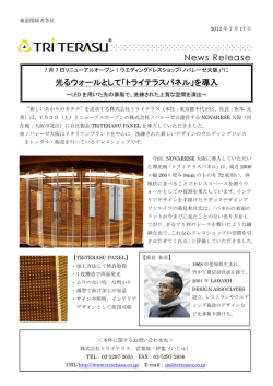
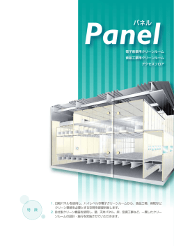
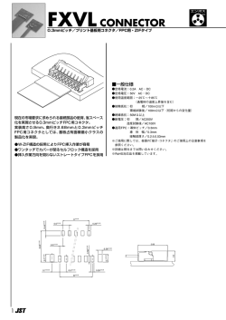
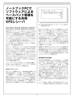
Instruction Sheet
411-78280
取扱説明書
27NOV2008 Rev. A
1.5mm Pitch Mini CT HYBRID Drawer Connector SF Type
1. Introduction
1. はじめに
This instruction sheet covers applications and
この取扱説明書は1.5mmピッチ ミニCT Hybrid
operation producers of 1.5mm pitch Mini CT
ドロワーコネクタ SFタイプの取り扱い方法について
Hybrid Drawer Connector SF Type. Read well
説明しています。御使用前によくお読み下さい。
this instruction sheet thoroughly before you start
また、ミニCTコネクタについては“3. 関連資料”に
operation.
And refer to the standard indicated in
記載されている規格を参照して下さい。
“3. Referential Standard” about Mini CT Connector.
2. Applicable Products
2. 適用製品
この取扱説明書はFig.1の製品に対して適用します。
型番
品
Product Part No.
This instruction sheet is applicable to products
shown in Fig.1.
名
Description
1981536-1
リセプタクル アッセンブリ
ミニCT HYBRID ドロワーコネクタ SFタイプ
Receptacle Assembly,
Mini CT Hybrid Drawer Connector SF Type
1981537-1
プラグ アッセンブリ
ミニCT HYBRID ドロワーコネクタ SFタイプ
Plug Assembly,
Mini CT Hybrid Drawer Connector SF Type
タブ コンタクト
Tab Contact,
ミニCT HYBRID ドロワーコネクタ
Mini CT Hybrid Drawer Connector
リセプタクル コンタクト
Receptacle Contact,
ミニCT HYBRID ドロワーコネクタ
Mini CT Hybrid Drawer Connector
リセプタクル グランド コンタクト
Receptacle GND Contact,
ミニCT HYBRID ドロワーコネクタ
Mini CT Hybrid Drawer Connector
×-353293-×
リセプタクル アッセンブリ
ミニCTコネクタ 圧接タイプ
Receptacle Assembly,
Mini CT Connector MT Type
×-353907-×
リセプタクル コンタクト
ミニCTコネクタ 圧着タイプ
Receptacle Contact,
Mini CT Connector CRIMP Type
×-353908-×
圧着タイプ用 リセプタクル ハウジング
ミニCTコネクタ 圧着タイプ
Receptacle Housing for CRIMP Contact,
Mini CT Connector CRIMP Type
x-1981377-x
x-1981378-x
x-1981379-x
Fig. 1
タイコ エレクトロニクス アンプ株式会社 (〒213-8535 川崎市高津区久本 3-5-8)
1 of
Tyco Electronics AMP K.K. (3-5-8 Hisamoto Takatsu-ku Kawasaki, 213-8535)
この文書の改版の確認は本社、支店へお問い合わせください。 This document is subject to change. Call local AMP for the latest revision.
© Copyright 2003 by Tyco Electronics AMP K.K. All rights reserved.
* : 商標 Trademark
14
Instruction Sheet
411-78280
取扱説明書
3. Referential Standard
3.関連資料
製品名
Product Name
製品規格
Product
Specification
取付適用規格
Application
Specification
取扱説明書
Instraction
Sheet
1.5mmピッチ ミニCT Hybrid ドロワーコネクタ SFタイプ
1.5mm Pitch Mini CT DC Drawer Connector SF Type
108-78479
114-5427
411-78280
1.5mmピッチ ミニCTコネクタ 圧接タイプ
1.5mm Pitch Mini CT Connector MT Type
108-60018
114-5223
1.5mmピッチ ミニCTコネクタ 圧着タイプ
1.5mm Pitch Mini CT Connector CRIMP Type
108-60025
114-5245
日本語/Japanese
411-51001-1
英語版/English
411-51001
Fig.2
4. Product Discription
4.製品説明
本コネクタの構成は下記の部品、名称で
This connector consist of the under-mentioned
構成されています。
components, and name of each component and its
configuration are as illustated below.
ミニ CT コネクタ 嵌合部
Mini CT Connector mating area
AC コンタクト 挿入部
AC Contact insertion area
パネルロック
Panel Lock
パネルロック
Panel Lock
リセプタクル アッセンブリ
Receptacle Assembly
プラグ アッセンブリ
Plug Assembly
Fig.3
Rev. A
2 of 14
Instruction Sheet
411-78280
取扱説明書
プラグ アッセンブリ
Plug Assembly
リセプタクル アッセンブリ
Receptacle Assembly
リセプタクル ハウジング
Receptacle Housing
リセプタクル GND コンタクト
Receptacle GND Contact
嵌合状態
Mating Condition
プラグ ハウジング
Plug Housing
タブ コンタクト
Tab Contact
リセプタクル タブ コンタクト
Receptacle Tab Contact
プラグ スプリング コンタクト
Plug Spring Contact
断面 A-A
SECT A-A
プラグ ハウジング
Plug Housing
リセプタクル ハウジング
Receptacle Housing
タブ コンタクト
Tab Contact
リセプタクル コンタクト
Receptacle Contact
リセプタクル タブ コンタクト
Receptacle Tab Contact
断面 B-B
SECT B-B
プラグ スプリング コンタクト
Plug Spring Contact
Fig.4
Rev. A
3 of 14
Instruction Sheet
411-78280
取扱説明書
5. Handling of Operation
5. 取扱方法
5.1 コンタクトのハウジングへの装着
ハウジングへの装着は、コンタクト挿入穴に対して真っ直
ぐに入れて下さい。(a)
真っ直ぐな状態でコンタクトをハウジングの奥まで完全に
挿入して下さい。(b)
不完全な挿入状態の場合、ハウジングにコンタクトロック
が掛からずに、容易にコンタクトが外れてしまいます(c)。
5.1 Insallation on Contact of Housing
Please put it straight possession loading slot when
you install it in Housing. (a)
Please insert Contact in the Housing
completely.(b)
The lock is not done when it is imperfect insertion
and Contact comes off easily.(c)
リセプタクル アッセンブリ
Receptacle Assembly
リセプタクル コンタクト
Receptacle Contact
リセプタクル GND コンタクト
Receptacle GND Contact
(a) 真っ直ぐにコンタクトを押す
コンタクト装着部
Contact inserts part
プラグ アッセンブリ
Plug Assembly
タブ コンタクト
Tab Contact
コンタクト装着部
Contact inserts part
Push a Contact straightly
OK
OK
(b) ハウジングの奥まで、完全に挿入。
Please insert Contact in the Housing
completely.
NG
NG
(c) ハウジングにコンタクトロックが掛かっていない。
The lock is not done.
Fig.5
Rev. A
4 of 14
Instruction Sheet
411-78280
取扱説明書
5.2 Notes of Panel
5.2 パネルの注意点
顧客用図面に記載する推奨寸法以外のパネルを使用
Do not use a panel with the dimension and
しないこと。
thickness exceeding the recommended limits.
また、パネルの材料に金属材料を用いる場合、コネクタ
を取り付ける際、パネル穴コーナー部のバリやエッジが
コネクタのハウジングに食いついたり、または削られた
And, when metal material is used for the material
of a panel, in case a connector is attached in a
panel, the burr and edge of an corner of a panel
hole bite the housing of a connector or are
りしてコネクタの取り付けが困難になることがあります。
scraped it, and attachment of a connector may
金属パネルを御使用される場合には、コーナー部のバ
become difficult.
リを無くしたり、更にコネクタを取り付け易くする為、コネ
In using of the metal panel, remove a burr, and in
クタ取付方向の面にテーパーや面取りを付けて下さる
order to make a connector further easy to attach,
様、御配慮願います。
add a taper or a chamfer in the surface of
insertion direction to a panel.
a) テーパー
Taper
テーパー
Taper
コネクタ取付方向
Connector insertion direction
b) 面取り
Chamfer
断面 A-A
SECT A-A
全周面取り
All Round Chamfer
コネクタ取付方向
Connector insertion direction
Fig.6
Rev. A
Fig.7
5 of 14
Instruction Sheet
411-78280
取扱説明書
5.3 Axial Gap of Panel
5.3 パネルの軸ずれ
本コネクタのフローティング量はX方向0.9mm以下/
The floating amount of this connector is
Y方向0.8mm以下です。Fig.8の様に、パネルの軸ずれ
X direction:0.9mm MAX/ Y direction:0.8mm MAX.
As shown in Fig.8, set the axial gaps of a panel to
量はX方向0.9mm以下/Y方向0.8mm以下に
X direction:0.9mm MAX/ Y direction:0.8mm MAX.
して下さい。
パネル開口部
PANEL OPENING
断面 C-C
SECT C-C
断面 D-D
SECT D-D
パネル開口部
PANEL OPENING
パネル開口部
PANEL OPENING
断面 E-E
SECT E-E
断面 F-F
SECT F-F
Fig.8
5.4 コネクタの取り扱い方法
5.4 Handling of Connector Body
ドロワーコネクタの接触部及びミニCTコネクタ嵌合部、
Never try to insert the tip end of screw driver, test
またミニCTコネクタの接触部にはドライバーの先、
prove or other similar pins into the contact mating
チェッカーのプローブ等の異物を差し込まないように
して下さい。
<注意>
area of Drawer Connector and Mini CT
Connector.
<Note>
コネクタに異物を差し込むと、めっきの剥離及び端子
This action will result in scratched,
変形の原因となります。
and/or deformation of contact.
Rev. A
6 of 14
Instruction Sheet
411-78280
取扱説明書
5.5 Attach Receptacle Assembly in Panel
5.5 リセプタクル アッセンブリの取り付け方法
Fig.9に示す様に、パネル穴にコネクタの左右のパネル
As shown in Fig. 9, in the state where the panel
ロックが均等に掛かっている状態で(a)、真っ直ぐにコネ
hole is panel locked on either side equally of the
connector (a), push a connector straightly and
クタを押してパネルに取り付けて下さい(b)。
attach in a panel (b).
<確認項目>
<Check Items>
1. パネルロックに破損、クラック等が無いこと。
1. Breakage, crack, etc. should not be in a panel
lock of Drawer Connector.
2. コネクタがパネルにロックされていること。
2. Pay attention to be locked by the panel.
リセプタクル アッセンブリ
Receptacle Assembly
両側のパネルロックがパ
(b) 装着完了
Finished
ネルにロックされている
こと
The both panel locks of
(a) 真っ直ぐにコネクタを押す
connector are locked in
Push a connector straightly
the panel.
Fig.9
Rev. A
7 of 14
Instruction Sheet
411-78280
取扱説明書
5.6 Attach PLUG Assembly in Panel
5.6 プラグ アッセンブリの取り付け方法
Fig.10に示す様に、片側のパネルロックをパネルに装
As shown in Fig. 10, hang a panel lock of one
着し(a)、そのロックを支点として(b)、支点側に寄せなが
side on the panel (a), and using the lock as a
fulcrum (b), rotate a panel lock of another side
らもう片方のパネルロックを回転させて(c)、パネルに取
and bring near by the fulcrum side (c), and attach
り付けて下さい(d)。
in a panel (d).
<確認項目>
<Check Items>
1. パネルロックに破損、クラック等が無いこと。
1. Breakage, crack, etc. should not be in a panel
lock of Drawer Connector.
2. コネクタがパネルにロックされていること。
2. Pay attention to be locked by the panel.
(a) 片側のパネルロックを
装着する
(a)Hang the panel lock of
one side on panel
(b)支点
(b)Fulcrum
(c)コネクタを支点側に寄せる
(c)Bring near by the fulcrum side
両側のパネルロック
がパネルにロックさ
れていること
The both panel
(c)回転する
(d)装着完了
locks of connector
(c)Rotate
(d)Finished
are locked in the
Fig.10
Rev. A
panel.
8 of 14
Instruction Sheet
411-78280
取扱説明書
5.7 Inclination of Connector and Housing
5.7 コネクタとパネルの傾き
Fig.11に示す様に、コネクタ嵌合開始時の傾き角度
As shown in Fig. 11, Please control the inclination
は、パネルの傾きを含め、3度以内に抑えてください
angle when inserting start in a connector within
3 degrees including inclination of a panel(a)(b).
(a)(b)。また、パネルへの取り付けは、コンタクトが水
Moreover, as for the attachment to a panel,
平になるように取り付けして下さい(c)。
contact should be horizontally located in a line(c).
リセプタクル アッセンブリ
Receptacle Assembly
リセプタクル パネル
Receptacle Panel
プラグ アッセンブリ
Plug Assembly
プラグ パネル
Plug Panel
OK
(a) パネルの傾き含め、コネクタの傾きが 3°以内。
The inclination of Panel including inclination of
Connector should be less than 3 degrees.
Exceed 3°
NG
(b) コネクタの傾きが 3°以上
NG
(c) コネクタ取り付け方向がパネルに対して垂直
There is 3 degrees or more of inclination.
The attachment direction of Connector is
perpendicular to Panel.
Fig.11
Rev. A
9 of 14
Instruction Sheet
411-78280
取扱説明書
5.8 Mate Mini CT Connector
5.8 ミニCTコネクタの嵌合方法
Fig.12に示す様に、ミニCTコネクタを真っ直ぐに嵌合
As shown in Fig.12, mate Mini CT connector
して下さい。
straightly.
<確認項目>
<Check items>
Fig.13の様にミニCTコネクタの電線保持部がロックさ
As shown in Fig.13, the wire support area of Mini
れ、コネクタが半嵌合(半挿入)状態でないこと。
CT connector should be locked. Pay attention to a
semi-mating (improper mating) of the connector.
ミニ CT コネクタ
Mini CT Connector
ミニ CT コネクタ
Mini CT Connector
プラグ アッセンブリ
リセ アッセンブリ
真っ直ぐにミニ CT コネクタを嵌合する
Rec. Assembly
Mate Mini CT Connector straightly
Plug Assembly
Fig.12
ミニ CT コネクタの電線保持部が
ロックしていること
The wire support area of Mini CT
connector should be locked.
ミニ CT コネクタの電線保持部が
ロックしていること
The wire support area of Mini CT
connector should be locked.
プラグ アッセンブリ
Plug Assembly
リセ アッセンブリ
Rec. Assembly
Fig.13
Rev. A
10 of 14
Instruction Sheet
411-78280
取扱説明書
5.9
5.9 リセ アッセンブリの取り外し方法
Fig.14の様に、両側のパネルロックを押し下げながら
Remove Rec. Assembly from Panel
As shown in Fig. 14, remove a connector straightly
(b), depressing the panel lock of both sides (a).
(a)、コネクタを真っ直ぐに取り外して下さい(b)。
<注意>
<Note>
取り外したコネクタは再使用しないで下さい。
Do not re-use the removed connector. Replace this
必ず新品と交換して下さい。
with new one.
押す
Push
押す
Push
(a) パネルロックを押し下げる
Depressing the panel lock of both sides.
(b) コネクタを真っ直ぐに取り外す
Remove a connector straightly.
Fig.14
Rev. A
11 of 14
Instruction Sheet
411-78280
取扱説明書
5.10 Remove PLUG Assembly from Panel
5.10 プラグ アッセンブリの取り外し方法
Fig.15の様に、両側のパネルロックを押し下げながら
(a)、コネクタを真っ直ぐに取り外して下さい(b)。
As shown in Fig. 15, remove a connector straightly
(b), depressing the panel lock of both sides (a).
<注意>
<Note>
取り外したコネクタは再使用しないで下さい。
Do not re-use the removed connector. Replace this
必ず新品と交換して下さい。
with new one.
押す
Push
(b) パネルロックを押し下げる
Depressing the panel lock.
(a) コネクタを片側に寄せる
Bring a connector near by one side.
(c)支点
(c)Fulcrum
(e)取り外し完了
(d)回転する
(e)Finished
(d)Rotate
Fig.15
Rev. A
12 of 14
Instruction Sheet
411-78280
取扱説明書
5.11
5.11 ミニCTコネクタの取り外し方法
Unmate Mini CT Connector
Fig.16及びFig.17の様にドロワーコネクタのロックを
As shown in Fig. 16 and Fig.17, straightly unmate
押し上げながら、ミニCTコネクタを真っ直ぐに取り外し
Mini CT Connector from Drawer Connector after
pushing a lock of Drawer connector.
て下さい。
<注意>
<Note>
1. 電線を1本(または数本)のみを持ってミニCT
1. Do not unmate Mini CT Connector from
Drawer Connector by grasping only one or
コネクタをドロワーコネクタから引き抜かないこと。
a few wires.
2. ロックを押し上げないでミニCTコネクタ
2. Do not unmate Mini CT Connector from
を取り外さないこと。
Drawer Connector without pushing a lock of
ロックが壊れる原因になります。
Drawer Connector.
This action will cause cracks on a lock.
リセ アッセンブリ
Rec Assembly
プラグ アッセンブリ
Plug Assembly
Fig.16
ミニ CT コネクタを真っ直ぐに取り外す
Remove Mini CT connector straightly.
ロックを押し上げる
Push a lock
ミニ CT コネクタを真っ直ぐに取り外す
Remove Mini CT connector straightly.
ロックを押し上げる
Push a lock
リセ アッセンブリ
Rec Assembly
プラグ アッセンブリ
Plug Assembly
Fig.17
Rev. A
13 of 14
Instruction Sheet
411-78280
取扱説明書
6
6.ハーネス
Harness
ハーネスの取り扱いは通常のコネクタと同様ですが、
Handling of the harness will be the same with that
ミニCTコネクタに急な力が加わらない様に注意する
of common connectors. Care should be taken not
to jerk the wire during handling.
必要があります。
Fig.18の様に、テーピングはコネクタ端より30mm以上
離れたところにして下さい。束ねられる電線に引張力が
When fixing the wires, the wires should be given
some play and no tention. The wire taping should
be made at a position approx. 30mm or more
加わらないようにして下さい。特に、両端の電線は多少
away from the connector end as illustrated in
長さに余裕を持たせて下さい。
Fig.18. Fix the wires with a tape without putting
またFig.19の様にハーネスを引き回す際、電線が引っ
any tention to any of the bundled wires.
張られないよう、ハーネスを曲げて遊びを持たせて下さ
Particularly both ends of the bundled wires must
い。
be given same slack.
And bend the wires with same play as illustrated
in Fig.19.
テーピング又はタイバンド
Taping or Tie band
Fig.18
テーピング又はタイバンド
Taping or Tie band
電線が引っ張られる
This wire is being pulled.
NG
OK
Fig.19
Rev. A
14 of 14
© Copyright 2026 Paperzz