12TH EDITION
09 20 00/NGC
National Gypsum
Construction Guide
В®
HOW TO USE THE NATIONAL GYPSUM COMPANY
GYPSUM CONSTRUCTION GUIDE
NATIONAL GYPSUM PRODUCTS FOR ALL YOUR
BUILDING NEEDS
Your National Gypsum Company “Gypsum Construction
Guide” has been carefully developed to provide you with a
comprehensive guide to the entire range of National Gypsum
products. We have attempted to give you the most accurate,
up-to-date information in a clear, concise, easy-to-read
format. Because it is important for us to ensure our guide is
user-friendly, we welcome your comments. Please write
us at: National Gypsum Company Technical Services
Department, 2001 Rexford Road, Charlotte, N.C. 28211 or
call 1-800-NATIONAL (1-800-628-4662) U.S.A. or Canada.
For your easy reference and accessibility to this information, we
have placed all of our Sweet’s material in this section. For a
complete copy of our literature call 1-800-NATIONAL.
TRADEMARKS
The following names are trademarks owned by National
Gypsum Company or its subsidiary, National Gypsum
Properties, LLC:
DURABASEВ®
DURASANВ®
EASY FINISHВ®
EDGE GRIP TM
EXCELLENCE ACROSS
THE BOARDВ®
e2XPв„ў
E-Z S TRIPВ®
FIRE-SHIELDВ®
FIRE-SHIELD C TM
GOLD BONDВ®
GOLD BOND 54В®
GRIDMARXВ®
GRIDSTONEВ®
GYPSOLITEВ®
HIGH FLEXВ®
HI-ABUSEВ®
HI-IMPACTВ®
KAL-KOREВ®
KAL-KORNER BEADВ®
CAD DRAWINGS AND SPECIFICATIONS
To assist you in your design process, all CAD drawings and
specifications are available at www.nationalgypsum.com.
Computer aided design (CAD) drawings are in DXF, DWG and
GIF file formats. Specifications are in CSI three-part format and
CSI page format. Additional specification options are provided in
Masterspec and Manu-Spec.
SUB-SECTION HEADING
Each product in the section will be
designated with a sub-section
heading on the appropriate pages.
COLOR ARROW HEAD
Indicates next topic
for a product, i.e.
Description,
Technical Data,
Details,
Specifications,
Recommendations,
Installation.
KAL-KOTEВ®
KAL-MESHВ®
MULTI-FLEXВ®
NGCВ®
1-800 NATIONALВ®
PERFECT SPRAYВ®
PERMABASEВ®
PERMABASE FLEXВ®
PROFORMВ®
SEASPRAY MVRВ®
SHAFTLINERВ®
SHAFTLINER XPВ®
SOUNDBREAKв„ў
STA-SMOOTHВ®
TRIPLE-TВ®
ULTRATM
UNI-KALВ®
X-KALIBURВ®
XPВ®
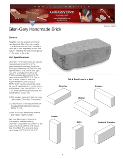
Suspended Metal Lath Ceilings
DESCRIPTION
Metal lath suspensions are
commonly made below
virtually all types of
construction for fire-rated
and non fire-rated plaster
ceilings. Framing of 1 1/2"
C.R. channels are spaced
up to 4' o.c. perpendicular
to joists and are crossfurred with 3/4" C.R.
channels spaced according
to specifications for types
and weight of metal lath.
Lath is then properly
lapped at sides and ends
and tied every 6" to the
3/4" channel.
Where it is advisable to install
unrestrained ceilings,
having perimeters
separated from adjacent
walls or partitions,
galvanized casing beads
should be installed around
the periphery.
Metal Lath is frequently used
for furred as well as
suspended ceilings.
Metal lath is used for furring
from wood, concrete and
steel joists.
RECOMMENDATIONS
1. Control joints should be
installed in ceilings without
perimeter relief with a maximum distance between
such joints of 30' with a
maximum undivided area
of 900 sq. ft. With perimeter relief, maximum distance is 50' with maximum
undivided area of 2500
sq.ft.
2. Use three-coat plastering on
metal lath.
GRAPHICS, ILLUSTRATIONS AND
PHOTOGRAPHY
Each product grouping is
full of informative graphics and
photography as a visual aid in
identifying products, uses and
installation.
TECHNICAL DATA
SIZE AND SPACING OF CHANNEL FOR SUSPENDED CEILINGS
Center to
Center Spacing
of Hangers
Along Channel
Main Channel
Size of
(weight
Maximum
Cold Rolled per 1000 ft.)
Center to Center
Channel
(305 M)
Spacing of Channel
up to 3'
(914 mm)
1 1/2"
(38.1 mm)
475 lbs.
(216 kg)
4'
(1219 mm)
up to 3'6"
(1067 mm)
1 1/2"
(38.1 mm)
475 lbs.
(216 kg)
3'6"
(1067 mm)
up to 4'
(1219 mm)
1 1/2"
(38.1 mm)
475 lbs.
(216 kg)
3'
(914 mm)
SIZE AND SPACING OF CHANNEL FOR FURRED
AND SUSPENDED CEILINGS
Center to Center
Spacing of Hangers
3/4" (19.0 mm) C.R. Channel
Cross Furring 300 lbs.
(136 kg)/1000 ft. (305 M)
Maximum
Furring
Spacing
up to 3' (914 mm)
up to 3' (914 mm)
up to 3'6" (1067 mm)
up to 4' (1219 mm)
3/8" (9.5 mm) rib lath
3.4 lb. (1.5 kg) flat rib lath
3.4 lb. (1.5 kg) mesh lath
2.5 lb. (1.1 kg) mesh lath
24" (610 mm)
19" (483 mm)
16" (406 mm)
12" (305 mm)
MAXIMUM SPACING OF SUPPORTS FOR METAL LATH
Support
Spacing
Type of Lath
Diamond Mesh
(flat expanded)
DETAILS
Weight of Lath
lbs. per sq. yd. (kg/m2)
16" (406 mm)
3.4 (1.9)
Flat Rib
16" (406 mm)
19" (483 mm)
2.75 (1.5)
3.4 (1.9)
3/8" (9.5 mm) Rib
24" (610 mm)
3.4 (1.9)
HANGER WIRE
3/4" C.R.
CHANNEL
CAD DRAWINGS
These drawings are included where
appropriate to assist architects and
specifiers with detailed drawings.
HANGER WIRE
1 1/2" C.R.
CHANNEL
1 1/2" C.R.
CHANNEL
TIE WIRE
3/4" C.R.
CHANNEL
1 1/2" C.R.
CHANNEL
GYPSUM PLASTER
GYPSUM
PLASTER
66 CASING BEAD
PAGE NUMBER
FLEXIBLE DUST SEAL
FINISHED WALL LINE
66 CASING BEAD
SUSPENDED METAL LATH AT WALL (UNRESTRAINED)
09210K
Scale: 3" = 1'-0"
40
METAL LATH
METAL LATH
NO. 15
EXPANSION JOINT
LIGHTING TROFFER
SUSPENDED METAL LATH CONTROL JOINT
09210O
Scale: 1 1/2" = 1'-0"
09210M
Scale: 3" = 1'-0"
NATIONAL GYPSUM CONVENTIONAL PLASTER SYSTEMS
В®
National Gypsum Company Headquarters
2001 Rexford Road
Charlotte, North Carolina 28211
(704) 365-7300
Internet - www.nationalgypsum.com
COPYRIGHT 2008 NATIONAL GYPSUM COMPANY
SUB-SECTION NAME
Repeats the name of the
current sub-section.
CAD DRAWING FILE
NUMBER
GENERAL
REFERENCE
GENERAL REFERENCE
National Gypsum Company is a fully integrated manufacturer
and supplier of building and construction products worldwide.
Our primary emphasis is on Gold BondВ® BRAND gypsum
board, ProFormВ® BRAND joint treatment products, PermaBaseВ®
BRAND cement board, and gypsum plaster systems.
Based in Charlotte, NC, the privately held National Gypsum
Company operates more than 40 facilities throughout the
U.S. and Canada.
Charlotte, North Carolina, is the home of the new National
Gypsum Company.
TABLE OF CONTENTS
Product Specification Directory .........................................................................3
В®
В®
0 9 2 9 0 0 Hi-Impact BRAND XP Gypsum Board.........................................81
Sound and Fire Rated Assemblies ......................................................................8
0 9 2 9 0 0 SoundBreakв„ў Gypsum Board ....................................................84
Quick Selector for Fire and Sound Rated Systems..............................................9
0 9 2 9 0 0 Gridstone BRAND Ceiling Panels...................................................86
Gypsum Plaster Partitions – Metal Lath.........................................................11
0 9 2 9 0 0 Gridstone BRAND Cleanroom Ceiling Panels ...............................87
Plaster Fireproofing Columns (10WF40 or heavier)......................................12
0 9 2 9 0 0 GridstoneВ® BRAND Hi-Strength Ceiling Panels .............................88
Plaster Fireproofing Beams (8WF24 or heavier) ...........................................12
0 9 2 9 0 0 Gold BondВ® BRAND Foil Back Gypsum Board .............................89
Veneer Plaster Partitions – Wood and Steel Framing....................................12
0 9 2 9 0 0 Gypsum Systems Nonload-Bearing Steel Frame Partitions .........90
Gypsum Board Partitions – Wood Framing (Load-Bearing) ..........................12
0 9 2 9 0 0 Drywall Metal Framing ...............................................................93
Gypsum Board Partitions – Steel Framing.....................................................14
0 9 2 9 0 0 Accessories .................................................................................94
Gypsum Board Partitions – Steel Framing (Load-Bearing) ............................18
0 9 2 9 0 0 Steel Frame Ceilings/Furring Channels or Studs...........................99
Gypsum Board Partitions – Durasan Prefinished Gypsum Board..................18
0 9 2 9 0 0 Wood Frame Walls and Ceilings ..............................................101
Gypsum Board Partitions – Solid..................................................................19
0 9 2 9 0 0 Resilient Furring Channel Construction ....................................106
Gypsum Board Partitions – Shaftwalls, Area Sep. Walls...............................20
0 9 2 9 0 0 Gypsum Board Over Masonry .................................................108
Gypsum Board Column Fireproofing............................................................21
0 9 2 9 0 0 Solid Laminated Partitions.........................................................110
Gypsum Board Beam Fireproofing ...............................................................22
0 9 2 9 0 0 ProFormВ® BRAND Joint Treatment ...............................................112
Gypsum Board Floor/Ceilings – Wood Framing...........................................22
0 9 2 9 0 0 ProFormВ® BRAND Texture Products .............................................115
Gypsum Board Roof/Ceilings – Wood Framing ...........................................23
0 9 2 9 0 0 Levels of Gypsum Board Finish .................................................118
Gypsum Board Floor/Ceilings – Steel Framing .............................................24
09 21 16.23
Gypsum Board Roof/Ceilings – Steel Framing..............................................26
09 21 16.23 Horizontal Shaftwall Duct and Ceiling Assemblies...................137
Gypsum Board Horizontal Shaftwall Duct Protection..................................26
09 21 16.33 H-Stud Area Separation Wall System ........................................139
0 6 1 6 4 3 Gold BondВ® BRAND Gypsum Sheathing and e2XP Extended Exposure Sheathing ....27
0 9 2 8 0 0 PermaBaseВ® BRAND Cement Board.............................................145
Cavity Shaftwall Systems...........................................................123
0 9 2 3 0 0 Conventional Plaster Systems...........................................................................33
INDEX
Index .........................................................................................157
0 9 2 6 1 3 Veneer Plaster Systems ....................................................................................43
INDEX
Index of CAD Detail Drawings..................................................161
0 9 2 9 0 0 Gypsum Board Systems ...................................................................................57
0 9 2 9 0 0 Gold BondВ® BRAND GridMarXВ® Gypsum Board ................................................64
0 9 2 9 0 0 Gold BondВ® BRAND Gypsum Board ..................................................................65
0 9 2 9 0 0 Gold BondВ® BRAND Fire-ShieldВ® Gypsum Board ..............................................66
0 9 2 9 0 0 Gold BondВ® BRAND Sta-Smooth Gypsum Board ...............................................67
0 9 2 9 0 0 Gold BondВ® BRAND XPВ® Gypsum Board ...........................................................70
0 9 2 9 0 0 Gold BondВ® BRAND Exterior Soffit Board ...........................................................71
0 9 2 9 0 0 Gold BondВ® BRAND 1" Fire-ShieldВ® Shaftliner....................................................73
0 9 2 9 0 0 Gold BondВ® BRAND 1" Fire-ShieldВ® Shaftliner XPВ® .............................................74
0 9 2 9 0 0 High Flex BRAND Gypsum Board ......................................................................75
Our vision: To be recognized as the industry leader for extraordinary
service and products that consistently meet our customers’ toughest
standards.
Driving and sustaining our Vision are these core Values:
•
•
•
•
•
Customer satisfaction as our priority
Honesty, integrity, fairness and respect
Communications and openness with all those with whom we deal
Teamwork, empowerment and continuous improvement
Work hard, be safe, and have fun
0 9 2 9 0 0 Gold BondВ® BRAND High Strength Ceiling Board ..............................................77
0 9 2 9 0 0 Gold BondВ® BRAND Hi-AbuseВ® XPВ® Gypsum Board ..........................................78
NATIONAL GYPSUM GENERAL REFERENCE
1
NATIONAL GYPSUM COMPANY
such systems, products are evaluated
together as complete building
assemblies – walls,
partitions, floors
and ceilings.
Before National
Gypsum releases a
system to the building industry, the system is thoroughly
tested and the
results are correlated
and charted, making
it easier for the
builder or architect
to match a system to
National Gypsum’s own
his needs or to
building codes. This patented Calcidyne system
heats the land plaster to
extensive database
remove 75% of the water
of technical inforwhich is chemically combined
mation is made
in the gypsum molecules.
National Gypsum’s Technology Innovation Center is located in
available to you not
Charlotte, North Carolina. National Gypsum has always held a leaderonly through techniPerformance tests are
ship role in the development of gypsum based products and systems.
cal bulletins such as
conducted according to
Many of today’s most innovative gypsum, joint treatment and cement
this one, but also
accepted national stanboard products and systems were developed, tested and introduced by
through our technidards under controlled labNational Gypsum Company.
cal support network.
oratory conditions to miniThe construction systems
mize variances and to perYOUR TECHNICAL
Gypsum products you need
referred to in this manual
mit comparison of test
RESOURCE
and specify are right for
are designed and tested
results of all types of systhe
job.
They
are
backed
Today, more than ever, clear,
with material manufactured
tems, similar and dissimilar.
up
by
thoroughly
trained
accurate information is vital
by National Gypsum.
Customer Service
Detailed recommendations
to every construction job.
Substitutions of other
Representatives who can
are contained in each secThe challenges of construcproducts or brands for
also
help
with
product
tion. Architects, structural
tion continue to grow:
National
Gypsum
Products
selection and purchase.
engineers or others who
increasingly innovative
are not recommended.
are responsible for field
building designs, tighter
Continuing Research. Because
Field Installation of tested sysinstallations must make
budgets, tighter schedules,
the building industry and
tems must be identical to
their own determinations
and the continuing develbuilding codes are conthe laboratory installation
concerning the applicabiliopment of new materials
stantly changing, National
to produce optimum perty of the laboratory perforand construction techGypsum maintains a fullformance of these systems,
mance test results to the
niques.
scale research center that
though duplication of condesign or construction of
continually tests and evaluA NETWORK OF
trolled, laboratory results
any specific structure.
ates
products,
applications,
TECHNICAL SUPPORT
in such field installations is
construction systems and
not guaranteed.
In keeping with the corporate
techniques.
mission to become the preImmediate Answers. Of
ferred supplier for our cuscourse, there are times
tomers, National Gypsum
when you need an answer
has made a total committo a pressing situation or
ment to technical assisquestion. For this reason,
tance and created a netNational Gypsum has set
work of support to provide
up our Technical
valuable assistance at every
Assistance Hotline:
stage of a project’s devel1-800-NATIONAL
opment.
(1-800-628-4662).
Field Representation. Before
One toll-free phone call gives
construction begins, while
a direct, personal link to a
plans and specifications are
technical expert with up-tobeing produced, these
date knowledge of specifiexperienced, trained procations, building codes,
fessionals provide
product information and
technical consultation
much more.
in selecting, specifying
and using gypsum-based
QUALITY IS SYSTEMATIC
building materials.
At the National Gypsum
During the construction
Research Center, we
National testing organizations frequently participate in the
phase, our Field
concentrate not only on
many product tests conducted at NGC Testing Services. Fire,
Representatives have the
building products individuacoustical, structural and analytical test laboratories are
experience and the training
ally but also on complete
available commercially through NGC Testing Services for
to assure that the National
construction systems. In
other manufacturers and research interests. For information,
call 716-873-9750 or www.NGCTestingServices.com.
SM
2
NATIONAL GYPSUM QUICK SELECTOR/GENERAL REFERENCE
PRODUCT SPECIFICATION DIRECTORY
GENERAL
REFERENCE
GENERAL REFERENCE
FOREWORD
This directory is designed to provide a convenient, up-to-date
reference to some of the products marketed by National
Gypsum Company, and to the ASTM and Federal
Specifications with which they comply.
The General Services Administration has cancelled many Federal
procurement documents. These have been superseded by
ASTM Specifications. Federal Specifications are listed for
reference.
For the key to Federal Specification, gypsum board and joint
treatment product designations (Type, Form, etc.), refer to
table on page 7.
This is to certify that the following materials comply in all
respects with listed specifications.
GYPSUM BOARD PRODUCTS
Product
Gypsum
Board
Specification Standards
ASTM
Federal
Regular Gypsum
Board or Sta-Smooth
Fire resistant. Will take decoration after proper
surface preparation of interior walls and ceilings.
Description and Use
C 1396
SS-L-30D Type III
XP Gypsum Board
1/2" (12.7 mm) gypsum board with a
moisture resistant gypsum core and mold/mildew
resistant purple paper. Will take decoration after
proper surface preparation of interior walls and ceilings.
C 1396
SS-L-30D Type III
Fire-Shield Gypsum
Board (Includes “C”)
1/2" (12.7 mm) and 5/8" (15.9 mm) gypsum
board with specially processed core highly
resistant to fire; type X core.
C 1396
Type X
SS-L-30D Type III
Grade X
XP Fire-Shield Gypsum
Board (Includes “C”)
1/2" (12.7 mm) and 5/8" (15.9 mm) gypsum
board with a moisture resistant gypsum
core highly resistant to fire and mold/mildew
resistant purple paper; type X core.
C 1396
Type X
SS-L-30D Type III
Grade X
SoundBreak
Gypsum Board
5/8" (15.9 mm) acoustically enhanced gypsum
board used in construction of high rated STC
assemblies.
C 1396
SS-L-30D Type III
Foil Back Gypsum
Board
Standard gypsum board with aluminum foil
on backside providing vapor retarder for interior
walls and ceilings.
C 1396
SS-L-30D Type III
Form C
Fire-Shield Shaftliner
(Includes XP)
1" (25.4 mm) thick, 2' (610 mm) wide, for solid
partitions, shaft walls and Area Separation Walls;
type X core.
C 1396
Type X
SS-L-30D Type IV
Grade X
Regular or Fire-Shield
Exterior Soffit Board
Gypsum board with extra resistance to
moisture and sagging used for exterior soffit.
C 1396
Type X
None
Durasan Prefinished
Regular Gypsum Board
Gypsum board with a vinyl surface, combines
texture and pattern in colors. No decoration required.
C 1396
SS-L-30D Type III
Class 3
Durasan Prefinished
Fire-Shield Gypsum Board
Gypsum board with a vinyl surface, combines
texture and pattern in colors; type X core.
C 1396
Type X
SS-L-30D Type III
Grade X Class 3
High Flex Gypsum Board
1/4" (6.4 mm) flexible gypsum board designed for
use in radius wall and ceiling construction.
C 1396
SS-L-30D Type III
High Strength
Ceiling Board
1/2" (12.7 mm) gypsum board with core formulated
to provide increased sag resistance.
C 1396
SS-L-30D Type III
Hi-Abuse XP Fire-Shield
Gypsum Board
5/8" (15.9 mm) gypsum board with heavy abrasion
resistant mold/mildew resistant purple paper and a
special core to provide greater resistance to surface
indentation; type X core.
C 1396
Type X
SS-L-30D Type III
Grade X
Hi-Impact XP Fire-Shield
Gypsum Board
5/8" (15.9 mm) gypsum board with heavy
abrasion resistant mold/mildew resistant purple
paper and a special moisture resistant gypsum core
backed with reinforcing fiber glass mesh; type X core.
C 1396
Type X
SS-L-30D Type III
Grade X
Gridstone Ceiling Panels
1/2" x 2' x 2' (12.7 mm x 610 mm x 610 mm)
1/2" x 2' x 4' (12.7 mm x 610 mm x 1219 mm)
gird panels with Fire-Shield G type X core and
vinyl laminate.
C 1396
Type X, Class 1;
E 1264, Type XX,
Patterns E, G
None
NATIONAL GYPSUM PRODUCT SPECIFICATION DIRECTORY
3
GYPSUM BOARD PRODUCTS (cont.)
Gypsum
Board
Description and Use
None
Gridstone CleanRoom
Ceiling Panels
1/2" x 2' x 2' (12.7 mm x 610 mm x 610mm)
1/2" x 2' x 4' (12.7 mm x 610 mm x 1219 mm)
grid panels with Fire-Shield G type x core and vinyl
laminate. Completely sealed on face, back and edges.
Durabase Gypsum Board
5/16" (7.9 mm), 3/8" (9.5 mm), 1/2" (12.7 mm),
and 5/8" (15.9 mm) gypsum board for printing
application or laminating base.
C 1396
None
Regular Jumbo Gypsum
Sheathing
1/2" (12.7 mm) gypsum board to be used as
a sheathing for exterior wall construction.
C 1396
SS-L-30D Type II
Fire-Shield Jumbo
Gypsum Sheathing
Sheathing
5/8" (15.9 mm) gypsum board to be used as
sheathing for fire rated exterior wall construction;
type X core.
C1396
Type X
e XP Extended
1/2” (12.7 mm) Regular with a coated fiberglass mat
used as a sheathing for exterior wall construction.
e XP Extended
5/8” (15.9 mm) Type X with a coated fiberglass mat
used as a sheathing for fire-rated exterior wall
construction
2
Exposure Sheathing
C 1396
Type X, Class 1;
E 1264, Type XX,
Patterns E, G
Product
None
SS-L-30D Type II
Grade X
C1177
SS-L0-30D Type II
and applicable sections of
C1396
C1177
SS-L0-30D Type II
and applicable sections of
Grade X
C1396
LATH, DRYWALL JOINT TREATMENT, TEXTURES AND ACCESSORIES
4
C 1396
Class 1
5/16" x 2' x 2' (7.9 mm x 610mm x 610 mm)
5/16" x 2' x 4' (7.9 mm x 610 mm x 1219 mm)
grid panels with non-combustible gypsum core
and vinyl laminate.
2
Joint
Treatment
Federal
Gridstone Hi-Strength
Ceiling Panels
Exposure Sheathing
Lath
ASTM
Specification Standards
Description and Use
ASTM
Federal
Kal-Kore Plaster Base
3/8" (9.5 mm), 1/2" (12.7 mm) gypsum base
for veneer plaster systems.
C 1396
SS-L-30D Type VI
Kal-Kore Fire-Shield
Plaster Base (includes “C”)
1/2" (12.7 mm), 5/8" (15.9 mm) gypsum base for
veneer plaster systems; type X core.
C 1396
Type X
SS-L-30D Type VI
Grade X
Regular or Fire-Shield
Hi-Abuse Kal-Kore
Plaster Base
Gypsum base with special core to provide
greater resistance to surface indentation.
Designed for high abuse areas.
C 1396
Type X
SS-L-30D TypeVI
Grade X
ProForm All Purpose
Joint Compound
A conventional full-weight ready mix joint compound
used for all phases of drywall finishing.
C 475
SS-J-570B
ProForm XP
Joint Compound
A conventional full-weight ready mix joint compound
formulated for additional mold resistance.
C 475
SS-J-570B
ProForm Multi-Use
Joint Compound
A ready mix compound that combines the best attributes
of All Purpose and Lite for use in all phases of drywall
finishing
C 475
SS-J-570B
ProForm Lite
Joint Compound
A full “Lite” weight ready mix for use in finishing gypsum
board, gypsum board joints, spotting fasteners and finishing accessories.
C 475
SS-J-570B
ProForm Ultra
Joint Compound
An all purpose joint compound that pulls and sands easier
than conventional ready mix with up to 50% less shrinkage.
C 475
SS-J-570B
ProForm Taping
Joint Compound
Ready mixed joint compound used to enhance bond when
embedding joint tape and applying cornerbeads and
accessories.
C 475
SS-J-570B
ProForm Topping
Joint Compound
Ready mixed topping compound designed as a finish
coat over joint compound.
C 475
SS-J-570B
ProForm Texture Grade
A nonaggregated, ready mixed material formulated for
texturing interior walls and ceilings.
C 475
SS-J-570B
ProForm Triple-T
Compound
Triple-T is an all-purpose powder product to be job mixed
with water. It is recommended for tape application, finishing
and texturing.
C 475
SS-J-570B
ProForm Sta-Smooth,
Sta-Smooth Lite, and
Sta-Smooth HS Joint
Compounds
A setting type powder compound used for joint finishing.
C 475
SS-J-570B
NATIONAL GYPSUM PRODUCT SPECIFICATION DIRECTORY
GENERAL REFERENCE
Product
Textures
Accessories
Description and Use
Specification Standards
ASTM
Federal
ProForm Perfect Spray
Textures
A white, aggregated spray texture for interior use on
walls and ceilings.
None
None
ProForm Perfect Spray
EM Textures
A white, nonaggregated spray texture for interior use on
walls and ceilings.
None
None
Gypsum Board Cornerbead*
Used to protect exterior corners.
C 1047
None
Gypsum Board Casing Bead*
Used to reinforce and trim around doors and windows.
C 1047
None
Arch Cornerbead*
Used straight for exterior corners or may be snipped and
bent to form arches.
C 1047
None
ProForm Joint Tape
A paper tape for concealment of gypsum board joints.
C 475**
ProForm Fiberglass
Mesh Tape
A self-adhering glass fiber mesh tape to be used only with
setting compounds.
C 475
None
ProForm Multi-Flex
Tape Bead
Used to form inside or outside corners that are less or
greater than 90o.
None
None
E-Z Strip Expansion Joint*
Vinyl extrusion used as an expansion or control joint for
drywall and veneer plaster walls and ceilings.
C 1047
None
.093 Zinc Expansion Joint*
All zinc part used as an expansion or control joint for
drywall and veneer plaster walls and ceilings.
C 1047
None
GENERAL
REFERENCE
LATH, DRYWALL JOINT TREATMENT, TEXTURES AND ACCESSORIES (cont.)
SS-J-570B**
*National Gypsum does not manufacture these products.
FIRE AND SMOKE STOP COMPOUND
Product
Specification Standards
Description and Use
ProForm Sta-Smooth
FS 90 Compound
Setting type product formulated to provide protection in
fire stopping applications through gypsum and other fire
rated assemblies. Meets ASTM E 814 and ANSI/UL 1479.
PLASTER PRODUCTS AND ADDITIVES
Product
Basecoat
Plasters
Finish
Plasters
Special
Additives
ASTM
Federal
None
None
Specification Standards
Description and Use
ASTM
Federal
Gold Bond Two-Way
Hardwall Gypsum Plaster
For use with job-mixed aggregate. Machine spray or
trowel application.
C 28
SS-P-00402B
Type II
Gold Bond
Gypsolite Plaster
Mill-mixed with perlite. Add only water on the job.
C 28
SS-P-00402B
Type I
Kal-Kote Base Plaster
Basecoat plaster for veneer system. Add only water on the
job.
C 587
SS-P-00402B
Type VI
Gold Bond Gypsum
Gauging Plaster
Used with lime for trowel finish or run-in-place ornamental
work.
C 28
SS-P-00402B
Type V
Gold Bond Gypsum
Moulding Plaster
Used with lime for run-in-place ornamental work or with
water only for precast ornaments.
C 59
SS-P-00402B
Type V
Kal-Kote Smooth Finish
Plaster
Hard, thin, smooth finish over Kal-Kote base plaster or
conventional basecoat plasters.
C 587
SS-P-00402B
Type VI
Kal-Kote Texture
Finish Plaster
Hard, thin, textured finish over Kal-Kote base plaster or
conventional basecoat plasters.
C 587
SS-P-00402B
Type VI
Uni-Kal Veneer Plaster
One coat finish over Kal-Kore. Can also be used as finish
over Kal-Kote base or conventional plaster.
C 587
SS-P-00402B
Type VI
X-KALibur
Veneer Plaster
Extended set time, one coat finish over Kal-Kore. Can
also be used as finish over Kal-Kote base or conventional
basecoat plasters.
C 587
SS-P-00402B
Type VI
Gold Bond Retarder
A powder used to slow the set of gypsum plaster.
None
None
Gold Bond Accelerator
A powder used to quicken the set of gypsum plaster.
None
None
**Paper tape meeting these specifications available on special order.
NATIONAL GYPSUM PRODUCT SPECIFICATION DIRECTORY
5
VENEER PLASTER ACCESSORIES
Product
Kal-Korner Bead*
Accessories
Description and Use
Used to protect exterior corners in veneer plaster systems.
Specification Standards
ASTM
Federal
C 1047
None
Expanded Veneer Cornerbead* Used as an alternate to the Kal-Korner bead for exterior corners.
C 1047
None
Veneer J Trim Casing Bead*
Used as a finished edge at door and window jambs.
C 1047
None
Veneer L Trim Casing Bead*
Used as a finished edge at door and window jambs.
C 1047
None
Kal-Mesh Tape
A coated non-adhesive fiberglass tape which is stapled to
Kal-Kore to reinforce all joints and interior angles.
C 475
None
*National Gypsum does not manufacture these products.
CEMENT BACKERBOARDS
Product
Specification Standards
Description and Use
ASTM
Federal
PermaBase*
Cement Board
Lightweight cement board composed of portland cement, aggregates and glass fiber mesh
reinforcement, 1/4" (6.3 mm) (counters/floors only), 1/2" (12.7 mm) and 5/8" (15.9 mm)
thickness, 32" (813 mm), 36" (914 mm), and 48" (1219 mm) widths, 48" (1219 mm),
60" (1524 mm), 72" (1829 mm) and 96" (2438 mm) lengths. For interior or exterior use.
May be used on exterior surfaces with imposed wind loads up to 40 PSF.
C 1325
None
PermaBase Flex*
Cement Board
Lightweight Polymer-modified cement board with glass fiber mesh reinforcement, 1/2"
(12.7 mm) thick, 48" (1219 mm) width, 96" (2438 mm) length. For use anywhere an even
curved surface is required.
None
None
*Complies with ANSI A118.9
ASTM APPLICATION SPECIFICATIONS
Used in conjunction with ASTM Product Specifications
C 754
Standard Specification for Installation of Steel Framing Members to Receive Screw-Attached Gypsum Panel Products.
C 840
Standard Specification for Application and Finishing of Gypsum Board.
C 841
Standard Specification for Installation of Interior Lathing and Furring.
C 842
Standard Specification for Application of Interior Gypsum Plaster.
C 843
Standard Specification for Application of Gypsum Veneer Plaster.
C 844
Standard Specification for Application of Gypsum Base to Receive Gypsum Veneer Plaster.
C 919
Standard Practice for Use of Sealants in Acoustical Applications.
C 1280
Standard Specification for Application of Gypsum Sheathing Board.
ANSI APPLICATION SPECIFICATIONS
Used in conjunction with ANSI Product Specifications
A 108.11
Standard for Interior Installation of Cementious Backer Units.
Code Report References
•
•
•
•
•
•
•
6
ICC ESR-1338
Gypsum Wall and Ceiling Assemblies and Gypsum Board
Interior and Exterior Applications
ICBO ES, Inc. ER-1352
Gold Bond Gypsum Board - Wood Framing
ICBO ES, Inc. ER-1601
Gold Bond Screw Steel Studs and Furring Channels
ICBO ES, Inc. ER-3579
One and Two Hour Fire-Rated Gold Bond Interior Partition Systems
ICBO ES, Inc. ER-5731
PermaBase Cement Board
ICBO ES, Inc. ER-5733
Half-Inch Gold Bond High-Strength Ceiling Board
ICC ES, Inc. Legacy Report 90-26.01
Gold Bond Fire Wall/Party Wall
NATIONAL GYPSUM PRODUCT SPECIFICATION DIRECTORY
•
•
•
•
•
•
•
ICC ES, Inc. Legacy Report 89-35.01
Gold Bond I-Stud Cavity Shaftwall System
ICC ES, Inc. Legacy Report 92-19
Dietrich H-Stud Area Separation Wall
ICC ES, Inc. Legacy Report 9525B
Gold Bond I-Stud Cavity Shaftwall System
ICC ES, Inc. Legacy Report 496
Half-Inch Gold Bond High Strength Ceiling Board
ICC ES, Inc. Legacy Report NER-506
Dietrich Shaftwall and Stairwell Fire-Resistive Assemblies
National Evaluation Service, Inc., Report No. NER-578
PermaBase Cement Board
ICC ES, Inc. Legacy Report ESR-1774
Weyerhaeuser Truss Ceiling Assemblies
GENERAL
REFERENCE
GENERAL REFERENCE
Key to Federal Specification Designations
GYPSUM BOARD PRODUCTS
Types–Grades–Classes–Forms–Styles
Type
Grade
Class
Form
Style
TYPE I
Lath
R-Regular core
X-Fire-retardant core
1-Plain face
a-Plain back
b-Perforated
c-Foil back
1-Square edge
5-Round edge
TYPE II
Sheathing
R-Regular core
W-Water-resistant
treated core
X-Fire-retardant core
2-Water-resistant surface
a-Plain back
1-Square edge
2-V-tongue and groove edge
TYPE III
Gypsum Board
R-Regular core
X-Fire-retardant core
1-Plain face
3-Predecorated surface
a-Plain back
c-Foil back
1-Square edge
3-Taper or recess edge
4-Featured joint edge
6-Taper, featured edge
TYPE IV
Backer board
R-Regular core
X-Fire-retardant core
1-Plain face
a-Plain back
c-Foil back
1-Square edge
2-V-tongue and groove edge
3-Taper or recess edge
TYPE V
Formboard
R-Regular core
4-Fungus-resistant surface
a-Plain back
1-Square edge
TYPE VI
Veneer
Plaster Base
R-Regular core
X-Fire-retardant core
1-Plain face
a-Plain back
c-Foil back
1-Square edge
3-Taper or recess edge
6-Taper, featured edge
TYPE VII
Water-resistant
Backing Board
R-Regular core
W-Water-resistant
treated core
X-Fire-retardant core
2-Water-resistant surfaces
a-Plain back
1-Square edge
3-Taper or recess edge
As an aid in the identification of gypsum board products, above are the classifications as set forth in Federal Specification SS-L-30D.
JOINT TREATMENT PRODUCTS
Types–Styles–Classes
Type
TYPE I
Joint Compound
TYPE II
Joint Tape
Style
Class
1-Drying powder
A-Taping
B-Topping
C-All purpose
2-Hardening powder
A-Taping
B-Topping
C-All purpose
3-Drying, premixed paste
A-Taping
B-Topping
C-All purpose
1-Plain
As an aid in the identification of joint treatment products, above are the classifications as set forth in Federal Specification SS-J-570B.
NATIONAL GYPSUM PRODUCT SPECIFICATION DIRECTORY
7
Sound and Fire Rated Assemblies
SOUND RATINGS
Drywall and plaster construction systems are laboratory
tested to establish their
sound insulation characteristics. Airborne sound insulation is reported as the
Sound Transmission Class
(STC), whereas impact
noise, tested on floor-ceiling systems only, is reported as the Impact Insulation
Class (IIC).
When selecting systems based
on laboratory performance
ratings, it should be clearly
understood that field conditions such as flanking
paths, air leaks, etc. caused
by design or workmanship
can reduce acoustical performance. For these reasons National Gypsum
Company cannot guarantee
the performance ratings
of specific construction
assemblies erected in
the field.
To achieve maximum sound
isolation from an assembly,
published construction
details must be followed
completely. The use of
non-hardening, permanent,
resilient, acoustical sealant
is recommended to seal off
air leaks at floor, ceiling,
and partition or wall intersections.
In selecting a construction system where sound isolation
is important it is necessary
to take into account the
building’s overall structural
design, openings, type of
occupancy, location and
background noise level.
The complexity of the proposed system will necessarily affect the final cost and
possibly the in-place
acoustical performance of
the system.
The national standard for airborne sound testing, ASTM
E 90, measures the sound
transmission loss from 125
to 4,000 Hertz. It is measured at 16 one-third
octave frequencies. The
data measured in ASTM
E 90 is then fitted to the
STC curve as is specified in
ASTM E 413. The STC
should not be compared
with FSTC values that are
obtained from field sound
transmission loss tests following ASTM E 336 procedures. The method used to
determine FSTC ratings is
different and cannot be
8
related to STC ratings
achieved by ASTM Method
E 90.
FIRE RESISTANCE
The term “fire-resistance”
designates the ability of a
laboratory-constructed
assembly to contain a fire
in a carefully controlled test
setting for a specified period of time. Such an assembly might be a partition, a
floor/ceiling, a roof/ceiling,
or a protected beam or column. The degree that
assemblies put together and
tested under controlled laboratory conditions retard
the spread of damaging
heat is measured in intervals of time. For example, if
a construction assembly in
the laboratory adequately
contains the heat for two
hours and meets other
requirements during the
laboratory fire test, it is
given a two-hour fire resistance rating.
Fire tests may be conducted at
any of several recognized
facilities. Partitions,
floor/ceilings, roof/ceilings,
beams and columns are
tested in accordance with
ASTM Standard E 119, Fire
Tests of Building and
Construction Materials.
Fire-resistance ratings are
based on full-scale tests
under controlled conditions
and are generally recognized by building code
authorities and fire insurance rating bureaus.
Requirements for fire-resistance ratings are usually
assigned by local building
code officials based on the
expected occupancy of the
space. It is critical that you
review plans in the bid
stage to ensure that the
details drawn match the
referenced design numbers.
If the detail drawn does not
match the assembly design
number as listed in the
Gypsum Association Fire
Resistance Design Manual,
UL Fire Resistance
Directory, or Factory
Mututal Specification
Tested Products Guide,
contact the architect for a
clarification.
Fire-resistant ratings represent
the results of controlled
laboratory tests on assemblies made of specific con-
NATIONAL GYPSUM SOUND AND FIRE RATED ASSEMBLIES
figuration. For that reason,
National Gypsum
Company cannot guarantee
the performance of specific
construction assemblies
erected in the field. When
selecting construction
assemblies to meet certain
fire-resistance requirements, caution must be
used to ensure that each
component of the assembly
is the one specified in the
test. Further, precaution
should be taken that assembly procedure is in accordance with that of the tested assembly.
For fire safety information, go to
www.nationalgypsum.com.
CONTROL JOINTS AND
ISOLATION DETAILS
Though most systems referred
to in this manual are nonload-bearing, they need
structural consideration of
their ability to retain
integrity over a period of
time and be relatively rigid.
When other elements such
as doors, fixtures, cabinets,
etc., are affixed or joined to
a drywall or plaster system,
provision must be made to
ensure that these loads are
adequately supported.
Structural framing, completely separate from the
system, may be necessary
to support eccentric or
heavy loads.
CONTROL JOINTS
Control joints are frequently
necessary to prevent cracking in the gypsum board
and plaster systems.
Isolation should always be
considered where structural
elements such as slabs,
columns, or exterior walls
can bear directly on nonload-bearing partitions.
Gypsum as well as other
building products and
materials are subject to
some form of movement
induced by changes in
moisture or temperature, or
both. To relieve the stresses
which occur as a result of
such movement, control
joints are required in both
partitions and ceilings.
Location of control joints is
the ultimate responsibility
of the design professional.
Control joints prevent
cracking in large areas of
gypsum board.
PARTITION CONTROL
JOINTS
In long expanses of partitions
such as corridors, control
joints should be used at
least every 30'. Door and
window openings create
stress points in partitions
and are recommended
locations for control joints.
Where jambs extend from
floor to ceiling and are
spaced not farther apart
than 30', no control joints
are required. When
“through-wall” control
joints are required in fire
rated assemblies, special
details are necessary which
are shown on page 96.
They are based on
Warnock-Hersey Report
WHI 651-0318.1.
CEILING CONTROL JOINTS
For large expanses of ceilings
with perimeter relief,
control joints must be
located a maximum of 50'
o.c. in either direction;
without perimeter relief,
30' o.c. maximum in either
direction. Control joints
should be installed where
framing or furring changes
direction.
PERIMETER CONTROL
JOINTS
Acceptable perimeter control
joints in systems do not
adversely affect fire or
sound ratings. The use of
perimeter control joints in
fire-rated assemblies is
described in UL Report
R-4024-7-8 and Factory
Mutual Report 16738.69.
REQUEST TEST COPIES BY
CALLING 1-800-NATIONAL
(1-800-628-4662).
Gypsum Plaster – Metal Lath
Fire Rating Design No. Page
1-hr
OSU T-147 11
1-hr
OSU T-129 11
2-hr
UL U413
11
2-hr
NBS
11
Gypsum Plaster Fireproofing Columns
(10WF49 or heavier)
Fire Rating Design No. Page
1-hr
2-hr
3-hr
4-hr
BMS 92/40
UL X402
UL X402
UL X402
12
12
12
12
Gypsum Plaster Fireproofing Beams
(8WF24 or heavier)
Fire Rating Design No. Page
2-hr
UL R4197-1
12
3-hr
UL R4197-1
12
Veneer Plaster Partitions
Fire Rating
Design No.
Page
1-hr
U of Cal. E.S.6727 12
1-hr
U of Cal. E.S.6892 12
Gypsum Board Partitions –
Wood Framing
Fire Rating
Design No.
Page
45 min.
UL U317
12
1-hr
UL U305
12
1-hr
UL U309
13
1-hr
UL U340
13
1-hr
WHI 694-0200
13
1-hr
UL U312
13
2-hr
FM WP-360
13
2-hr
UL U301
13
1-hr
WHI 651-0319
14
2-hr
UL U302
13
2-hr
UL U371
14
Gypsum Board Partitions –
Steel Framing
Fire Rating
Design No.
1-hr
1-hr
1-hr
1-hr
1-hr
1-hr
1-hr
1-hr
1-hr
1-hr
1-hr
OSU T-3296
UL U420
UL V401
UL V438
UL U451
FM WP-45
OSU T-1770
UL U465
UL V452
FM WP-66
FM WP-733
Page
14
14
14
14
14
15
15
15
15
1-hr
1 1вЃ„2-hr
2-hr
2-hr
2-hr
2-hr
2-hr
2-hr
2-hr
2-hr
3-hr
3-hr
3-hr
4-hr
4-hr
4-hr
UL U410
OSU T-3240
UL V449
UL V438
UL U420
UL U412
UL U411
WHI 495-0236
UL V452
ITS/WHI J98-32931
UL U435
WHI 694-0084
UL V438
UL U435
WHI 694-108.1
UL V438
Gypsum Board Partitions –
Steel Framing (load bearing)
Fire Rating
Design No.
1-hr
2-hr
2-hr
3-hr
UL U425
FM WP-199
UL U425
UL U426
GENERAL
REFERENCE
QUICK SELECTOR INDEX - FIRE/SOUND
16
16
16
16
16
16
16
16
17
17
17
17
17
17
17
17
Page
18
18
18
18
Gypsum Board Partitions/Durasan
Prefinished Gypsum Board
Fire Rating
Design No. Page
1-hr
FM WP-109
18
1-hr
UL U405
18
2-hr
UL U411
18
Gypsum Board Partitions/Solid
Fire Rating
Design No. Page
1-hr
FM WP-671
19
2-hr
UL U525
19
2-hr
FM WP-668
19
2-hr
UL U505
19
2-hr
UL U529
19
Gypsum Board Partitions –
Shaftwalls, Area Separation Walls
Fire Rating
Design No.
Page
1-hr
UL U499
19
1-hr
FM WP-755
19
2-hr
UL U498
19
2-hr
FM WP-545
19
2-hr
U of Cal. 75-19 ES 7407 19
2-hr
UL U429
19
2-hr
UL U497
19
2-hr
FM WP-636
19
2-hr
WHI 651-0500.05 19
2-hr
U of Cal. 75-17 ES 7408 19
2-hr
UL U428
20
15
15
NATIONAL GYPSUM QUICK SELECTOR/GENERAL REFERENCE
9
QUICK SELECTOR INDEX - FIRE/ SOUND (CONT.)
2-hr
2-hr
4-hr
2-hr
2-hr
2-hr
FM WP-621
FM WP-612
UL V451
WHI 694-0200.6
WHI 651-0508
UL U347
20
20
20
20
20
20
Gypsum Board Column Fireproofing
(light column)
Fire Rating
Design No.
Page
1-hr
UL X528
21
1 1/2-hr
UL X531
21
2-hr
UL X528
21
Gypsum Board Column Fireproofing
(heavy column)
Fire Rating
Design No.
Page
1-hr
UL X528
21
2-hr
UL X528
21
3-hr
UL X510
21
4-hr
UL X501
21
2-hr
UL X520
21
3-hr
UL X513
21
Gypsum Board Beam Fireproofing
Fire Rating
Design No.
Page
2-hr
UL N501
22
Gypsum Board Floor/Ceiling –
Wood Framing (wood joist)
Fire Rating
Design No.
1-hr
UL L522
1-hr
UL L501
1-hr
UL L515
1-hr
FM FC-181
1-hr
FM FC-193
1-hr
FM FC-172
2-hr
UL L505
Gypsum Board Floor/Ceiling –
Wood Framing (floor truss)
Fire Rating
Design No.
1-hr
UL L558
1-hr
FM FC-442
1-hr
UL L528
1-hr
FM FC-448
1-hr
FM FC-214
2-hr
UL L538
Page
22
22
22
22
22
22
22
Page
23
23
23
23
23
23
Gypsum Board Roof/Ceiling –
Wood Framing (pitched roof truss)
Fire Rating
Design No.
Page
1-hr
UL P533
23
10
NATIONAL GYPSUM QUICK SELECTOR/GENERAL REFERENCE
Gypsum Board Floor/Ceiling –
Light Gauge Steel Framing
Fire Rating
Design No.
1-hr
UL L524
1 1вЃ„2-hr
UL L527
1-hr
UL L565
Page
24
24
24
Gypsum Board Floor/Ceiling –
Steel Framing (steel joists with
concrete floor)
Fire Rating
Design No.
1-hr
OSU T-1936
1-hr
FM FC-134
2-hr
UL G503
2-hr
UL G514
3-hr
UL G512
2-hr
FM FC-134
2-hr
UL G523
2-hr
UL D502
2-hr
UL G222
2-hr
FM FC-299
1 1вЃ„2-hr
UL G259
1 1вЃ„2- hr
FM FC-300
Page
24
25
24
25
25
25
25
25
25
25
25
25
Gypsum Board Roof/Ceiling –
Light Gauge Steel Framing
(pitched roof truss)
Fire Rating
1-hr
1-hr
2-hr
Design No.
UL P540
UL P541
UL P543
Gypsum Board Roof/Ceiling –
Steel Framing (steel joists)
Fire Rating
Design No.
1-hr
FM RC-227
Page
26
26
26
Page
26
Gypsum Board Horizontal Shaftwall
Duct Protection
Fire Rating
Design No.
Page
2-hr
WHI 694-0300.1
26
NOTES FOR USE OF QUICK SELECTOR
The construction systems shown here are representative of the
many National Gypsum Drywall partitions and ceilings
systems using Gold Bond BRAND products that have been the
subject of controlled laboratory testing or engineering
evaluations. For a given Fire Resistance Rating or Sound
Isolation value, simply scan the appropriate columns. Design
references prefixed by “Based on...” are extrapolations from
test data on similar assemblies.
In the drawings, in steel or wood stud partitions where insulation
is shown in half of the partition cavity, the insulation is
required for sound ratings only. Where shown across full
cavity, insulation is required for fire rating. Size of studs are
minimum and spacing of studs are maximum for fire rating.
Steel studs are 25 gauge if not specified.
In the following Quick Selector, Underwriters Laboratories, Inc.
Design Numbers refer to designs contained in the UL Fire
Resistance Directory. National Gypsum Company, Gold Bond
BRAND Fire-Shield and Fire-Shield C products bear the UL
Classification Mark and are covered by UL’s Classification
and Follow-Up Service.
In the following listings, 5/8" Fire-Shield C Gypsum Board may
be substituted for 5/8" Fire-Shield in all designs listed for 5/8"
Fire-Shield. 5/8" Fire-Shield C must be used in designs listed
for 5/8" Fire-Shield C.
Descriptions in the Quick Selector tables are summaries. For
copies of tests and/or for detailed information, consult your
National Gypsum Field Representative (reference inside back
cover).
QUICK
SELECTOR
GENERAL REFERENCE
QUICK SELECTOR FOR FIRE AND
SOUND RATED SYSTEMS
GYPSUM BOARD CORE UL DESIGNATIONS
1/2" (12.7 mm) Fire-Shield C:
1/2" (12.7 mm) XP Fire-Shield C:
5/8" (15.9 mm) Fire-Shield:
5/8" (15.9 mm) XP Fire-Shield:
5/8" (15.9 mm) Fire-Shield C:
1/2" (12.7 mm) Fire-Shield C Kal-Kore:
5/8" (15.9 mm) Fire-Shield Kal-Kore:
5/8" (15.9 mm) Hi-Abuse XP Fire-Shield:
5/8" (15.9 mm) Hi-Impact XP Fire-Shield:
5/8" (15.9 mm) Fire-Shield Exterior Soffit Board:
5/8" (15.9 mm) Fire-Shield Jumbo Sheathing:
5/8" (15.9 mm) Fire-Shield e 2 XP:
1" (25.4 mm) Fire-Shield Shaftliner:
1" (25.4 mm) Fire-Shield Shaftliner XP:
FSW-C
FSMR-C
FSW
FSW-3
FSW-C
FSK-C
FSK
FSW
FSW-5
FSW
FSW-3
FSW-6
FSW
FSW
KEY TO ABBREVIATIONS:
UL – Underwriters Laboratories, Inc.
OSU – Building Research Laboratories
The Ohio State University
FM – Factory Mutual Research Corporation
GA – Gypsum Association
OC – Owens-Corning Fiberglas Corp.
(Tests by Geiger & Hamme)
BBN – Bolt Beranek & Newman
TL – Indicates tests for National Gypsum Company
by Riverbank Acoustical Laboratories
NGC – National Gypsum Company
WHI – Warnock-Hersey International, Inc.
U. of Cal. – University of California
PFS – PFS Corporation
NBS – National Bureau of Standards
BMS – Building Materials and Structures
ITS – Intertek Testing Services
QUICK SELECTOR FOR FIRE AND SOUND RATED SYSTEMS
Gypsum Plaster Partitions - Metal Lath (CAD FILE NAME GOLDA.DWG OR GOLDA.DXF)
No. Fire Rating
Ref.
Design No.
Description
STC
Test No.
1
1 hr.
OSU
T-147
1 1/2" (38.1 mm) gypsum plaster, 100:2 1/2 perlite
(scratch and brown coats), on metal lath attached to
3/4" (19.0 mm) channel studs at 16" o.c. (406 mm).
None
None
2
1 hr.
OSU
T-129
2" (51 mm) gypsum plaster, 1:2 sand, on 3.4 diamond
mesh lath attached to 3/4" (19.0 mm) channel studs at
16" o.c. (406 mm).
37
NBS 171A
3
2 hr.
UL
U413
2 1/2" (63.5 mm) gypsum plaster, 100:2 perlite, on 3.4 diamond
mesh lath attached to 3/4" (19.0 mm) channel studs at 16" o.c.
(406 mm).
33
Est.
4
2 hr.
NBS
None
None
2 1/2" (63.5 mm) gypsum plaster, 100:2 vermiculite scratch
coat, 100:3 vermiculite brown coat on metal lath attached to
3/4" (19.0 mm) channel studs at 16" o.c. (406 mm).
*The fire resistance of the above assemblies was determined with one plane of metal lath. The assemblies with two planes of metal lath may be considered to have
equivalent fire-resistant ratings.
NATIONAL GYPSUM QUICK SELECTOR/GENERAL REFERENCE
11
QUICK SELECTOR FOR FIRE AND SOUND RATED SYSTEMS
Gypsum Plaster Fireproofing Columns (10WF49 or heavier) (CAD FILE NAME GOLDB.DWG OR GOLDB.DXF)
No. Fire Rating
Ref.
Design No.
Description
STC
Test No.
92-Table 40
CM 1300
3/4" (19.0 mm) gypsum plaster, 1:3 sand scratch, 1:3
sand brown on metal lath.
None
None
FIRE – SOUND
1
1 hr.
BMS
GA
2
2 hr.
UL
GA
X402
CM 2320
1" (25.4 mm) gypsum plaster, 100:2 perlite scratch,
100:3 perlite brown, on self-furring lath.
None
None
3
3 hr.
UL
GA
X402
CM 3310
1 3/8" (34.9 mm) gypsum plaster, 100:2 perlite scratch,
100:3 perlite brown, on self-furring lath.
None
None
4
4 hr.
UL
GA
X402
CM 4410
1 3/4" (44.5 mm) gypsum plaster, 100:2 perlite scratch,
100:3 perlite brown, on self-furring lath.
None
None
Gypsum Plaster Fireproofing Beams (8WF24 or heavier) (CAD FILE NAME GOLDC.DWG OR GOLDC.DXF)
1
2 hr.
UL
GA
R4197-1
BM 2221
1 1/8" (28.6 mm) gypsum plaster, 100:2 1/2 perlite scratch
coat, 100:2 1/2 perlite brown coat on self-furring lath.
None
None
2
3 hr.
UL
GA
R4197-1
BM 3110
1 1/4" (38.1 mm) gypsum plaster, 100:2 1/2 perlite scratch
coat, 100:2 1/2 perlite brown coat on self-furring lath.
None
None
Veneer Plaster Partitions-Wood Framing (CAD FILE NAME GOLDD.DWG OR GOLDD.DXF)
No. Fire Rating
1
Ref.
1 hr.
Design No. Description
U. of Cal.
E.S. 6727
3/32" (2.4 mm) Veneer Plaster applied to 1/2" (12.7 mm)
Fire-Shield C Kal-Kore nailed to both sides of wood studs
16" o.c. (406 mm).
STC
Test No.
34
NGC 2161
Veneer Plaster Partitions-Steel Framing (CAD FILE NAME GOLDE.DWG OR GOLDE.DXF)
1
1hr.
U. of Cal.
E.S. 6892
3/32" (2.4 mm) Veneer Plaster applied to 1/2" (12.7 mm)
Fire-Shield C Kal-Kore on both sides of 2 1/2" (63.5 mm)
steel studs 24" o.c. (610 mm) with 1" (25.4 mm) screws
12" o.c. (144 mm) and 9" o.c. (229 mm) along edges.
Studs 16" o.c. (406 mm) preferred method.
42 est.
For additional Kal-Kore Fire and Sound rated systems reference gypsum board systems.
Gypsum Board Partitions-Wood Framing (load-bearing) (CAD FILE NAME GOLDH.DWG OR GOLDH.DXF)
No. Fire Rating
Ref.
Design No.
Description
STC
Test No.
1/2" (12.7 mm) Fire-Shield C Gypsum Board or 1/2"
(12.7 mm) Fire-Shield C Kal-Kore plaster base nailed both
sides 2 x 4 (38 mm x 89 mm) studs, 16" o.c. (406 mm).
34
NGC 2161
5/8" (15.9 mm) Fire-Shield Gypsum Board, 5/8" (15.9 mm)
Fire-Shield Kal-Kore plaster base or 5/8" (15.9 mm) Fire-Shield
XP Board nailed both sides 2 x 4 (38 mm x 89 mm)
wood studs, 16" o.c. (406 mm).
35
NGC 2403
FIRE – SOUND
1
45 min.
UL
U317
2
1 hr.
UL
GA
U305
WP 3605
12
NATIONAL GYPSUM QUICK SELECTOR/GENERAL REFERENCE
QUICK SELECTOR FOR FIRE AND SOUND RATED SYSTEMS
Gypsum Board Partitions-Wood Framing (load-bearing) (cont’d) (CAD FILE NAME GOLDH.DWG OR GOLDH.DXF)
No.
Fire Rating
Ref.
Design No.
Description
STC
Test No.
5/8" (15.9 mm) Fire-Shield Gypsum Board or 5/8"
(15.9 mm) Fire-Shield XP Board nailed both sides
2 x 4 (38 mm x 89 mm) studs, 24" o.c. (610 mm).
38
NGC 2404
5/8" (15.9 mm) Fire-Shield C Gypsum Board nailed or
screwed 7" o.c.(178 mm) to 2x4 (51 mm x 102 mm)
wood studs 24" o.c. (610 mm) staggered 12" o.c.
(305 mm). Single 6" (152 mm) plate. Sound rating with
3 1/2" (88.9 mm) glass fiber in cavity.
45
Based on
NGC 2375
5/8" (15.9 mm) Fire-Shield C Gypsum Board, screw applied
to Resilient Furring Channel spaced 24" o.c. (610 mm) one side
only, on 2 x 4 (38 mm x 89 mm) studs spaced 24" o.c. (610 mm).
Other side 5/8" (15.9 mm) Fire-Shield C Gypsum Board screw
attached direct to studs. 3" (76 mm) mineral wool (3 pcf)
in stud cavity.
50
Based on
TL 77-138
45
NGC 2321
FIRE – SOUND
3
1 hr.
UL
GA
U309
WP 3510
4
1 hr.
UL
U340
5
1 hr.
WHI
GA
694-0200
Based on
WP 3230
6
1 hr.
UL
FM
GA
U312
WP-147
WP 3341
1/2" (12.7 mm) Fire-Shield C Gypsum Board, 1/2" (12.7 mm)
Fire-Shield C Kal-Kore plaster base or 1/2" (12.7 mm) Fire-Shield
C Durasan laminated to 1/4" Gypsum Board nailed to both
sides 2 x 4 (38 mm x 89 mm) studs, spaced 16" o.c. (406 mm).
7
2 hr.
FM
GA
WP-360
WP 4135
5/8" (15.9 mm) Fire-Shield Gypsum Board base layer nail
40
applied horizontally to both sides 2 x 4 (38 mm x 89 mm) wood
studs, spaced 24" o.c. (610 mm). Face layer 5/8" (15.9 mm)
Fire-Shield Gypsum Board nail applied horizontally to both sides.
Rating also applies with 5/8" (15.9 mm) Fire-Shield Kal-Kore plaster base.
Based on
NGC 2363
8
est.
2 hr.
FM
Based on
WP-360
Based on
WP 4135
Two layers 5/8" (15.9 mm) Fire-Shield Gypsum Board nailed
one side to 2 x 4 (38 mm x 89 mm) wood studs, 16" o.c.
(406 mm). Two layers other side screw applied to Resilient
Furring Channels spaced 24" o.c. (610 mm). Rating also
applies with 5/8" (15.9 mm) Fire-Shield Kal-Kore plaster base.
50
NGC 2368
Based on
WP-360
WP 3910
Two layers 5/8" (15.9 mm) Fire-Shield Gypsum Board nail
applied horizontally to both sides of 2 x 4 (38 mm x 89 mm)
wood studs 16" o.c. (406 mm) staggered 8" o.c. (203 mm).
Single 6" (152 mm) plate. Rating also applies with 5/8" (15.9 mm)
Fire-Shield Kal-Kore plaster base.
51
NGC 2377
5/8" (15.9 mm) Fire-Shield Gypsum Board base layer applied
vertically,nailed 24" o.c. (610 mm). Face layer 5/8" (15.9 mm)
Fire-Shield Gypsum Board applied horizontally, nailed 8" o.c.
(203 mm). Double row of 2 x 4 (38 mm x 89 mm) wood studs
16" o.c. (406 mm) on separate plates, sound rating with 3 1/2"
(88.9 mm) mineral wool or glass fiber in cavity. Rating also
applies with 5/8" (15.9 mm) Fire-Shield Kal-Kore plaster base.
58
NGC 3056
GA
Based on
WP-360
WP 3820
UL
U301
Two layers of 5/8" (15.9 mm) Fire-Shield Gypsum Board
40
or 5/8" (15.9 mm) Fire-Shield Kal-Kore plaster base nail applied
to 2 x 4 (38 mm x 89 mm) wood studs spaced 16" o.c (406 mm).
Boards may be applied horizontally or vertically with all joints staggered.
NGC 2363
GA
9
2 hr.
FM
GA
10
11
2 hr.
2 hr.
FM
EXTERIOR WALLS
12
2 hr.
UL
GA
U302
WP 8410
Two layers 5/8" (15.9 mm) Fire-Shield Gypsum Board
nailed horizontally or vertically to inside face of 2 x 4
(38 mm x 89 mm) wood studs 16" o.c. (406 mm).
1/2" (12.7 mm) gypsum sheathing or e2XP sheathing
nailed to outside face of studs, brick veneer facing.
13
1 hr.
UL
Based on
U309
WP 8105
5/8" (15.9 mm) Fire-Shield Gypsum Board nailed
horizontally or vertically to inside face of 2 x 4
(38 mm x 89 mm) wood studs 24" o.c. (406 mm).
5/8" (15.9 mm) Fire-Shield Gypsum Sheathing
e2XP sheathing nailed vertically to outside face of
studs 7" o.c. (178 mm) in field, 4" o.c. (102 mm)
perimeter. Exterior cladding attached through sheathing
into studs.
GA
NATIONAL GYPSUM QUICK SELECTOR/GENERAL REFERENCE
13
QUICK
SELECTOR
GENERAL REFERENCE
QUICK SELECTOR FOR FIRE AND SOUND RATED SYSTEMS
Gypsum Board Partitions-Wood Framing (load-bearing) (cont’d) (CAD FILE NAME GOLDH.DWG OR GOLDH.DXF)
No. Fire Rating
Ref.
Design No. Description
STC
Test No.
FIRE – SOUND
14
1 hr.
WHI
651-0319
5/8" (15.9 mm) Fire-Shield C Gypsum Board horizontally nailed
to one side of horizontal 2 x 4 (38 mm x 89 mm) girts spaced
24" o.c. on 6 x 6 wood columns spaced 8'-0" o.c. Metal cladding
vertically screw attached to exterior horizontal girts with 3" thick
mineral fiber insulation nailed to interior of exterior girts.
15
2 hr.
UL
GA
U371
WP 8417
Two layers 5/8" (15.9 mm) Fire-Shield Gypsum Board screw attached horizontally
or vertically to inside face of 2 x 4 (38 mm x 89 mm) wood studs spaced
16" o.c. 5/8" (15.9 mm) Fire-Shield Gypsum Sheathing or e2XP sheathing
nail or screw attached horizontally to outside of studs. Portland Cement Stucco facing.
3" (76 mm) mineral wool in stud cavity.
Gypsum Board Partitions-Steel Framing (CAD FILE NAME GOLDJ.DWG OR GOLDJ.DXF)
No. Fire Rating
Ref.
Design No. Description
STC
Test No.
1
1 hr.
OSU
GA
T-3296
WP 1340
5/8" (15.9 mm) Fire-Shield Gypsum Board, 5/8" (12.7 mm)
Fire-Shield Kal-Kore plaster base, or 5/8" Fire-Shield
XP Gypsum Board screw attached vertically to both sides 1 5/8"
(41.3 mm) steel studs, 24" o.c. (610 mm). Gypsum board joints
staggered.
38
NGC 2384
2
1 hr.
UL
GA
U420
WP 5015
Chase wall, 5/8" (15.9 mm) Fire-Shield Gypsum Board screw
attached vertically to both sides. Air space minimum 4 1/2"
(114.3 mm) between inside gypsum board faces. Sound rating
with 3 1/2" (88.9 mm) mineral wool or glass fiber. 1 5/8"
(41.3 mm) steel studs, 24" o.c., (610 mm) cross braced at third
points with 5/8" (15.9 mm.) Gypsum board gussets 9 1/2" x 12"
(241.3 mm x 305 mm) or 9 1/2" (241.3 mm) long stud track.
52
TL 76-155
3
1 hr.
OSU
Based On
T-3296
5/8" (15.9 mm) Fire-Shield Gypsum Board, 5/8" (12.7 mm)
Fire-Shield Kal-Kore plaster base or 5/8" (15.9 mm) Fire-Shield
XP Gypsum Board screw attached vertically to both sides 2 1/2"
(63.5 mm) steel studs, 24" o.c. (610 mm). Gypsum board joints
staggered.
40
NGC 2438
GA
WP 1340
With 2 1/2" (63.5 mm) of mineral wool or glass fiber in cavity.
45
NGC 2391
1 hr.
UL
UL
FM
GA
V401
V438
WP-51
WP 1070
1/2" (12.7 mm) Fire-Shield C Gypsum Board or 1/2"
(12.7 mm) Fire-Shield C Kal-Kore plaster base screw attached
vertically to both sides 2 1/2" (63.5 mm) steel studs, 24" o.c.
(610 mm). 2" (51 mm) mineral wool [2.5 pcf (40 kg/m3)]
in stud cavity. Gypsum board joints staggered.
45
NGC 2179
1 hr.
UL
UL
FM
GA
V401
V438
WP-731
WP 1071
1/2" (12.7 mm) Fire-Shield C Gypsum Board or 1/2"
(12.7 mm) Fire-Shield C Kal-Kore plaster base screw attached
horizontally to both sides, 2 1/2" (63.5 mm) steel studs, 24"
o.c. (610 mm). 2" (51 mm) mineral wool [3 pcf (48 kg/m3)]
in stud cavity. Horizontal joints not staggered with those on
the opposite side of partition.
1 hr.
UL
U451
4
5
14
1/2" (12.7 mm) Fire-Shield C Gypsum Board screw applied
est. 50
to resilient furring channel spaced 24" o.c. (610 mm) one side
only, on 2 1/2" (63.5 mm) steel studs spaced 24" o.c. (610 mm).
Other side 1/2" (12.7 mm) Fire-Shield C Gypsum Board screw
attached direct to studs 3" (76 mm) mineral wool (3pcf) in stud cavity.
NATIONAL GYPSUM QUICK SELECTOR/GENERAL REFERENCE
QUICK SELECTOR FOR FIRE AND SOUND RATED SYSTEMS
Gypsum Board Partitions-Steel Framing (cont’d) (CAD FILE NAME GOLDJ.DWG OR GOLDJ.DXF)
No. Fire Rating
Ref. Design No.
Description
STC
Test No.
FM
GA
WP 45
WP 1350
5/8" (15.9 mm) Fire-Shield Gypsum Board, 5/8" (15.9 mm)
38 NGC
Fire-Shield Kal-Kore plaster base or 5/8" (15.9 mm) Fire-Shield
2005004
XP Gypsum Board screw attached horizontally to both sides 3 5/8"
(92.1 mm) steel studs, 24" o.c. (610 mm). All gypsum board joints
staggered.
OSU
T-1770
FIRE – SOUND
6
1 hr.
5/8" (15.9 mm) Fire-Shield Gypsum Board screw attached
vertically to both sides 3 5/8" (92.1 mm) steel studs, 24" o.c.
(610 mm). Gypsum board joints staggered.
2 1/2" (63.5 mm) mineral wool or glass fiber in cavity.
47
NGC
2386
UL
UL
GA
7
1 hr.
8
45 min.
FM
9
1 hr.
UL
UL
V452
ITS/WHI J99-4001
45
NGC
2099015
Based on
WP-51
1/2" (12.7 mm) Fire-Shield C Gypsum Board or 1/2"
(12.7 mm) Fire-Shield C Kal-Kore plaster base screw attached
vertically to both sides 3 5/8" (92.1 mm) steel studs, 24" o.c.
(610 mm). 2" (51 mm) glass fiber in stud cavity.
Gypsum board joints staggered.
45
NGC 2146
Based on
V401
Based on
WP-51
WP 1070
1/2" (12.7 mm) Fire-Shield C Gypsum Board or 1/2"
(12.7 mm) Fire-Shield C Kal-Kore plaster base screw
attached vertically to both sides 3 5/8" (92.1 mm) steel
studs, 24" o.c. (610 mm). 2" (51 mm) mineral wool
[2.5 pcf (40 kg/m3)] in stud cavity. Gypsum board joints staggered.
45
NGC 2149
FM
GA
WP-66
WP 1021
1/2" (12.7 mm) Fire-Shield C Gypsum Board screw vertically
applied to 2 1/2" (63.5 mm) steel stud. Double layer on one side,
single layer on the other. Base layer screw attached, face layer and
single layer screwed at edges, adhesively attached along center.
Gypsum board joints staggered.
43
Based on
NGC 2248
FM
GA
WP-733
WP 1022
2 1/2" (63.5 mm) screw studs, 24" o.c. (610 mm) double layer of
1/2" (12.7 mm) Fire-Shield Gypsum Board screw applied horizontally
one side with face layer staggered 2' (610 mm) from base layer.
Other side one layer screw applied horizontally. Face layer horizontal
joints each side not staggered.
FM
Based on
WP-66
NGC 2253
GA
Based on
WP 1021
1/2" (12.7 mm) Fire-Shield C Gypsum Board screw attached
50
vertically to both sides 2 1/2" (63.5 mm) steel studs, spaced 24" o.c.
(610 mm). Second layer screw attached vertically to one side only
and 3" (76 mm) glass fiber in cavity. Gypsum board joints staggered.
FM
Based on
WP-66
1/2" (12.7 mm) Fire-Shield C Gypsum Board screw attached
vertically to both sides 3 5/8" (92.1 mm) steel studs, spaced 24"
o.c. (610 mm). Second layer screw attached vertically to one side
only. Gypsum board joints staggered.
44
NGC 2323
GA
Based on
WP 1021
3" (76 mm) glass fiber cavity.
50
Based on
NGC 2253
GA
11
12
1 hr.
1 hr.
1 hr.
5/8" (15.9 mm) Fire-Shield Gypsum Board, 5/8" (15.9 mm) Fire-Shield
Kal-Kore plaster base or 5/8" (15.9 mm) Hi-Impact XP Fire-Shield
Gypsum Board screw attached vertically with fasteners 8" o.c. (203 mm)
at edges and 12" o.c. (305 mm) in the field of the board to 3 5/8"
(92.1 mm) board to 3 5/8" (92.1 mm) steel studs spaced maximum
24" o.c. (610 mm) with joints staggered on opposite sides of the wall.
1/2" (12.7 mm) PermaBase cement board screw attached
horizontally or vertically on one side to 3 5/8" steel studs 16" o.c.
(406 mm) and 5/8" (15.9 mm) Fire-Shield Gypsum Board screw
attached vertically on opposite side, joints staggered, 3" (76 mm)
thick mineral wool batts [2.5 pcf (40 kg/m3)] in stud cavity.
FM
10
U465
V438
WP 1081
NATIONAL GYPSUM QUICK SELECTOR/GENERAL REFERENCE
15
QUICK
SELECTOR
GENERAL REFERENCE
QUICK SELECTOR FOR FIRE AND SOUND RATED SYSTEMS
Gypsum Board Partitions-Steel Framing (cont’d) (CAD FILE NAME GOLDJ.DWG OR GOLDJ.DXF)
No. Fire Rating
Ref.
Design No.
UL
FM
GA
U410
WP-152
WP 1051
Description
STC
Test No.
45
NGC 2328
53
NGC 2318
5/8" (15.9 mm) Fire-Shield Gypsum Board or 5/8" (15.9 mm)
44
Fire-Shield XP Board screw attached vertically to both sides 3 5/8"
(92.1 mm) steel studs, 24" o.c. (610 mm). Second layer one side
only, laminated vertically. Gypsum board joints staggered.
NGC 2388
FIRE – SOUND
13
1 hr.
14
1 1/2 hr.
15
1/2" (12.7 mm) Fire-Shield C Gypsum Board, 1/2" (12.7 mm)
Fire-Shield C Kal-Kore plaster base or 1/2" (12.7 mm) FireShield Durasan laminated to 1/4" (6.35 mm) Gypsum Board
screw attached both sides 2 1/2" (63.5 mm) steel studs,
24" o.c. (610 mm). Gypsum board joints staggered. 2"
(51 mm) mineral wool or glass fiber in cavity.
OSU
T-3240
2 hr.
UL
GA
V449
WP 1943
5/8" (15.9 mm) Fire-Shield Gypsum Board screw attached
vertically to both sides 3 1/2" (88.9 mm) steel studs, spaced
24" o.c. (610 mm) Triple layer one side, single layer on the other.
Gypsum board joints staggered.
16
2 hr.
UL
V438
Two layers 1/2" (12.7 mm) Fire-Shield C Gypsum Board
screw attached both sides 1 5/8" (41.3 mm) steel studs 24" o.c.
(610 mm). Base layers applied vertically, face layers applied
vertically or horizontally. Vertical joints staggered.
17
2 hr.
UL
GA
U420
WP 5105
Chase wall. Two layers 5/8" (15.9 mm) Fire-Shield Gypsum
57
Board screw attached vertically to 1 5/8" (41.3 mm) steel studs,
24" o.c. (610 mm). Air space minimum 4 1/2" (114.3 mm).
Sound rating with 3 1/2" (88.9 mm) mineral wool or glass fiber.
1 5/8" (41.3 mm) steel studs, 24" o.c., (610 mm) cross braced
at third points with 5/8” (15.9 mm) Gypsum board gussets 9 1/2" x 12"
9 1/2" x 12" (241.3 mm x 305 mm) or 9 1/2" (241.3 mm) long stud track.
TL-76-156
18
2 hr.
UL
FM
GA
U412
WP-635
Based on
WP 1615
Two layers 1/2" (12.7 mm) Fire-Shield C Gypsum Board or
46
1/2" (12.7 mm) XP Fire-Shield Gypsum Board screw attached
both sides 2 1/2" (63.5 mm) steel studs, spaced 24" o.c. (610 mm).
Base layers vertical, face layers horizontal. All vertical joints staggered.
NGC 2250
U. of Cal.
GA
UC9-7-64
Based on
WP 1545
3" (76 mm) glass fiber in cavity.
53
NGC 2252
UL
GA
U411
Based on
WP 1711
Base layer 5/8" (15.9 mm) Fire-Shield Gypsum Board
screw attached vertically both sides to 2 1/2" (63.5 mm) steel
studs 24" o.c. (610 mm). Face layer laminated or screw
attached vertically both sides. 2 1/2" (63.5 mm) mineral wool
or glass fiber in cavity. Gypsum board joints staggered.
55
NGC 2382
WHI
GA
495-0236
WP 1548
Two layers 5/8" (15.9 mm) Fire-Shield Gypsum Board
screw attached horizontally with vertical and horizontal joints
staggered and 3" (76 mm) mineral wool or glass fiber in cavity.
56
NGC 3022
19
2 hr.
45 est.
20
2 hr.
UL
V438
21
2 hr.
UL
FM
U412
Based on
WP-635
Two layers 1/2" (12.7 mm) Fire-Shield C Gypsum Board or
48
1/2" (12.7 mm) XP Fire-Shield Gypsum Board screw attached
both sides 3 5/8" (92.1 mm) steel studs, spaced 24" o.c. (610 mm).
Base layers vertical, face layers horizontal. All vertical joints staggered.
NGC 2282
GA
Based on
WP 1630
3" (76 mm) mineral wool or glass fiber in cavity.
NGC 2288
16
Two layers 5/8" (15.9 mm) Fire-Shield Gypsum Board
or 5/8" (15.9 mm) Hi-Impact XP Fire-Shield Gypsum Board base
layer screw attached vertically to both sides 2 1/2" (63.5 mm)
steel studs 24" o.c. (610 mm). Vertical joints staggered.
NATIONAL GYPSUM QUICK SELECTOR/GENERAL REFERENCE
53
QUICK SELECTOR FOR FIRE AND SOUND RATED SYSTEMS
Gypsum Board Partitions-Steel Framing (cont’d) (CAD FILE NAME GOLDJ.DWG OR GOLDJ.DXF)
No. Fire Rating
Ref. Design No.
Description
STC
Test No.
First layer 5/8" (15.9 mm) Fire-Shield Gypsum Board
screw attached vertically both sides 3 5/8" (92.1 mm) steel
studs, spaced 24" o.c. (610 mm). Second layer laminated
vertically both sides. Vertical joints staggered.
48
NGC 2282
FIRE – SOUND
22
2 hr.
OSU
GA
23
2 hr.
UL
GA
U411
WP 1616
First layer 5/8" (15.9 mm) Fire-Shield Gypsum Board
screw attached vertically both sides 3 5/8" (92.1 mm) steel
studs, spaced 24" o.c. (610 mm). Second layer laminated or
screw attached vertically both sides and 3" (76 mm) mineral
wool or glass fiber in cavity. Vertical joints staggered.
56
NGC 3022
24
2 hr.
UL
ITS/WHI
V452
J98-32931
1/2" (12.7 mm) PermaBase cement board face layer screw
attached vertically over 1/2" (12.7 mm) Fire-Shield C Gypsum
Board base layer on one side to 3 5/8" steel studs 16" o.c.
(406 mm) and double layer of 1/2" (12.7 mm) Fire-Shield C
Gypsum Board applied vertically to opposite side with 3"
(76 mm) thick mineral wool insulation batts [2.5 pcf (40 kg/m3)]
in stud cavity. All joints staggered between face and base layers.
52
NGC
2099016
25
3 hr.
UL
WHI
GA
U435
694-0084
WP 2921
Three layers of 1/2" (12.7 mm) Fire-Shield C Gypsum Board
screw attached to each side of 1 5/8" (41.3 mm) steel studs,
24" o.c. (610 mm). Base and second layer vertical, face layer
horizontal. All gypsum board joints staggered.
48
NGC 2631
1 1/2" (38.1 mm) mineral wool or glass fiber in cavity.
53
NGC 2636
Three layers of 5/8" (15.9 mm) Fire-Shield Gypsum Board
screw attached to each side of 1 5/8" (41.3 mm) steel studs,
24" o.c. (610 mm). Base and second layer vertical, face layer
vertical or horizontal. All gypsum board joints staggered.
48
Based on
NGC 2631
1 1/2" (38.1 mm) mineral wool or glass fiber in cavity.
53
26
27
28
3 hr.
4 hr.
4 hr.
UL
T-1771
Based on
WP 1711
V438
Based on
NGC 2633
UL
WHI
GA
U435
694-108.1
WP 2970
Four layers of 1/2" (12.7 mm) Fire-Shield C Gypsum Board
screw attached to each side of 1 5/8" (41.3 mm) steel studs,
24" o.c. (610 mm). Base, second and third layer vertical, face
layer horizontal. All gypsum board joints staggered except long
joints of base and second layer fall on the same studs.
51
NGC 2633
GA
WP 2960
1 1/2" (38.1 mm) mineral wool or glass fiber in cavity.
55
NGC 2634
Four layers of 5/8" (15.9 mm) Fire-Shield Gypsum Board
screw attached to each side of 1 5/8" (41.3 mm) steel studs,
24" o.c. (610 mm). Base, second and third layer vertical, face
layer vertical or horizontal. All gypsum board joints staggered.
51
Based on
NGC 2633
1 1/2" (38.1 mm) mineral wool or glass fiber in cavity.
55
Based on
NGC 2633
UL
V438
NATIONAL GYPSUM QUICK SELECTOR/GENERAL REFERENCE
17
QUICK
SELECTOR
GENERAL REFERENCE
QUICK SELECTOR FOR FIRE AND SOUND RATED SYSTEMS
Gypsum Board Partitions-Steel Framing (load-bearing) (CAD FILE NAME GOLDJ.DWG OR GOLDJ.DXF)
No. Fire Rating
Ref. Design No. Description
STC
Test No.
FIRE – SOUND
1
1 hr.
UL
GA
U425
WP 1206
One layer 5/8" (15.9 mm) Fire-Shield Gypsum Board
screw applied vertically to each side of 3 1/2" (88.9 mm)
20 gauge steel studs spaced 24" o.c. (610 mm), studs
laterally braced and fastened to tracks. All gypsum board
joints staggered on opposite sides.
2
2 hr.
FM
GA
WP-199
WP 1714
Two layers 5/8" (15.9 mm) Fire-Shield Gypsum Board screw
applied vertically to each side of 18 gauge 2 1/2" (63.5 mm)
steel studs spaced 16" o.c. (406 mm). Base layer joints staggered
16" (406 mm) from joints of base layer. Steel bridging required.
3
2 hr.
UL
GA
U425
WP 1716
Two layers 5/8" (15.9 mm) Fire-Shield Gypsum Board
screw attached vertically to each side of 3 1/2" (88.9 mm)
20 gauge steel studs spaced 24" o.c. (610 mm), studs laterally
braced and fastened to tracks. All gypsum board joints staggered
on opposite sides. (Tested at 80 percent of design load.)
4
3 hr.
UL
U426
40 est.
Four layers of 1/2" (12.7 mm) Fire-Shield C Gypsum
Board screw attached to each side of 3 1/2" (88.9 mm)
20 gauge steel studs spaced 24" o.c. (610 mm), studs
laterally braced and fastened to tracks. Base, second and
third layers applied vertical; face layer may be applied either
horizontal or vertical. All gypsum board joints staggered
from joints in adjacent layers and on opposite sides of studs.
Gypsum Board Partitions/Durasan Prefinished Gypsum Board (CAD FILE NAME GOLDK.DWG OR GOLDK.DXF)
No. Fire Rating
1
2
18
1 hr.
2 hr.
Ref. Design No. Description
STC
Test No.
FM
GA
WP-109
WP 6130
30" (762.0 mm) wide 5/8" (15.9 mm) Fire-Shield Durasan applied
vertically to 2 1/2" (63.4 mm) steel studs 30" o.c. (762 mm) with steel
batten retainers attached to each stud with 1 1/4" (31.8 mm) Type S
screws spaced 9" o.c. (229 mm). Attach battens over retainers.
2" (51 mm) glass fiber in cavity.
44
NGC 2218
UL
GA
U405
WP 6040
48" (1219 mm) wide 5/8" (15.9 mm) Fire-Shield Durasan applied
vertically to 2 1/2" (63.5 mm) steel studs 24" o.c. (610 mm) with steel
batten retainers attached to each stud with 1 1/4" (31.8 mm) Type S
screws spaced 9" o.c. (229 mm). Stagger joints on opposite sides
24" o.c. (610 mm). Attach battens over retainers.
41
G&H NG145FT
UL
GA
U411
WP 1711
5/8" (15.9 mm) Fire-Shield Durasan laminated vertically with joint
56
compound over base layer 5/8" (15.9 mm) Fire-Shield Gypsum
Board attached to 3 5/8" (92.1 mm) steel studs 24" o.c. (610 mm).
Face layer laminated with 3/8" (9.5 mm) beads of joint compound 2" o.c.
(51 mm). Face layer secured across top and bottom with 1 5/8"
(41.3 mm) Type S screws 12" o.c. (305 mm). Joints of outer layer
offset 12" (305 mm) from base layer joints. 3" (76 mm) glass fiber
or mineral wool in cavity.
NATIONAL GYPSUM QUICK SELECTOR/GENERAL REFERENCE
NGC 3022
Gypsum Board Partitions/Solid (CAD FILE NAME GOLDL.DWG OR GOLDL.DXF)
No. Fire Rating
Ref. Design No. Description
STC
Test No.
1
1 hr.
FM
GA
WP-671
WP 1311
1" (25.4 mm) Fire-Shield Shaftliner with 1/2" (12.7 mm) regular
Gypsum Board laminated vertically with Sta-Smooth joint
compound, both sides.
34
Based on
NGC 2359
2
2 hr.
UL
FM
GA
U525
WP-668
WP 1841
1" (25.4 mm) Fire-Shield Shaftliner with 1/2" (12.7 mm)
Fire-Shield C Gypsum Board laminated vertically with
Sta-Smooth joint compound, both sides.
34
Based on
NGC 2359
3
2 hr.
UL
GA
U505
WP 7210
1" (25.4 mm) Fire-Shield Shaftliner with 5/8" (15.9 mm)
Fire-Shield Gypsum Board laminated vertically with
Sta-Smooth joint compound, both sides.
4
2 hr.
UL
U529
1" (25.4 mm) Fire-Shield Shaftliner with 1/2" (12.7 mm)
Fire-Shield C Gypsum Board laminated vertically with
Sta-Smooth joint compound, both sides.
STC
Test No.
QUICK SELECTOR FOR FIRE AND SOUND RATED SYSTEMS
Gypsum Board Partitions-Shaftwalls, Area Separation Walls (CAD FILE NAME GOLDM.DWG OR GOLDM.DXF)
No. Fire Rating
Ref.
Design No. Description
FIRE – SOUND
1
1 hr.
UL
FM
GA
U499
WP-755
WP 6905
2 1/2" (63.5 mm), 4" (102 mm) or 6" (152 mm) I-Studs,
37
C-T Studs or C-H Studs 24" o.c. (610 mm). 1" (25.4 mm)
Fire-Shield Shaftliner or 1" Fire-Shield Shaftliner XP, one
layer of 5/8" (15.9 mm) Fire-Shield Gypsum Board applied
horizontally or vertically on side opposite shaftliner. Fire tested both sides.
1 1/2" (38.1 mm) mineral wool or glass fiber in cavity.
2
2 hr.
42
NGC 2542
2 1/2" (63.5 mm), 4" (102 mm) or 6" (152 mm) I-Studs,
40
C-T Studs or C-H Studs 24" o.c (610 mm). 1" (25.4 mm)
Fire-Shield Shaftliner or 1" Fire-Shield Shaftliner XP, and
1 layer of 1/2" (12.7 mm) Fire-Shield C Gypsum Board, 1/2"
(12.7 mm) Fire-Shield C Kal-Kore veneer plaster base, or 1/2"
(12.7 mm) Fire-Shield C XP Gypsum Board applied horizontally
on each side. Horizontal and vertical joints staggered. Fire tested both sides.
both sides.
NGC 2618
1 1/2" (38.1 mm) mineral wool or glass fiber in cavity.
45
NGC 2617
5/8" (15.9 mm) Fire-Shield Gypsum Board as face layers.
40
Based on
NGC 2618
GA
75-19
ES 7407
WP 7077
UL
GA
U429
WP 7084
2 1/2" (63.5 mm), 4" (102 mm) or 6" (152 mm) C-T Studs
or C-H Studs 24" o.c. (610 mm), 1" (25.4 mm),
Fire-Shield Shaftliner or 1" Fire-Shield Shaftliner XP and
1 layer of 1/2" (12.7 mm) Fire-Shield C Gypsum Board applied
vertically on each side. Joints staggered 24" on opposite sides.
40
Based on
NGC 2618
1 1/2" (38.1 mm) mineral wool or glass fiber in cavity.
45
2 1/2" (63.5 mm), 4" (102 mm) or 6" (152 mm) I-Studs, C-T
Studs or C-H Studs 24" o.c. (610 mm). 1" (25.4 mm) Fire-Shield
Shaftliner or 1" Fire-Shield Shaftliner XP and 2 layers of 1/2" (12.7 mm)
Fire-Shield C Gypsum Board, 1/2" (12.7 mm) Fire-Shield C Kal-Kore
veneer plaster base, or 1/2" (12.7 mm) Fire-Shield C XP Gypsum Board
on corridor side only, base layer horizontal, face layer vertical.
Fire tested both sides.
1 1/2" (38.1 mm) mineral wool or glass fiber in cavity.
40
NGC 2615
47
NGC 2616
40
Based on
NGC 2615
40
Based on
NGC 2615
UL
FM
GA
U498
WP-545
WP 7079
GA
ASW 1215
U. of Cal.
3
4
2 hr.
2 hr.
NGC
2001003
UL
FM
GA
UL
WHI
U. of Cal.
GA
U497
WP-636
WP 7080
U497
2 1/2" (63.5 mm), 4" (102 mm) or 6" (152 mm) I-Studs,
651-0500.05 C-T Studs or C-H Studs 24" o.c. (610 mm). 1" (25.4 mm) FireShield Shaftliner or 1" Fire-Shield Shaftliner XP and two layers
1/2" (12.7 mm) Fire-Shield C Gypsum Board applied
horizontally on corridor side. Fire tested both sides.
75-17
ES 7408
WP 7076
2 layers 5/8" (15.9 mm) Fire-Shield Gypsum Board on corridor side.
Based on
NGC 2617
NATIONAL GYPSUM QUICK SELECTOR/GENERAL REFERENCE
19
QUICK
SELECTOR
GENERAL REFERENCE
QUICK SELECTOR FOR FIRE AND SOUND RATED SYSTEMS
Gypsum Board Partitions-Shaftwalls, Area Separation Walls (CAD FILE NAME GOLDM.DWG OR GOLDM.DXF)
No. Fire Rating
Ref.
Design No. Description
STC
Test No.
2 1/2" (63.5 mm), 4" (102 mm) or 6" (152 mm) C-T Studs
or C-H Studs 24" o.c. (610 mm). 1" (25.4 mm)
Fire-Shield Shaftliner or 1" Fire-Shield Shaftliner XP
and 2 layers of 1/2" (12.7 mm) Fire-Shield C Gypsum
Board, base layer horizontal, face layer vertical.
40
Based on
NGC 2615
1 1/2" (38.1 mm) mineral wool or glass fiber in cavity.
47
Based on
NGC 2616
FIRE – SOUND
5
2 hr.
UL
GA
U428
WP 7051
6
2 hr.
FM
FM
WP-621
WP-612
Elevator Control Boxes, 4" (102 mm) or 6" (152 mm) I-Studs
24" o.c. (610 mm). 1" (25.4 mm) Fire-Shield Shaftliner or 1"
Fire-Shield Shaftliner XP and two layers 1/2" (12.7 mm)
Fire-Shield C Gypsum Board on side only, base layer horizontal,
face layer vertical. Control boxes corridor and conduit penetrations.
None
None
7
est.
2 hr.
FM
Based on
WP-636
2 1/2" (63.5 mm), 4" (102 mm) or 6" (152 mm) I-Studs, C-T
Studs or C-H Studs 24" o.c. (610 mm). 1" (25.4 mm) Fire-Shield
Gypsum Shaftliner, or 1" Fire-Shield Shaftliner XP, Resilient Furring
Channels 24" o.c. (610 mm) on corridor side and two layers 1/2"
(12.7 mm) Fire-Shield C Gypsum Board on channels, 1 1/2"
(38.1 mm) mineral wool or glass fiber in stud cavity.
51
BBN
NGC 2609
8
2 hr.
FM
Based on
WP-545
2 1/2" (63.5 mm), 4" (102 mm) or 6" (152 mm) I-Studs,
C-T Studs or C-H Studs 24" o.c. (610 mm). 1" (25.4 mm)
Fire-Shield Shaftliner or 1" Fire-Shield Shaftliner XP and 1
layer of 1/2" (12.7 mm) Fire-Shield C Gypsum Board or 1/2"
(12.7 mm) Fire-Shield C XP Gypsum Board on one side. Other
side 1 layer 1/2" (12.7 mm) Fire-Shield C Gypsum Board
screwed to Resilient Furring Channels 24" o.c. (610 mm) attached
to I-Studs with screws in alternate legs. 1 1/2" (38.1 mm) mineral
wool or glass fiber in cavity.
50
BBN
NGC 2610
9
4 hr.
UL
GA
V451
WP 7691
4" (102 mm) I-Studs, C-T Studs or C-H Studs 24" o.c. (610 mm)
1" (25.4 mm) Fire-Shield Shaftliner or 1" Fire-Shield Shaftliner XP
and five layers of 5/8" (15.9 mm) Fire-Shield C Gypsum Board
applied vertically to corridor side. Furring channel applied horizontally
16" o.c. (406 mm) over third layer. Vertical joints staggered.
10
2 hr.
WHI
694-0200.6
2 layers of 1" (25.4 mm) Fire-Shield Shaftliner or 1" Fire-Shield
Shaftliner XP inserted in 2" H-Stud 24" o.c. (610 mm). H-Studs and
Track covered by 1/2" (12.7 mm) Fire-Shield C Gypsum Board
6" (152 mm) wide strips.
35
NGC 2827
11
2 hr.
WHI
651-0508
2 layers of 1" (25.4 mm) Fire-Shield Shaftliner or 1" Fire-Shield
Shaftliner XP inserted in 2" H-Stud 24" o.c. (610 mm). One nominal
2 x 4 (38 mm x 89 mm) wood stud wall one side. 1" (25.4 mm)
air space between Shaftliner and wood studs. Wood studs 16" o.c.,
(406 mm) faced with one layer 1/2" Regular Gypsum Board.
50
NGC 2826
3 1/2" (88.9 mm) mineral wool or glass fiber in wood stud cavity.
55
NGC 2825
2 layers of 1" (25.4 mm) Fire-Shield Shaftliner or 1" Fire-Shield
Shaftliner XP inserted in 2" H-Stud 24" o.c. (610 mm). Adjacent
construction each side. Minimum 3/4" (19.0 mm) air space between
Shaftliner and adjacent construction.
50
NGC 2823
3 1/2" (88.9 mm) mineral wool or glass fiber in both wood stud cavities.
61
TL 05-199
3 1/2" (88.9 mm) mineral wool or glass fiber in wood stud cavity one side. 55
NGC 2824
12
20
2 hr.
UL
GA
U347
ASW 1005
NATIONAL GYPSUM QUICK SELECTOR/GENERAL REFERENCE
GENERAL REFERENCE
QUICK
SELECTOR
QUICK SELECTOR FOR FIRE AND SOUND RATED SYSTEMS
Gypsum Board Column Fireproofing (CAD FILE NAME GOLDN.DWG OR GOLDN.DXF)
No. Fire Rating
Ref.
Design No. Description
LIGHT COLUMN
1
1 hr.
UL
GA
X528
CM 1452
Two layers of 1/2" (12.7 mm) Fire-Shield C Gypsum Board furred from
TS 4x4x0.188 tube steel column by 1 5/8" (43.3 mm) steel stud each corner.
2
1 hr.
UL
GA
X528
CM 1851
One layer of 5/8" (15.9 mm) Fire-Shield Gypsum Board furred from
TS 8x8x0.250 tube steel column by 1 5/8" (43.3 mm) steel stud each corner.
3
1 1/2 hr.
UL
X531
Two layers of 1/2" (12.7 mm) Fire-Shield C Gypsum Board furred from
4 1/2" OD steel pipe column (Min. wall thickness 0.109) by 1 5/8" (43.3 mm)
steel framing.
4
2 hr.
UL
GA
X528
CM 2452
Base and second layer 1/2" (12.7 mm) Fire-Shield C Gypsum Board furred from
TS 4x4x0.188 tube steel column by 1 5/8" (43.3 mm) steel stud each corner.
Face layer 5/8" (15.9 mm) Fire-Shield Gypsum Board.
COLUMN (10WF–49)
5
1 hr.
UL
GA
X528
CM 1001
One layer of 1/2" (12.7 mm) Fire-Shield C Gypsum Board furred from column by 1 5/8"
by 1 5/8" (41.3 mm) steel studs at each corner.
6
2 hr.
UL
GA
X528
CM 2017
Base layer of 5/8" (15.9 mm) Fire-Shield Gypsum Board furred from column by 1 5/8"
(41.3 mm) steel studs at each corner. Face layer 1/2" (12.7 mm) Fire-Shield C Gypsum
Board.
7
3 hr.
UL
GA
X510
CM 3120
Three layers of 5/8" (15.9 mm) Fire-Shield Gypsum Board furred from column by
1 5/8" (41.3 mm) steel studs at each corner.
8
4 hr.
UL
X501
Four layers of 5/8" (15.9 mm) Fire-Shield C Gypsum Board on each side of column.
Inner two layers furred from column by 1 5/8" (41.3 mm) steel studs at column corners.
Outer two layers attached to 2" x 2" (51 mm x 51 mm) sheet metal angles which are applied
at corners over first two layers of board.
COLUMN (14WF–228)
9
2 hr.
UL
GA
X520
CM 2110
One layer of 1/2" (12.7 mm) Fire-Shield C Gypsum Board furred from column by
1 5/8" (41.3 mm) steel studs at each corner.
10
3 hr.
UL
GA
X513
CM 3130
Two layers of 1/2" (12.7 mm) Fire-Shield C Gypsum Board furred from column by
1 5/8" (41.3 mm) steel studs at each corner.
NATIONAL GYPSUM QUICK SELECTOR/GENERAL REFERENCE
21
QUICK SELECTOR FOR FIRE AND SOUND RATED SYSTEMS
Gypsum Board Beam Fireproofing (8WF24 or heavier) (CAD FILE NAME GOLDN.DWG OR GOLDN.DXF)
No. Fire Rating
1
2 hr.
Ref.
Design No.
UL
GA
N501
BM 2120
Description
Two layers of 5/8" (15.9 mm) Fire-Shield Gypsum Board applied to beam cage fabricated
from 25 gauge steel channel brackets spaced 24" o.c.
Gypsum Board Floor/Ceilings – Wood Framing (wood joists) (CAD FILE NAME GOLDS.DWG OR GOLDS.DXF)
No. Fire Rating
Ref.
Design No. Description
STC
Test No.
IIC
No Carpet Carpet & Pad
1
2
1 hr.
UL
GA
L522
FC 5410
1/2" (12.7 mm) Fire-Shield C Gypsum Board or
1/2" (12.7 mm) Fire-Shield C Kal-Kore plaster base nail
attached to 2 x 10 (38 mm x 241 mm) wood joists spaced
16" o.c. (406 mm). UL design L522 permits option of
floor topping over plywood.
37
NGC 4042
NGC 5032A
NGC 5033
32
66
1 hr.
UL
GA
L501
FC 5420
5/8" (15.9 mm) Fire-Shield Gypsum Board, 5/8"
(15.9 mm) Fire-Shield Kal-Kore plaster base or 5/8"
(15.9 mm) F.S. Soffit Board nail attached to 2 x 10
(38 mm x 241 mm) wood joists spaced 16" o.c.
(406 mm). UL design L501 permits option of
Floor Topping Mixture over plywood.
37
Based on
NGC 4024
32
66
1 hr.
UL
L515
45
NGC 4010
NGC 4107
NGC 5161
NGC 5165
39
FM
FC 181
1/2" (12.7 mm) Fire-Shield C Gypsum Board or
1/2" (12.7 mm) Fire-Shield C Kal-Kore plaster base
screw attached to Resilient Furring Channels spaced
24" o.c. (610 mm) on 2 x 10 (38 mm x 241 mm)
wood joists 16" o.c. (406 mm). Gypsum Board secured to
channels with 1" self-drilling screws 12" o.c. (305 mm).
Option in UL L515 allows Drywall Suspension System
to be hung from joists. No insulation in plenum.
With 3 1/2" (88.9 mm) glass fiber.
3
1 hr.
FM
FC 193
1/2" (12.7 mm) Fire-Shield C Gypsum Board
attached to Resilient Furring Channels spaced
24" o.c. (610 mm) with screws spaced 12" (305 mm).
Elastizell concrete floor 1 1/2" (38.1 mm) thick, 3 1/2"
(88.9 mm) mineral wool or glass fiber insulation
2 x 10 (38 mm x 241 mm) wood joists 16" o.c. (406 mm).
4
1 hr.
FM
GA
GA
GA
FC-172
FC 5406
RC 2601
RC 2602
Base layer 5/8" (15.9 mm) Fire-Shield Gypsum Board
attached with screws 24" o.c. (610 mm) to wood joists
or trusses 24" o.c. (610 mm). Second layer 5/8"
(15.9 mm) Fire-Shield Gypsum Board or 5/8" (15.9 mm)
F.S. Soffit Board screw attached 12" o.c. (305 mm).
1/2" (12.7 mm) plywood floor. Ceiling provides one
hour fire resistance protection for wood framing,
including trusses.
5
2 hr.
UL
GA
22
L505
5/8" (15.9 mm) Fire-Shield C Gypsum
FC 5724 Board, base layer nailed at right angles to
2 x 10 (38 mm x 241 mm) wood joists
spaced 16" o.c. (406 mm), resilient furring
channels spaced 24" o.c. (610 mm) and nailed
through base board into and at right angles to joists.
Face layer of 5/8" (15.9 mm) Fire-Shield C Gypsum
Board screwed to furring channel. Nominal 1"
(25.4 mm) T & G sub and finish floor. Optional
floor systems consist of Floor Topping Mixture
over plywood. Rating also applies with 5/8"
(15.9 mm) Fire-Shield C Kal-Kore plaster base.
NATIONAL GYPSUM QUICK SELECTOR/GENERAL REFERENCE
est. 50
58
est. 45
OC-2MT
63
GENERAL REFERENCE
QUICK
SELECTOR
QUICK SELECTOR FOR FIRE AND SOUND RATED SYSTEMS
Gypsum Board Floor/Ceilings – Wood Framing (floor truss) (CAD FILE NAME GOLDS.DWG OR GOLDS.DXF)
No.
6
Fire Rating
1 hr.
Ref. Design No.
UL
GA
L558
FC 5514
Description
STC
Test No.
IIC
One layer 5/8" (15.9 mm) Fire-Shield C Gypsum Board
or 5/8" (15.9 mm) Fire-Shield C Kal-Kore plaster base
screw attached to 1/2" (12.7 mm) resilient furring channel
spaced 12" o.c. to lower chord of 18" (457.2 mm) deep
wood trusses of 2 x 4 (38 mm x 89 mm) lbr. with steel
truss plates spaced 24" o.c. (610 mm) 23/32" (18.2 mm)
23/32" (18.2 mm) plywood subfloor with 15/32" (11.9 mm)
plywood finish floor.
Optional - 3 1/2" thick glass fiber insulation draped
over furring channels - Optional Ceiling damper.
7
1 hr.
FM
GA
FC-442
FC 5517
One layer 5/8" (15.9 mm) Fire-Shield C Gypsum Board
applied perpendicular and screw attached directly to
the lower chord of 14" (35.6 mm) deep wood-webbed
trusses of 2 x 4 (38 mm x 89 mm) lbr. with Type
I.L.S. plates spaced 24" o.c. (610 mm). Edge joints
backed with 2 x 4 (38 mm x 89 mm) wood blocks
fastened to lower chord with Z-clips. 19/32" (15.1 mm)
plywood floor sheathing.
8
1 hr.
UL
FM
GA
L528
FC-448
FC 5516
One layer 5/8" (15.9 mm) Fire-Shield C Gypsum Board
screw attached to 7/8" (22.2 mm) furring channel
wire tied perpendicular to lower chord of wood-webbed
trusses of 2 x 4 (38 mm x 89 mm) lbr. with steel
truss plates spaced 24" o.c. (610 mm). Floor 3/4"
(19.1 mm) nominal plywood.
Optional resilient furring channels.
9
1 hr.
FM
GA
10
2 hr.
UL
FC 214
FC 5512
Two layers 1/2" (12.7 mm) Fire-Shield C Gypsum
est. 43
Board each screwed perpendicular, with all joints
of face layer staggered 24" o.c. (610 mm) from base
layers, to 24" o.c. (610 mm) trusses fabricated
using connectors produced by members of the Truss
Plate Institute. 5/8" (15.9 mm) T & G (long sides)
plywood flooring nail applied across top chord of trusses.
L538
5/8" (15.9 mm) Fire-Shield C Gypsum Board, base layer
screw attached perpendicular to bottom chord of 9 1/2"
(241.3 mm) deep “I” shaped wood spaced 19.2"
(487.8 mm) o.c. Resilient furring channel or 7/8"
(22.2 mm) deep furring channel spaced 16" o.c. screw
attached through base layer into and at right angles to joist.
5/8" (15.9 mm) Fire-Shield C Gypsum Board, middle and face
layers screw attached perpendicular to resilient furring
channel or 7/8" (22.2 mm) deep furring channel. 5/8"
(15.9 mm) T & G plywood floor sheathing. Rating also
applies with 5/8" (15.9 mm) Fire-Shield C Kal-Kore
plaster base.
NATIONAL GYPSUM QUICK SELECTOR/GENERAL REFERENCE
23
QUICK SELECTOR FOR FIRE AND SOUND RATED SYSTEMS
Gypsum Board Roof/Ceilings – Wood Framing (Pitched Roof Truss)
11
1 hr.
UL
GA
P533
RC 2603
Roof/ceiling, One layer 5/8" (15.9 mm) Fire-Shield C
Gypsum Board attached to 1/2" (12.7 mm) resilient furring
channel spaced 12" o.c. screw fastened perpendicular
to lower chord of wood trusses of 2 x 4 (38 mm x 89 mm)
lbr. with steel truss plates, spaced 24" o.c. (610 mm).
Roofing system UL Class A, B or C.
Optional - 3 1/2" thick glass fiber insulation draped over
furring channels - Optional Ceiling damper.
QUICK SELECTOR FOR FIRE AND SOUND RATED SYSTEMS
Gypsum Board Floor/Ceilings – Light Gauge Steel Framing
No. Fire Rating
Ref. Design No.
1
1 hr.
UL
GA
L524
FC 4502
2
1 1/2 hr.
UL
L527
Description
Two layers 1/2" (12.7 mm) Fire-Shield C Gypsum
Board screw attached perpendicular, face layer
joints staggered from base layer joints, to 7" (178 mm)
deep, 18 gauge steel “C” shaped joists spaced 24" o.c.
(610 mm). 5/8" (15.9 mm) T & G plywood floor sheathing.
Two layers 5/8" (15.9 mm) Fire-Shield C Gypsum
Board screw attached perpendicular, face
layer joints staggered from base layer joints,
to resilient furring channels spaced 16" (406 mm)
o.c. on 9 3/8" deep, 16 gauge steel “C” shaped
joists spaced 24" o.c. (610 mm). 3/4" (19.0 mm)
T & G plywood floor sheathing.
QUICK SELECTOR FOR FIRE AND SOUND RATED SYSTEMS
Gypsum Board Floor/Ceilings – Light Gauge Steel Framing (floor truss) (CAD FILE NAME GOLDS.DWG OR GOLDS.DXF)
1
1 hr.
UL
GA
L565
FC 4515
One layer 5/8" (15.9 mm) Fire-Shield C Gypsum Board attached
to 1/2" (12.7 mm) resilient furring channels screw fastened
perpendicular to lower chord of light gauge steel trusses
spaced a maximum 48" o.c. 23/32" (18.2 mm) plywood
plywood subfloor with 15/32" (11.9 mm) plywood finish floor.
Optional, mineral wool or glass fiber insulation draped over
furring channels.
Gypsum Board Floor/Ceilings – Steel Framing (steel joists with concrete floor) (CAD FILE NAME GOLDP.DWG OR GOLDP.DXF OR GOLDR.DWG OR GOLDR.DXF)
No. Fire Rating
Ref. Design No. Description
STC Test No.
IIC
No Carpet
1
24
1 hr.
OSU
2 hr.
UL
Carpet & Pad
T-1936
5/8" (15.9 mm) Fire-Shield Gypsum Board
screw attached to furring channels spaced 24" o.c.
(610 mm) attached to steel bar joists spaced 24"
o.c. (610 mm). Concrete floor 2" (51 mm) thick.
53
Based on
NGC 4075
21
67
Based on Based on
NGC 5121 NGC 5122
G503
5/8" (15.9 mm) Fire-Shield Gypsum Board or
5/8" (15.9 mm) Fire-Shield Kal-Kore plaster base
screw attached to furring channels spaced 12" o.c.
(305 mm) attached to or suspended from steel bar
joists spaced 24" o.c. (610 mm). Concrete floor
2 1/2" (63.5 mm) thick.
53
(Direct)
Based on
NGC 4075
21
67
Based on Based on
NGC 5121 NGC 5122
57
(Susp.)
Based on
NGC 4078
28
75
Based on Based on
NGC 5126 NGC 5127
NATIONAL GYPSUM QUICK SELECTOR/GENERAL REFERENCE
Gypsum Board Floor/Ceilings – Steel Framing (steel joists with concrete floor) (CAD FILE NAME GOLDP.DWG OR GOLDP.DXF OR GOLDR.DWG OR GOLDR.DXF)
No. Fire Rating
Ref. Design No. Description
STC Test No.
IIC
No Carpet
2
2 hr.
UL
GA
G514
FC 2030
1/2" (12.7 mm) Fire-Shield C Gypsum Board or
1/2" (12.7 mm) Fire-Shield C Kal-Kore plaster base
screw attached to furring channels spaced 24" o.c.
(610 mm) attached or suspended from steel bar
joists spaced 24" o.c. (610 mm) with wire ties spaced
48" (1219 mm). Concrete floor 2 1/2" (63.5 mm) thick.
53
(Direct)
21
NGC 4075 NGC 5121
67
NGC 5122
57
(Susp.)
28
Based on Based on
NGC 4078 NGC 5126
75
Based on
NGC 5127
3 hr.
UL
GA
G512
FC 3012
5/8" (15.9 mm) Fire-Shield C Gypsum Board screw
attached to furring channels spaced 24" o.c. (610 mm)
attached to steel bar joists spaced 24" o.c. (610 mm)
with wire ties. Concrete floor 2 1/2" (63.5 mm) thick.
53
Based on
NGC 4075
3
1 hr.
FM
GA
FC-134
FC 1105
1/2" (12.7 mm) Fire-Shield C Gypsum Board
applied across 3 5/8" (92.1 mm) steel studs 24" o.c.
(610 mm) with drywall screws 12" o.c. (305 mm).
Studs wire-tied 8' o.c. (2440 mm) to steel bar joists
spaced 24" o.c. (610 mm). 3/8" (9.5 mm) rib metal
lath supporting 2 1/2" (63.5 mm) thick concrete slab.
52
Based on
NGC 4075
4
2 hr.
UL
G523
Single layer 1/2" (12.7 mm) Fire-Shield C Gypsum
Board or 1/2" (12.7 mm) Fire-Shield C Kal-Kore
plaster base screw applied perpendicular to cross tees
of a drywall suspension system that is suspended
from steel bar joists 24" o.c. (610 mm), 2 1/2"
(63.5 mm) concrete floor over 3/8" (9.5 mm) rib lath.
est. 50
5
2 hr.
UL
D502
Single layer of 5/8" (15.9 mm) Fire-Shield C Gypsum
Board screw applied perpendicular to the cross
tees of a drywall suspension system suspended from
a steel deck. Concrete floor 2 1/2" (63.5 mm) thick.
est. 50
6
2 hr.
UL
FM
GA
G222
FC-299
FC- 2190
Nominal 2' x 2' (610 mm x 610 mm) x 1/2" (12.7 mm)
Fire-Shield G Gypsum Boards laid in fire-rated metal
grid suspension system supported by hanger wire from
steel joists supporting 2 1/2" (63.5 mm) concrete.
UL
FM
GA
G259
FC-300
FC-1290
Nominal 2' x 4' (610 mm x 1219 mm) x 1/2" (12.7 mm)
Fire-Shield G Gypsum Boards laid in fire-rated metal
grid suspension system supported by hanger wire from
steel joists supporting 2 1/2" (63.5 mm) concrete.
1 1/2 hr.
Carpet & Pad
21
67
NATIONAL GYPSUM QUICK SELECTOR/GENERAL REFERENCE
25
QUICK
SELECTOR
GENERAL REFERENCE
QUICK SELECTOR FOR FIRE AND SOUND RATED SYSTEMS
Gypsum Board Roof/Ceilings – Light Gauge Steel Framing (pitched roof truss) (CAD FILE NAME GOLDP.DWG OR GOLDP.DXF OR GOLDR.DWG OR GOLDR.DXF)
No. Fire Rating
1
1 hr.
Ref. Design No. Description
UL
GA
P540
RC-2501
STC Test No.
One layer 5/8" (15.9 mm) Fire-Shield C Gypsum Board
attached to 1/2" (12.7 mm) resilient furring channels
screw fastened perpendicular to lower chord of light
gauge steel trusses spaced a maximum 48" o.c.
Roofing system UL Class A, B or C.
Optional, mineral wool or glass fiber insulation draped
over furring channels.
2
1 hr.
UL
P541
Two layers 5/8" (15.9 mm) Fire-Shield Gypsum Board
attached to 1/2" (12.7 mm) resilient furring channels
screw fastened perpendicular to lower chord of light
gauge steel trusses spaced a maximum 48" o.c.
Roofing system UL Class A, B or C.
Optional, mineral wool or glass fiber insulation draped
over furring channels.
3
2 hr.
UL
GA
P543
RC 2752
Two layers 5/8" (15.9 mm) Fire-Shield C Gypsum Board
attached to 1/2" (12.7 mm) resilient furring channels
screw fastened perpendicular to lower chord of light
gauge steel trusses spaced a maximum 48" o.c.
Roofing system UL Class A, B or C.
Optional, mineral wool or glass fiber insulation draped
over furring channels.
Gypsum Board Roof/Ceilings – Steel Framing (steel joists) (CAD FILE NAME GOLDP.DWG OR GOLDP.DXF)
1
1 hr.
FM
RC-227
(12.7 mm) Fire-Shield C Gypsum Board
secured to 22 gauge steel deck with Lexsuco
clips and washers 24" o.c. (610 mm). Deck
supported by 10" (254 mm) bar joists 68" o.c.
(1727 mm). IRMA roof system with 1" (25.4 mm)
to 4" (102 mm) Styrofoam and 3 plies of 15 lb.
(6.8 kg) felt. Ceiling 1/2" (12.7 mm) Fire-Shield C
Gypsum Board on screw furring channels
24" o.c. (610 mm).
est. 53
Gypsum Board Horizontal Shaftwall Duct Protection (CAD FILE NAME GOLDT.DWG OR GOLDT.DXF)
No. Fire Rating
Ref. Design No. Description
1
2 hr.
WHI
В®
26
694-0300.1 2 1/2" (63.5 mm), 4" (102 mm) or 6" (152 mm), I-Studs
24" o.c. (610 mm). 1" (25.4 mm) Fire-Shield Shaftliner.
3 layers 1/2" (12.7 mm) Fire-Shield C Gypsum Board. Base
and middle layers parallel to studs. Face layer perpendicular.
For additional information
Phone 1-800-NATIONAL
(1-800-628-4662)
NATIONAL GYPSUM QUICK SELECTOR/GENERAL REFERENCE
IIC
06 16 43/NGC
Gold Bond BRAND
Gypsum Sheathing & e XP
Extended Exposure Sheathing
В®
2
в„ў
06 16 43
12TH EDITION
В®
27
GOLD BONDВ® BRAND GYPSUM SHEATHING
DESCRIPTION
Gold Bond Brand Gypsum
Sheathing is a water
resistant board product
designed for attachment to
the outside of exterior wall
framing as a water resistant
underlayment for various
exterior siding materials.
The sheathing is
manufactured with a
treated water resistant core
faced with water repellent
paper on both face and
back surfaces and on both
long edges. Fire-Shield
(type X) Jumbo Sheathing
has special additives in the
core to enhance its fire
resistive properties.
USES
1. As a sheathing for wood
framed residential
construction to provide fire
resistance, weather
protection and to add to
structural strength when
used under exterior finishes
such as vinyl siding,
clapboard, paneling,
masonry veneer, stucco
and shingles.
2. As a sheathing for steel stud
commercial construction
TECHNICAL DATA
and as a component in
curtainwall systems and
exterior insulation systems
and finishes.
3. As a sheathing for use in
fire-rated exterior wall
assemblies.
ADVANTAGES
1. Economical: Both material
and application costs are
low.
2. Fire Resistance: The noncombustible gypsum core
of the sheathing helps
protect framing elements
even when the siding or
finish material is
combustible.
3. Weather Protection:
Gypsum Sheathing’s
moisture resistant core and
water repellent surfaces
provide a barrier that
resists passage of wind and
water.**
4. Little or No Sawing:
Gypsum Sheathing can be
scored and snapped to
exact size without cutting
or sawing.
SIZES AND TYPES
1/2" x 4' x 8', 9', 10' (Jumbo) square edge.
5/8" x 4' x 8', 9', 10' (Fire-Shield Jumbo) square edge.
VAPOR PERMEABLE
Gypsum Sheathing typically has an average vapor permeance
of 20 perms (dry cup method) which allows the escape of
normal interior created water vapor.
SURFACE BURNING CHARACTERISTICS:
(FIRE HAZARD CLASSIFICATION)
Gypsum Sheathing has a flame spread of 20 when tested under
ASTM E 84. Source: Factory Mutual Report No. 16738.102.
FIRE-RESISTANCE RATINGS
A one-hour fire rating can be achieved for a wood framed wall
when constructed per UL Design U305 consisting of nominal
2 x 4 wood studs 16” o.c. faced on the outside with 5/8" FireShield Gypsum Sheathing and on the inside with 5/8" FireShield Gypsum Board.
A two-hour fire rating may be obtained per UL Design U371
with 2 x 4 wood studs 16" o.c. with two layers of 5/8" FireShield Gypsum Board applied to the interior side and 5/8" FireShield Gypsum Sheathing, faced with brick veneer on the
exterior side.
One and two hour fire ratings may be obtained for a steel framed
wall when constructed per UL Designs U 418 and U 425.
STRUCTURAL
Racking tests have been conducted for the Gypsum Association
by an independent laboratory according to ASTM E 72.
Average ultimate racking load values were as follows:
SHEAR LOAD IN LBS. PER LINEAR FT. (KILOGRAMS PER METER)
1/2" x 4' (12.7 mm x 1219 mm) wide sheathing
5/8" x 4' (15.9 mm x 1219 mm) wide type X
Dry
Wet*
540 (803)
654 (973)
332 (494)
522 (777)
*Treated core only
SQUARE EDGES FOR
VERTICAL APPLICATION
WAX-TREATED
GYPSUM CORE
WATER-REPELLENT
PAPER SURFACE
JUMBO GYPSUM SHEATHING
Illustration colors for visualization purposes only.
Studs spaced 16" o.c., fasteners galvanized 11 gauge nails 7/16"
head, 1 1/2" long for 1/2" sheathing and 1 3/4" long for 5/8",
7" o.c. in the field and 4" o.c. on edges and ends for 5/8"
Gypsum Sheathing; 8" o.c. in field and 4" o.c. on edges and
ends for 1/2" Gypsum Sheathing.
Corner Bracing – Where continuous diagonal bracing is
required, many building codes allow the use of 4' wide
boards of 1/2" Gypsum Sheathing applied vertically to be used
in place of 1" by 4" wood let-in bracing.
Shear Walls – Where wind or seismic forces require shear walls
to resist these lateral forces, most building codes provide
allowable shear values for walls having gypsum sheathing
applied vertically to wood framing. Specific values with
construction requirements and limitations are contained in the
major model building codes (International Building Code,
National Building Code, Standard Building Code and Uniform
Building Code).
Shear values for all gypsum board, including Gypsum Sheathing,
are defined in GA-229 at www.gypsum.org/GA-229-08.pdf.
SPECIFICATION COMPLIANCE
Gold Bond Gypsum Sheathing is manufactured to comply with
ASTM Specification C 1396.
** Refer to Limitations, page 29, number 10.
28
NATIONAL GYPSUM SHEATHING
06 16 43/NGC
1. Gypsum Sheathing is not a
finished surface nor is it a
substrate for the direct
application of stucco, paint
or textures. Placement of
vapor retarders is the
responsibility of the design
professional.
2. The sheathing shall not be
used as a nailing base.
3. Exterior Insulation Finish
Systems (EIFS): Exterior
Insulation Finish Systems
incorporating Gypsum
Sheathing should be used
with mechanical fasteners.
The performance of
these systems and
recommendation of the
proper method of
attachment are the sole
responsibility of the EIFS
manufacturer.
4. Application of Gypsum
Sheathing to framing by
adhesive only is not
recommended.
5. Stud spacing must not
exceed 24" o.c.
6. Gypsum Sheathing is not
recommended for
application to exterior
ceilings, soffits or sills.
7. Gypsum Sheathing should
be spaced not less than
1/4" from abutting masonry
to minimize wicking.
8. Neatly stack Gypsum
Sheathing flat, taking care
to prevent sagging or
damage to the ends, edges
and surfaces.
9. Gypsum Sheathing may be
stored outside for up to one
month if stacked off the
ground under protective
covering.
10. Gypsum Sheathing is
designed for use as a
substrate that is covered by
an exterior cladding or
other weather resistive
barrier and is not intended
for long term exposure.
After it has been installed,
it shall not be exposed to
the elements for more than
30 days. The gypsum
sheathing shall be covered
with building felt or
equivalent within 30 days
after installation if exposure
time will be more than 30
days.
11. Gypsum Sheathing
applied perpendicular to
framing shall be covered
with building felt or
equivalent or the
horizontal joints shall be
sealed at time of
application.
DETAILS
GYPSUM SHEATHING
GYPSUM SHEATHING
WINDOW HEAD
JAMB-REVERSIBLE STOP
WINDOW HEAD
JAMB-3/4" BLIND STOP
06115A
Scale: 3" = 1'-0"
06115B
Scale: 3" = 1'-0"
SPECIFICATIONS
SECTION 06 16 43
GYPSUM SHEATHING
THE FOLLOWING PARAGRAPHS ARE FOR INSERTION INTO SECTIONS OF
GENERIC SPECIFICATIONS OR GENERIC/PROPRIETARY SPECIFICATIONS
COVERING GYPSUM BOARD PRODUCTS. THE GOLD BOND PRODUCT
NAME FOLLOWS THE GENERIC DESCRIPTION IN PARENTHESES.
PART 2 PRODUCTS
2.01 MATERIALS
A. Gypsum Sheathing Board: A gypsum core sheathing boards
with additives to enhance the water resistance of the core;
surfaced with water repellent paper on front, back, and long
edges; and complying with ASTM C 1396.
1. Regular Board, 1/2" x 4' x 8', 9', 10' with square edge
(Gold Bond BRAND Jumbo Gypsum Sheathing).
2. Fire-Resistant Board (type X), 5/8" x 4' x 8', 9', 10' with
additives in the core to enhance fire resistance
(Gold Bond BRAND Fire-Shield Jumbo Gypsum Sheathing).
PART 3 EXECUTION
3.01 INSTALLATION
A. Gypsum Sheathing: In accordance with ASTM C 1280 and
the manufacturer’s recommendations, National Gypsum
Company “Gypsum Construction Guide.”
RECOMMENDATIONS
Fasteners (nail or screw heads or the crown of staples) shall bear
tightly against the face of the sheathing but should not cut into
the face paper. Staples shall be driven with the crown parallel
to the framing. Fasteners shall be no less than 3/8" from the
edges and ends of the sheathing. When shear values are not
required, fasteners shall be spaced not more than 8" o.c.
along the vertical ends or edges and intermediate supports.
JUMBO GYPSUM SHEATHING – 4' WIDE
Apply Jumbo Gypsum Sheathing vertically with vertical edges
butting over the center of framing members. Fit sheathing
snugly around all openings. Vertically attach sheathing with
nails or screws spaced not over 4" o.c. around perimeter and
8" o.c. to intermediate studs (space staples not over 3" and 6"
o.c. respectively). Jumbo Gypsum Sheathing is permitted to be
applied horizontally. Secure horizontally applied sheathing to
studs with nails or screws spaced not over 4" o.c. along ends
and 8" o.c. to intermediate framing. Square edge gypsum
sheathing applied perpendicular to framing shall be covered
with building felt or equivalent or horizontal joints shall be
sealed at time of application. Horizontal gypsum sheathing
joints do not require back blocking.
TOTAL WALL THICKNESS
Door and window frames for outside wall openings should be
ordered according to total wall thickness. For ease of
installation it is recommended that window frames be
selected with blind stops the same thickness as the sheathing.
REVERSIBLE STOPS
Window frames with reversible stops can accommodate
1/2" sheathing. Detail 06115 A.
3/4" BLIND STOPS
For use of fixed 3/4" blind stops with 1/2" sheathing, insert
1/4" shim between sheathing and trim. Detail 06115 B.
NATIONAL GYPSUM SHEATHING
29
06 16 43
LIMITATIONS
BUILDING FELT
OR
EQUIVALENT
INSTALLATION
SHEATHING
3.4 LB. SELF-FURRING
DIAMOND MESH
METAL LATH
BUILDING
FELT OR
EQUIVALENT
OR PAPERBACKED
METAL LATH
SHEATHING
2" X 4"
FRAMING
16" O.C.
2" X 4"
FRAMING
16" O.C.
STUCCO
FLASHING
VINYL, WOOD, CLAPBOARD SIDING
Apply horizontal siding directly over the sheathing. Fasteners
should have a 1" penetration into each framing member.
Butt siding joints over framing members.
STUCCO
Nail 3.4 lb. Self-furring Galvanized Diamond Mesh metal lath
through the sheathing into the framing.
BUILDING
FELT OR
EQUIVALENT
SHEATHING
SHEATHING
BUILDING
FELT OR
EQUIVALENT
WALL TIE
2" X 4"
FRAMING
16" O.C.
2" X 4"
FRAMING
16" O.C.
BRICK
VENEER
FLASHING
BRICK VENEER
Wall ties for masonry veneer should be nailed through the
sheathing with nails that penetrate a minimum of 1" into the
framing. Leave an air space of 2" between sheathing and
veneer.*
*Brick Institute of America
Note: Refer to exterior cladding manufacturer and local codes to
determine if a weather resistive barrier is required over
gypsum sheathing.
30
NATIONAL GYPSUM SHEATHING
FURRING STRIP
SHINGLES
SHINGLES OR SHAKES
Apply 1 x 2 wood furring strips horizontally over the Gypsum
Sheathing, spaced to correspond to the shingle exposure,
using nails of sufficient length to provide at least 1"
penetration into the studs. Nail furring through the sheathing
into the framing with a minimum of one nail at each
intersection of stud and furring.
DESCRIPTION
e2XP Sheathing is a moisture
and mold resistant
sheathing panel designed
for attachment to the
outside of sidewall and
soffit framing as a water
resistant underlayment for
various exterior materials.
e2XP Sheathing is
manufactured with an
enhanced moisture and
mold resistant core and
facer. The facer is
composed of a coated
fiberglass mat which
provides superior weather
resistance capabilities. It is
produced in 1/2" and 5/8"
thicknesses, 4' wide in 8',
9' and 10' lengths. e2XP
Sheathing is lightweight,
scores and cuts easily and
is specially coated on the
front, back and sides for
easy handling.
BASIC USES
e2XP Sheathing can be used
in both wood and metal
stud construction to
provide fire resistance,
weather protection and to
add to structural strength.
e2XP Sheathing can be
used as a substrate for
various air and water
resistive barriers including
building wraps, selfadhesive membranes and
liquid applied coatings. It
can be used as a
component in curtainwall
or Exterior Insulated Finish
Systems (EIFS), and under
various exterior finishes
such as metal, vinyl, wood
or fiber-cement siding;
brick/stone veneer, or
conventional stucco. The
5/8" e2XP Fire-ShieldВ®
Type X gypsum panel can
be utilized for exterior firerated wall and soffit
assemblies.
ADVANTAGES
• Manufactured to meet
ASTM C 1177 (“Standard
Specification for Glass Mat
Gypsum Substrate for Use
as Sheathing”).
• Will withstand up to 12
months of exposure to
typical weather conditions,
subject to terms, conditions
and exclusions of National
Gypsum’s Limited
Warranties.
• Treated fiberglass face,
back and gypsum core
provides extra protection
against mold growth per
ASTM D3273.
• Superior water resistance
which does not impede
vapor transmission.
• Dimensionally stable under
changes in temperature
and relative humidity and
resists warping, rippling,
buckling and sagging for a
flat and even substrate.
• Noncombustible material.
• Approved for inclusion in
specific UL fire-rated
designs.
• Can be scored and
snapped to exact size
without cutting or sawing.
• Coated face and back for
easy handling.
• Ideally suited for soffit
applications.
• Suitable for radius
applications.
MOLD AND MILDEW
RESISTANCE
e2XP Sheathing was designed
to provide extra protection
against mold and mildew
compared to standard
gypsum board products.
When tested by an
independent lab per ASTM
D 3273 (“Standard Test
Method for Resistance to
Growth of Mold on the
Surface of Interior Coatings
in an Environmental
Chamber”), e2XP
Sheathing achieved a score
of 10, the best possible
score for this test. No
material can be considered
“mold proof,” nor is it
certain that any material
will resist mold or mildew
indefinitely. When used in
conjunction with good
design, handling and
construction practices,
e2XP Sheathing can
provide increased mold
resistance versus standard
gypsum board products.
As with any building
material, avoiding water
exposure during handling,
storage and installation,
and after installation is
complete, is the best way
to avoid the formation of
mold or mildew.
LIMITATIONS
•
e2XP Sheathing is not a
finished surface nor is it a
substrate for the direct
application of joint
•
•
•
•
•
compound, stucco, paint
or textures in wall
applications.
All materials in
conjunction with e2XP
Sheathing should be
installed per the
manufacturer’s
recommendations.
e2XP Sheathing should
never be used as a nailing
base. Mechanical fasteners
should pass through the
sheathing and engage the
framing member behind
the panel.
e2XP Sheathing is resistant
to weather, but it is not
intended for immersion in
water and should not be
subjected to cascading
water conditions.
Do not apply e2XP
Sheathing below grade.
Always follow building
code grade clearance
requirements.
e2XP Sheathing should be
protected from the
elements and maintained
in reasonable condition
prior to installation.
Boards should be stacked
flat with care taken to
prevent sagging or damage
to edges, ends or surfaces.
Following installation, the
structure must be
Coated Fiberglass Mat
Enhanced
Moisture and
Mold Resistant
Gypsum Core
Coated Fiberglass Mat
NATIONAL GYPSUM SHEATHING
31
06 16 43
06 16 43/NGC
GOLD BONDВ® BRAND
e2XPв„ў EXTENDED EXPOSURE SHEATHING
•
•
•
•
•
•
adequately maintained by
the contractor and/or
building owner.
Do not laminate e2XP
Sheathing to masonry
surfaces, fasten to furring
strips or framing.
e2XP Sheathing is not
intended for tile
applications. For tile
applications, PermaBase
Cement Board is
recommended.
e2XP Sheathing is not a
replacement for structurally
engineered sheathings
required for racking
qualities, and should not be
used in lieu of plywood
when required.
e2XP Sheathing application
to framing by adhesive only
is not recommended.
Stud spacing must not
exceed 24" o.c.
All design details such as
fasteners, sealants and
control joints, per system
specifications, must be
properly installed.
Openings and penetrations
must be properly flashed
and sealed according to
code, building design and
weather resistive barrier
manufacturer’s instructions.
Failure to do so will void
the warranty .
(See e2XP Sheathing
Warranty for terms,
conditions and limitations.)
COMPOSITION & MATERIALS
e2XP Sheathing is
manufactured with a
moisture and mold resistant
core and facer. The facer is
composed of a coated
fiberglass mat which
provides superior weather
resistant capabilities. e2XP
Fire-ShieldВ® Exterior
Sheathing (Type X) has
special additives in the core
to enhance its fire-resistive
properties.
e2XP Sheathing contains no
asbestos.
TECHNICAL DATA
PHYSICAL PROPERTIES
1/2" e2XP
5/8" e2XP
Nominal Width
4'
4'
Standard Lengths
8', 9', 10' В± 1/4"
8', 9', 10' В± 1/4"
Nominal Weight, lbs./msf
1,900
1,900
Bending Radius
6'1
6'1
Composition
Coated fiberglass mat/gypsum core
Racking strength,2 lbs/f.(dry)
>540
>654
(Ultimate - not design value)
Flexural Strength,3 parallel, lbs.
804
1004
(4' weak direction)
Compressive Strength
Min. 500 psi
Min. 500 psi.
Humidified Deflection,3 inches
1/8"
1/8"5
6
2
Permeance (perms) [ng/Pa•s•m ] 22 [1260]
19 [1090]
“R” Value7
.043
.050
Combustibility
Noncombustible
Noncombustible
Flame Spread, E84
5
5
Coefficient of Thermal Expansion9 9.26 x 10⁻⁶
9.26 x 10⁻⁶
in/in/ЛљF
Resists Growth of Mold10
Yes
Yes
Handling Characteristic
Fasteners
1.
2.
3.
4.
5.
6.
7.
8.
9.
10.
4' (1219 mm)
8', 9' and 10'
(2438 mm,
2743 mm, and
3048 mm)
3. Thickness: 1/2" Regular
(12.7 mm)
5/8" Fire-Shield
(15.9 mm)
4. Edges:
Square
32
Yes
Standard
Double fasteners on ends as needed.
Tested in accordance with ASTM E 72
Tested in accordance with ASTM C 473
Minimum requirements for ASTM C 1177
Maximum requirements for ASTM C 1396 and ASTM C 1177
Tested in accordance with ASTM E 96 (dry cup method)
Tested in accordance with ASTM C 518 (heat flow meter)
As defined and tested in accordance with ASTM E 136
Tested in accordance with ASTM E 228
Tested in accordance with ASTM D 3273
APPLICABLE STANDARDS
ASTM Specification C 1177 and
application sections of C 1396.
FIRE RESISTANCE RATINGS
The 5/8" e2XP Fire-Shield
Sheathing is tested in
accordance with ASTM
Standard E 119 and is
classified as Type X for use
in UL Listings.
•
•
INSTALLATION
APPLICABLE STANDARDS
AND REFERENCES
ASTM C 1280
GYPSUM Association GA-253
SIZES AND TYPES
Fire-Shield:
1. Width:
2. Lengths:
Yes
Standard
RECOMMENDATIONS
e2XP Sheathing must be
installed in accordance with
Gypsum Association with
document GA-253, ASTM C
1280 or National Gypsum
Co. Gypsum Construction
Guide.
• e2XP Sheathing can be
attached parallel or
perpendicular to wood or
metal framing. Use
appropriate board
•
NATIONAL GYPSUM SHEATHING
•
•
orientation for specific fire
assemblies and shear wall
applications as required by
the design.
Framing members shall not
vary more than 1/8" from the
plane of the faces of adjacent
framing.
Fasteners should be driven
flush with the panel surface (not
countersunk) and into the
framing. Locate fasteners at
least 3/8" from the ends and
edges of the sheathing. For
wood studs: Nails should be
galvanized, 11 gauge, 7/16"
head, 1-3/4" long. Screws
should be 1-1/4" bugle head,
corrosion resistant Type W for
wood and Type S for steel. Use
appropriate fasteners for
attaching e2XP Sheathing to
framing.
Install e2XP Sheathing with
end joints staggered on
horizontal applications.
Ends and edges of the
sheathing should fit snugly.
The location of control
joints shall be as required
by either the building design
or the manufacture of the
specified exterior material.
JOINT TREATMENT
e2XP Sheathing is compatible
with a variety of exterior
systems. For applications
requiring joint treatment,
joint finishes must be
compatible with the exterior
system specified. Consult
your weather/water resistant
barrier manufacturer,
cladding manufacturer or
local building code
authority to determine the
appropriate joint treatments.
DECORATION
Soffit and Ceiling applications
only
Embed 2" wide fiberglass mesh
tape in ProFormВ® BRAND StaSmoothВ® Setting Compound or
equivalent, over all joints.
Once dry, apply a skim coat of
Sta-Smooth Setting Compound
or equivalent, over the panels
to achieve a uniform, smooth
finish over the entire area.
Prime with exterior grade
primer and finish with two
coats of exterior grade paint.
e2XPв„ў Sheathing
was introduced in March
2008 on a regional basis
beginning in the
Southeastern United States.
For additional product and
availability information
go to:
WWW.PURPLECHOICE.INFO.
В®
For additional information
Phone 1-800-NATIONAL
(1-800-628-4662)
12TH EDITION
09 23 00/NGC
09 23 00
Conventional Plaster
Systems
В®
33
Kal-Kore BRAND Plaster Base
DESCRIPTION
Kal-Kore BRAND Plaster Base panels consist of a fire resistive
gypsum core encased in blue absorptive face paper and liner
paper on the back side. Although specifically designed as a
base for veneer plaster, it also provides an excellent base for
conventional basecoat plasters such as Gypsolite or Two-Way
Hardwall.
Conventional Plaster Accessories*
NO. 15 DOUBLE V
EXPANSION JOINT
Minimizes cracking in large
plaster areas. Also provides
ground to ensure proper
plaster thickness.
TECHNICAL DATA
KAL-KORE PLASTER BASE
Kal-Kore is available in two
basic types: Regular and
Fire-Shield type X. Kal-Kore
is 4' wide and is supplied
in 8' through 16' lengths.
Thicknesses are as follows:
Regular – 3/8" and 1/2".
Fire-Shield – 1/2" Fire-Shield C,
5/8" Fire-Shield, 5/8" FireShield C, produced to
meet ASTM C 1396.
Note: Installation of gypsum lath and metal lath shall be in
accordance with ASTM C 841. Do not use 3/8" Kal-Kore
plaster base with conventional basecoat plasters.
NO. 66 EXPANDED FLANGE
SQUARE CASING
Has short, 90 degree return at
plaster surface, serving as a
plastering stop.
NO. 1 EXPANDED
CORNERBEAD
The 2 1/2" expanded flange
ends 1/4" from the nose
of the bead providing
reinforcement where
needed most.
Metal Lath*
DIAMOND MESH LATH
Used as a plaster base and
reinforcement on almost all types
of walls and ceilings, over wood
or steel framing, flat or curved
surfaces. Diamonds are 5/16" wide.
SELF-FURRING DIAMOND MESH LATH
Used extensively in stucco work, as a
plaster reinforcement over interior
masonry walls, and in steel column
fireproofing. The self-furring dimples
hold the metal lath 1/4" away from
the surface to be plastered.
1/8" FLAT RIB LATH
Designed to meet the demand for rigid
expanded metal lath used as a
plaster base in all types of work.
Widely used as reinforcement for
basecoat in ceramic tile work.
Sheets are reversible.
3/8" RIB LATH
The 3/8" rib lath is used for ceilings
under steel joist construction and
metal reinforced concrete floors. It is
also recommended for concrete slab
floors over steel joists.
34
NATIONAL GYPSUM CONVENTIONAL PLASTER SYSTEMS
COLD ROLLED STEEL
CHANNEL
Used as studs for attaching
metal lath in 2" solid
partitions. For furring or
runners in suspended
ceilings.
BEAM FURRING CLIP
Used to attach lath to flanges
of steel beams, joists and
columns. Tempered spring
steel.
L RUNNER
Perforated – Ceiling or floor
support for 2" solid lath
and plaster partition.
Plain – Ceiling support for 2"
solid board partition using
1" shaftliner.
*Metal products are not manufactured by
National Gypsum Company.
09 23 00/NGC
Basecoat Plasters
DESCRIPTION
GOLD BOND BRAND TWO-WAY HARDWALL GYPSUM PLASTER
GOLD BOND BRAND GYPSOLITE PLASTER
Gold Bond BRAND Two-Way
Hardwall Plaster is a
basecoat plaster which
requires the job site
addition of an aggregate
and water to provide
working qualities and is
designed for interior use
over all accepted plaster
bases. It may be applied by
hand or used through
pump/spray plastering
machines.
ADVANTAGES
Controlled Uniformity
Two-Way Hardwall Plaster is
set-stabilized and adjusted
for market requirements
and seasonal changes.
When mixed with sand or
other aggregate it has
uniform working qualities
and excellent spread.
Gold Bond BRAND Gypsolite
is a lightweight gypsum
basecoat plaster mixed at
the mill with correctly sized
and proportioned perlite
aggregate, requiring only
the addition of water on the
job. It is manufactured to
be trowel-applied over
gypsum or metal lath.
ADVANTAGES
Uniform Strength and
Hardness
Uniformity is ensured through
exact proportioning and
thorough mixing of graded
perlite and gypsum plaster
at the mill. Gypsolite
provides a uniform base for
the finish coat.
Lightweight
Gypsolite weighs less than
half as much as sanded
gypsum plaster, thus
reducing the dead-load on
framing.
High Insulating Value
Gypsolite has a “k” factor of
1.5 which provides about
3 1/2 times the insulating
value of sanded plaster.
Strength
Two-Way Hardwall Plaster
properly proportioned with
aggregate forms a hard,
durable base for the finish
coat. Its high tensile and
compressive strength results
in increased resistance to
minor structural
movements, impacts and
abrasions.
Fire Resistance
Two-Way Hardwall Plaster is
essentially mineral in
composition and will not
support combustion.
Specification Reference
ASTM Designation C 28,
“Gypsum Plasters”.
Bag Weight
100 lbs. (45.4 kg)
TECHNICAL DATA
AGGREGATE PROPORTION AND ESTIMATED COVERAGE
Coverage,
Aggregate
Sq. Yds.
Sq. Ft.
Proper Ton
(Sq. M.)
portions Plaster Base (Sq. M./Metric Ton) per Bag
Thickness
In.
(mm)
Sanded
1:2-1/2
Gypsum Lath
175-220
(161-203)
80-100
(7-9)
7/16"
(11.1)
Sanded
1:2-1/2
Metal Lath
90-125
(83-115)
40-55
(4-5)
9/16"*
(14.3)*
175-220
(161-203)
80-100
(7-9)
9/16"
(14.3)
Sanded
Brick & Clay Tile
1:3 Concrete Block
*Measured from face of lath.
NOTE: Sanded 1:2-1/2 means 1 part plaster to 2-1/2 parts sand by weight.
GYPSOLITE ESTIMATED COVERAGE
Plaster Base
Coverage,
Sq. Yds.
per Ton
(Sq. M/Metric Ton)
Sq. Ft.
(Sq. M.)
per Bag
Thickness
In.
(mm)
140-155
(129-143)
50-55
(4-5)
7/16"
(11.1)
65-80
(60-74)
25-30
(2-3)
9/16"*
(14.3)*
Gypsum Lath
WEIGHT COMPARISON OF BASECOAT PLASTERS
Weight lbs. per cu. ft.(kg/m3)
Lbs./yd. (kg/m ) 3/8"(9.5 mm) thick
Lbs./yd.2(kg/m2) 1/2"(12.7 mm) thick
Lbs./yd.2(kg/m2) 5/8"(15.9 mm) thick
Lbs./yd.2(kg/m2) 3/4"(19.0 mm) thick
2
2
Wet Mortar Weight
Weight lbs. per cu. ft. (kg/m3)
Sanded
1.3
Gypsolite
Regular
120 (1922)
50 (801)
34 (18)
45 (24)
56 (30)
67 (36)
14 (8)
19 (10)
24 (13)
29 (16)
140 (2243)
69 (1105)
Water Ratio
1.2 gallons of water per 25
lbs. of plaster.
TECHNICAL DATA
Metal Lath
Dry Set Mortar Weight
LIMITATIONS
When used over metal lath, a
sand float finish should be
specified. A smooth-trowel
finish is not recommended
since the combination of a
relatively soft (perlite
aggregated) basecoat and a
hard (smooth-trowel
lime/gauging) finish has the
potential for cracking and
spalling of the finish coat.
Fire Resistance
Gypsolite has excellent fireresistive qualities and
generally provides fire
ratings higher than sanded
plaster.
Specification Reference
ASTM Designation C 28 for
“Gypsum Plasters”.
Bag Weight
80 lbs. (36.3 kg)
25 lbs. (11 kg)
*Measured from face of lath.
NATIONAL GYPSUM CONVENTIONAL PLASTER SYSTEMS
35
09 23 00
DESCRIPTION
PHYSICAL PROPERTIES OF BASECOAT PLASTERS (TYPICAL TEST RESULTS PER ASTM C 472)
Two-Way Hardwall
Plaster
Properties
Gypsolite
Regular
Mix
Gypsum Plaster to
Sand by Weight
Mill Mix
1:1
1:2
Gypsum Plaster
and Vermiculite
1:3
Gypsum Plaster
and Perlite
Regular
100 lbs. (45.4 kg)
2 cu. ft. (.06 m )
Masonry
100 lbs. (45.4 kg)
3 cu. ft. (.08 m )
3
3
Regular
Masonry
100 lbs. (45.4 kg) 100 lbs.(45.4 kg)
2 cu. ft. (.06 m ) 3 cu. ft. (.08 m )
3
3
Approximate Compressive
Strength lbs. per sq. in. (kPa)
900
(6201)
1600
(11024)
1150
(7923)
750
(5168)
500
(3445)
300
(2067)
900
(6201)
650
(4479)
Approximate Tensile
Strength lbs. per sq. in. (kPa)
160
(1102)
250
(1722)
190
(1309)
120
(827)
130
(896)
90
(620)
160
(1102)
100
(689)
Finish Plasters
DESCRIPTION
GOLD BOND BRAND
GYPSUM GAUGING PLASTER (SUPER-WHITE)
Gold Bond BRAND Gauging Plaster, quick set or slow set type, is
designed for use with finish lime. It is specially ground,
calcined gypsum, which readily mixes with water and lime
putty. Proper proportioning is essential, since gauging adds
strength and hardness to the finish surface by reinforcing the
plastic non-setting lime against shrinkage and cracking. A
finish coat of gypsum gauging plaster and finish lime, job
mixed 2 parts hydrated lime to 1 part plaster by weight, is
designed primarily for interior smooth trowel application over
a gypsum plaster basecoat. Smooth finish plasters should be
applied at a thickness of not more than 1/16". Texture finishes
should be applied at a thickness of not more than 1/8".
Complies with ASTM Designation C 28.
Bag Weight
Quick Set – 100 lbs. (45.4 kg) (50 lb. (22.7 kg) bags available in
limited areas)
Slow Set – 100 lbs. (45.4 kg) (50 lb. (22.7 kg) bags available in
limited areas)
TECHNICAL DATA
GYPSUM GAUGING PLASTER
Method of Application
Trowel Finish
GOLD BOND BRAND
GYPSUM MOULDING PLASTER (SUPER-WHITE)
Gold Bond BRAND Moulding Plaster is a very white, finely ground
gypsum, primarily used for all kinds of ornamental plaster work.
Because of its low expansion, excellent strength and hardness,
it is specially adaptable for casting in rubber, gelatin and other
types of moulds. For casting purposes, only water is added. For
run-in-place ornamental work, such as cornices, the moulding
plaster is used with lime putty, mixed 2 parts lime to 1 part
moulding plaster by weight.
Complies with ASTM Designation C 59.
Bag Weight
100 lbs. (45.4 kg) (50 lbs. (22.7 kg) available in limited areas)
Note: Application of plaster shall be in accordance with ASTM C 842.
Water Ratio
6.5 gallons of water per 100 lb. bag.
MILL-MIXED FINISH PLASTERS
For a mill-mixed finish plaster, use Kal-Kote Smooth Finish,
Kal-Kote Texture Finish Plaster, Uni-Kal or X-KALibur
Extended Set Veneer Plaster. Requires the addition of water
only. See page 46.
GYPSUM MOULDING PLASTER
Coverage*
1000-1400 sq. yds./Ton (921-1290 m2/Metric Ton)
225-315 sq. ft./bag (21-29 m2/Bag)
*With the addition of two tons of hydrated lime.
Method of Application
Trowel Finish
Coverage*
1000-1400 sq. yds./Ton (921-1290 m2/Metric Ton)
225-315 sq. ft./bag. (21-29 m2/Bag)
*With the addition of two tons of hydrated lime.
MILL-MIXED FINISH PLASTERS*
Product
Method of
Application
Coverage*
Kal-Kote Smooth Finish
Trowel
650-750 sq. yds./Ton
(598-645 m2/Metric Ton)
Kal-Kote Texture Finish
Trowel
650-750 sq. yds./Ton
(598-645 m2/Metric Ton)
Uni-Kal
and X-KALibur
Trowel
600-665 sq. yds./Ton
(553-613 m2/Metric Ton)
*See page 46 for additional information.
36
PAINTING PLASTER
Various job conditions such as suction differences, wet or only
partially dry walls, and reactions between paint and lime have
caused unsatisfactory paint finishes, particularly on new
construction.
Alkali-resistant primers specifically formulated for use over new
plaster will permit decorating with oil or latex type paints.
Quality paint products should be used and manufacturers’
recommendations followed. Finished plaster should be
painted or covered to conceal possible discoloration. The
paint system should be suitable for use over plaster surfaces
that contain lime, which has a high pH of 10-13.
It is essential that plaster be sound and completely dry before
painting. Conventional plaster may require 30 to 60 days to
fully dry.
NATIONAL GYPSUM CONVENTIONAL PLASTER SYSTEMS
Gypsum Plaster Base/Wood Framing
2" Solid-Metal Lath
Channel Stud
09 23 00/NGC
DESCRIPTION
Note: Application of Gypsum
Plaster Base shall be in
accordance with ASTM C
841.
Apply all Gypum Plaster Base
with long dimensions at
right angles to the wood
studs or supports. End joints
shall occur on different
supports in different
courses and shall not be
nearer than one full stud
space from edges of
openings in walls or
partitions.
TECHNICAL DATA
Gypsum Plaser Base shall be
applied face side out and
attached to wood framing
with nails or staples.
Control joints should be
installed in ceilings without
perimeter relief with a
maximum distance
between such joints of 30'
with a maximum undivided
area of 900 sq. ft. With
perimeter relief, maximum
distance is 50' with
maximum undivided area
of 2500 sq. ft. On side walls
control joints should be
installed every 30'.
MAXIMUM SPACING OF PLASTER BASE
Thickness
of Plaster
Base
Distance
Between
Supports
Number of
Attachments
per Bearing
Approximate
Spacing c to c
of Attachments
3/8"
(9.5 mm)
16"
(406 mm)
4
5"
(127 mm)
1/2"
(12.7 mm)
24"
(609 mm)
4
5"
(127 mm)
NAILS AND STAPLES* MINIMUM GAUGE REQUIREMENTS
Diameter of
Flat Head or
Blued Nails Gauge of
Thickness Length Depth of or Crown Shank of
Attach- of Plaster
of
Support Width of
Nails or
ments
Base
Leg Penetration Staples*
Staples*
Nails
3/8"
1 1/8"
3/4"
19/64"
(9.5 mm) (28.6 mm) (19.0 mm) (7.5 mm)
13
1"
5/8"
7/16"
(25.4 mm) (15.9 mm) (11.1 mm)
16
1/2"
1 1/4"
3/4"
19/64"
(12.7 mm) (31.8 mm) (19.0 mm) (7.5 mm)
13
Staples*
Nails
Staples*
1 1/8"
5/8"
7/16"
(28.6 mm) (15.9 mm) (11.1 mm)
16
DESCRIPTION
This partition with C.R.
channel as studs gives fire
protection, stability and
sound insulation while
occupying a minimum
amount of floor and
building space. The system
consists of three metal units
(channel stud, metal lath,
L runners) which are used
together with Diamond
Metal Lath and Gypsum
Plaster. These components
form a space-saving, strong,
non-load-bearing partition
for use in interior wall
construction.
ADVANTAGES
Space Saving
Occupies less than half the
space of conventional
wood-stud or masonry
constructed partitions.
Cost Saving
Simple erection cuts labor
costs. One mechanic can
quickly erect the channel
studs and tie on Diamond
Mesh Metal Lath.
Fire Protection
Composed of gypsum plaster
and steel, it makes an
excellent fire barrier.
Official tests give the
partition a one- to two-hour
fire rating.
Sound Insulation
Partition is an effective sound
barrier and has a Sound
Transmission Class of 37
for 2" thick with sand, 33
for 2 1/2" thick with perlite
aggregate.
Strength
The completed partition is a
monolithic slab of gypsum
plaster thoroughly
reinforced with expanded
metal lath and securely
anchored to floor and
ceiling. It is highly resistant
to tension, impact, shear
and vibration.
Adaptability
Partitions will accommodate
door bucks of various
types, casings, switch boxes
and electrical outlets; also
support lightweight fixtures
such as kitchen cabinets.
LIMITATIONS
Refer to table of Permissible
Partition Heights on
page 38.
L RUNNER AT CEILING
*Galvanized staples.
2" SOLID-METAL LATH
CHANNEL STUD SYSTEM
Gypsum Finish Plaster
L RUNNER AT FLOOR
Sanded Gypsum Plaster
Metal Lath
66 CASING BEAD
L Runner
CR Channel Stud
NATIONAL GYPSUM CONVENTIONAL PLASTER SYSTEMS
37
09 23 00
ATTACHMENT OF GYPSUM PLASTER BASE TO HORIZONTAL
AND VERTICAL WOOD SUPPORTS
TECHNICAL DATA
PERMISSIBLE PARTITION HEIGHTS (BASED ON L/240)
SPACING OF VERTICAL SUPPORTS FOR ATTACHMENT
Type of Lath
Maximum
Spacing
of Supports
Diamond
Mesh Lath
16" (406 mm)
16" (406 mm)
2.5 (0.6 kg)
3.4 (1.9 kg)
Flat Rib Lath
16" (406 mm)
24"* (610 mm)
2.75 (1.5 kg)
3.4 (1.9 kg)
3/8" (9.5 mm)
Rib Lath
24"* (610 mm)
3.4 (1.9 kg)
Weight Lbs. per
Sq. Yd. (kg/m2)
Maximum
Unsupported
Height
Face-to-Face
Plaster
Thickness
Size and Weight
of Channels
(per 1000') (305 m)
12' (3658 mm)
14' (4267 mm)
16' (4877 mm)
18' (5486 mm)
2" (51 mm)
2 1/4" (57.2 mm)
2 1/2" (63.5 mm)
2 3/4" (69.9 mm)
3/4" (19.0 mm)
3/4" (19.0 mm)
3/4" (19.0 mm)
1 1/2" (38.1 mm)
300 lbs. (136 kg)
300 lbs. (136 kg)
300 lbs. (136 kg)
475 lbs. (215 kg)
*This spacing permissible for solid partitions not exceeding 16' (4877 mm)
in height.
DETAILS
GYPSUM
PLASTER
3/4" C.R. CHANNEL STUD
3/4" C.R. CHANNEL STUD
L RUNNER
CEILING
LINE
CORNERBEAD
CAULK
1/2" 66
CASING
BEAD
5/8" 66
CASING BEAD
TIE WIRE
MASKING
TAPE
TIE WIRE
L RUNNER
METAL LATH
MASKING
TAPE
METAL LATH
METAL LATH
L RUNNER
GYPSUM PLASTER
GYPSUM
PLASTER
3/4" C.R. CHANNEL STUD
2"
CORNER DETAIL
09210B
Scale: 3" = 1'-0"
2"
2"
INTERSECTING PARTITION
2"
09210A
Scale: 3" = 1'-0"
CEILING DETAIL
09210C
Scale: 3" = 1'-0"
3/4" C.R. CHANNEL STUD
STRAP ANCHOR
STRUT TO
CEILING
GYPSUM
PLASTER
DOOR
L RUNNER
METAL LATH
GYPSUM
PLASTER
TIE WIRE
FLOOR LINE
METAL LATH
38
L RUNNER
BACK-TO-BACK
3/4" C.R. CHANNEL STUDS
METAL DOOR FRAME
BASE DETAIL
09210D
Scale: 3" = 1'-0"
09210E
Scale: 3" = 1'-0"
NATIONAL GYPSUM CONVENTIONAL PLASTER SYSTEMS
09 23 00/NGC
Fireproofing Columns and Beams
with Metal Lath
Gypsum plaster, mixed with sand or lightweight aggregate, is
applied over a metal lath base providing an economical fire
protective covering for structural steel columns.
ADVANTAGES
Lightweight
This system of fireproofing weighs only half as much as tile and
one quarter as much as standard concrete for equivalent fire
resistive ratings. This means a reduction of up to 1/3 in deadload weight, reducing the size and cost of footings,
foundations and structural framing.
Fire Resistance
Fire resistance ratings up to four hours can be obtained.
Economy
Lath is low in cost, quick and easy to apply, thereby effecting
savings in material and labor costs.
LIMITATIONS
In warehouses or other occupancies where columns might be
damaged, angle iron guards are recommended to protect
column corners to the necessary height.
DETAILS
CONCRETE
CELLULAR STEEL FLOOR
2 1/2"
3 1/8"
BEAM FURRING CLIPS
PLASTER
09 23 00
DESCRIPTION
3.4 LB. DIAMOND MESH
METAL LATH
METAL LATH BEAM
1 1/2"
GYPSUM PERLITE PLASTER
1 1/2"
BEAM-3 HOUR
09210J
Scale: 1 1/2" = 1'-0"
MIN. THICKNESS
2 HOUR - 1"
3 HOUR - 1 3/8"
4 HOUR - 1 3/4"
TIE WIRE
3.4 LB.
DIAMOND MESH
METAL LATH
STEEL COLUMN
STEEL CORNERBEAD
GYPSUM PERLITE
PLASTER
COLUMN - UL X402
09210J1
Scale: 1 1/2" = 1'- 0"
NATIONAL GYPSUM CONVENTIONAL PLASTER SYSTEMS
39
Suspended Metal Lath Ceilings
DESCRIPTION
Metal lath suspensions are
commonly made below
virtually all types of
construction for fire-rated
and non fire-rated plaster
ceilings. Framing of 1 1/2"
C.R. channels are spaced
up to 4' o.c. perpendicular
to joists and are crossfurred with 3/4" C.R.
channels spaced according
to specifications for types
and weight of metal lath.
Lath is then properly
lapped at sides and ends
and tied every 6" to the
3/4" channel.
Where it is advisable to install
unrestrained ceilings,
having perimeters
separated from adjacent
walls or partitions,
galvanized casing beads
should be installed around
the periphery.
Metal Lath is frequently used
for furred as well as
suspended ceilings.
Metal lath is used for furring
from wood, concrete and
steel joists.
RECOMMENDATIONS
1. Control joints should be
installed in ceilings without
perimeter relief with a maximum distance between
such joints of 30' with a
maximum undivided area
of 900 sq. ft. With perimeter relief, maximum distance is 50' with maximum
undivided area of 2500
sq.ft.
2. Use three-coat plastering on
metal lath.
TECHNICAL DATA
SIZE AND SPACING OF CHANNEL FOR SUSPENDED CEILINGS
Center to
Center Spacing
of Hangers
Along Channel
Main Channel
Size of
(weight
Maximum
Cold Rolled per 1000 ft.)
Center to Center
Channel
(305 M)
Spacing of Channel
up to 3'
(914 mm)
1 1/2"
(38.1 mm)
475 lbs.
(216 kg)
4'
(1219 mm)
up to 3'6"
(1067 mm)
1 1/2"
(38.1 mm)
475 lbs.
(216 kg)
3'6"
(1067 mm)
up to 4'
(1219 mm)
1 1/2"
(38.1 mm)
475 lbs.
(216 kg)
3'
(914 mm)
SIZE AND SPACING OF CHANNEL FOR FURRED
AND SUSPENDED CEILINGS
Center to Center
Spacing of Hangers
3/4" (19.0 mm) C.R. Channel
Cross Furring 300 lbs.
(136 kg)/1000 ft. (305 M)
Maximum
Furring
Spacing
up to 3' (914 mm)
up to 3' (914 mm)
up to 3'6" (1067 mm)
up to 4' (1219 mm)
3/8" (9.5 mm) rib lath
3.4 lb. (1.5 kg) flat rib lath
3.4 lb. (1.5 kg) mesh lath
2.5 lb. (1.1 kg) mesh lath
24" (610 mm)
19" (483 mm)
16" (406 mm)
12" (305 mm)
MAXIMUM SPACING OF SUPPORTS FOR METAL LATH
DETAILS
Type of Lath
Support
Spacing
Weight of Lath
lbs. per sq. yd. (kg/m2)
Diamond Mesh
(flat expanded)
16" (406 mm)
3.4 (1.9)
Flat Rib
16" (406 mm)
19" (483 mm)
2.75 (1.5)
3.4 (1.9)
3/8" (9.5 mm) Rib
24" (610 mm)
3.4 (1.9)
HANGER WIRE
3/4" C.R.
CHANNEL
HANGER WIRE
1 1/2" C.R.
CHANNEL
1 1/2" C.R.
CHANNEL
TIE WIRE
3/4" C.R.
CHANNEL
1 1/2" C.R.
CHANNEL
GYPSUM PLASTER
GYPSUM
PLASTER
66 CASING BEAD
FLEXIBLE DUST SEAL
FINISHED WALL LINE
SUSPENDED METAL LATH AT WALL (UNRESTRAINED)
09210K
Scale: 3" = 1'-0"
40
66 CASING BEAD
METAL LATH
METAL LATH
NO. 15
EXPANSION JOINT
LIGHTING TROFFER
SUSPENDED METAL LATH CONTROL JOINT
09210O
Scale: 1 1/2" = 1'-0"
09210M
Scale: 3" = 1'-0"
NATIONAL GYPSUM CONVENTIONAL PLASTER SYSTEMS
09 23 00/NGC
HANGER WIRE
HANGER WIRE
BAR JOIST
1 1/2" C.R.
CHANNEL
3/4" C.R.
CHANNEL
1 1/2" C.R.
CHANNEL
3/4" C.R.
CHANNEL
TIE WIRE
GYPSUM
PLASTER
TIE WIRE
METAL LATH
66 CASING BEAD
METAL LATH
CAULK
66 CASING BEAD
CAULK
FINISHED WALL LINE
SUSPENDED METAL LATH AT WALL (UNRESTRAINED)
09210N
Scale: 3" = 1'-0"
CONCRETE
FLOOR
METAL LATH
PLASTER
FURRED METAL LATH CEILING
SUSPENDED METAL LATH AT WALL (RESTRAINED)
09210P
Scale: 1 1/2" = 1'-0"
09210L
Scale: 3" = 1'-0"
3/8" RIB
METAL LATH
BEAM
PURLIN
PURLIN
HANGER
WIRE
1 1/2" C.R.
CHANNEL
HANGER
CLIP
TIE WIRE
HANGER
WIRE
3/4" C.R. CHANNELS
METAL LATH
1 1/2" C.R.
CHANNEL
BEAM FURRING CLIPS
NO. 11 W AND M GAUGE
SPRING STEEL
PLASTER
3/4" C.R.
CHANNEL
METAL LATH
NO. 1 EXPANDED
CORNERBEAD
GYPSUM PLASTER
SUSPENDED METAL LATH CEILING
BEAM PROTECTION
09210Q
Scale: 1 1/2" = 1'-0"
09210R
Scale: 3" = 1'-0"
SPECIFICATIONS
SECTION 09 23 00
GYPSUM PLASTERING
THE FOLLOWING PARAGRAPHS ARE FOR INSERTION INTO SECTIONS OF
GENERIC SPECIFICATIONS OR GENERIC/PROPRIETARY SPECIFICATIONS
COVERING GYPSUM PLASTER PRODUCTS. THE NATIONAL GYPSUM
COMPANY PRODUCT NAME FOLLOWS THE GENERIC DESCRIPTION IN
PARENTHESES.
PART 1 GENERAL
1.02 REFERENCES
A. American Society for Testing and Materials (ASTM):
1. C 28, Specification for Gypsum Plasters.
2. C 59, Specification for Gypsum Casting and Molding
Plaster.
3. C 1396, Specification for Gypsum Board (Gypsum Base
for Veneer Plaster).
4. C 841, Specification for Application of Interior Lathing
and Furring.
5. C 842, Specification for Application of Interior Gypsum
Plaster.
PART 2 PRODUCTS
2.02 MATERIALS
A. Gypsum Plaster Base:
1. Regular: A gypsum core lathing board surfaced with
absorptive paper on front, and long edges and
complying with ASTM C 1396
(Kal-Kore BRAND Plaster Base).
a. Thickness: 1/2"
b. Width: 4'
c. Length: 8' through 16'
d. Edges: Tapered
NATIONAL GYPSUM CONVENTIONAL PLASTER SYSTEMS
41
09 23 00
FINISHED WALL LINE
3/4"
C.R.
CHANNEL
2. Fire-Resistant: A gypsum core lathing board with
additives to enhance the fire resistance of the core and
surfaced with absorptive paper on front, and long edges
and complying with ASTM C 1396, Type X.
a. Thickness: 1/2" (Kal-Kore BRAND Fire-Shield C Plaster
Base) or 5/8" (Kal-Kore BRAND Fire-Shield and FireShield C Plaster Base).
b. Width: 4'
c. Length: 8' through 16'
d. Edges: Tapered
3. Regular, Foil-Backed: A gypsum core lathing board
surfaced with absorptive paper on front, and long edges;
backed with aluminum foil; and complying with ASTM
C 1396 (Kal-Kore BRAND Foil-Back Plaster Base).
a. Thickness: 1/2"
b. Width: 4'
c. Length: 8' through 16'
d. Edges: Tapered
B. Gypsum Plaster:
1. Base Plaster: Gypsum neat plaster complying with ASTM
C 28 (Gold Bond BRAND Two-Way Hardwall Gypsum
Plaster).
2. Base Plaster: Gypsum plaster with mill-mixed perlite
aggregate complying with ASTM C 28 (Gold Bond BRAND
Gypsolite Plaster).
3. Finish Plaster: Gypsum gauging plaster complying with
ASTM C 28 (Gold Bond BRAND Super-White Gauging
Plaster Quick Set and Gold Bond BRAND Super-White
Gauging Plaster Slow Set).
4. Finish Plaster: Gypsum moulding plaster complying with
ASTM C 59 (Gold Bond BRAND Super-White Moulding
Plaster).
5. Finish Plaster: Gypsum plaster for smooth finish
complying with ASTM C 587 (Kal-Kote BRAND Smooth
Finish Plaster).
6. Finish Plaster: Gypsum plaster for textured finish
complying with ASTM C 587 (Kal-Kote BRAND Texture
Finish Plaster).
7. Finish Plaster: Gypsum plaster for smooth finish
complying with ASTM C 587 (Uni-Kal BRAND Veneer
Plaster).
8. Finish Plaster: Gypsum plaster for smooth finish
with extended set time complying with ASTM C 587
(X-KALibur BRAND Veneer Plaster).
PART 3 EXECUTION
3.01 INSTALLATION
A. Metal Lath, Gypsum Plaster Base, and Accessories: In
accordance with ASTM C 841.
B. Gypsum Plaster: In accordance with ASTM C 842 and the
manufacturer’s recommendations, National Gypsum
Company “Gypsum Construction Guide.”
C. Tolerances: For flatness of surface, do not exceed 1/4" in
8' for bow or warp of surface and for plumb and level.
В®
42
For additional information
Phone 1-800-NATIONAL
(1-800-628-4662)
NATIONAL GYPSUM CONVENTIONAL PLASTER SYSTEMS
RECOMMENDATIONS
BASECOAT PLASTER PROCEDURES
Two-Coat Work
Apply first coat with firm pressure to form good bond on the
Gypsum Plaster Base or masonry base; then immediately
double back (without cross-raking first coat) using material of
same proportion to build proper basecoat thickness. Straighten
to a true surface (without applying water) to receive the
second (finish) coat.
Surface should be left sufficiently rough and porous to provide
suitable bond of the finish coat.
Three-Coat Work
“Scratch” – “brown” – finish is generally used for metal lath or
masonry bases, and is performed in discrete steps.
• Scratch (first) coat: Should be applied with sufficient
material and pressure to obtain good bond over solid
bases or form full keys through metal lath. Provide
suitable material thickness for scratching (raking) to
obtain good mechanical keying of the “brown” coat.
• Brown (second) coat: Shall be applied after the scratch
(first) coat has set hard and still damp. Apply to give
mass and surface as for double-back in two-coat work.
Finish Coat Plaster Procedures
General Requirements (Basecoat Condition)
Application over a partially dry basecoat is preferred. If basecoat
is thoroughly dry, wet with even application of water to a
semi-dry condition. Avoid excess water. Do not apply finish
to basecoats having free water on the surface.
Application – Gauged Lime Putty Trowel Finish
Smooth Finishes
• Scratch in tightly over the basecoat, covering the
surface completely, then double back immediately
with material from the same gauge, filling out to a true,
even surface with total thickness of not more than 1/16".
• Allow finish to “draw” (lose moisture to basecoat and
ambient air) and firm up – then trowel it well to
compact and close the surface under the edge of the
trowel. Dash water on the surface for lubrication and
development of soft material along trowel’s edge to fill
surface depressions or other blemishes.
• When finish plaster setting action is under way, a
second (final) water troweling can be done with strong
pressure to obtain a polished surface if desired.
Texture Finishes
• Apply finish as above to a true, even surface with total
thickness not more than 1/8".
• Allow finish to “draw” (lose moisture to basecoat and
ambient air). Then begin floating, texturing, or skip
troweling to achieve desired texture. Additions of
clean graded silica may be required to achieve
desired texture.
Drying
Conventional plaster systems should be allowed to dry
30 days minimum under ambient conditions prior to
final decoration. Variances in humidity or poor drying
conditions may affect the drying process.
Storage
Gypsum plaster must be kept dry before use.
Storage conditions vary with location and
seasonal changes, which may affect storage life.
These conditions may affect product characteristics
such as setting time, working qualities, component
separation, or lumping, etc. Such aging is normally
a function of exposure to humid air, temperature,
and physical support in warehousing. Adverse storage
conditions or prolonged storage may affect the working
qualities of the product. Rotate inventory frequently for
best results.
12TH EDITION
09 26 13/NGC
09 26 13
Veneer Plaster
Systems
В®
43
VENEER PLASTER SYSTEMS
Veneer plaster
expands architectural
design limits as with
this curved vaulted
ceiling.
DESCRIPTION
Veneer Plaster Systems consist
of a 4' wide gypsum
plastering base with a
special, highly absorptive
paper surface that is
covered with thinly
troweled, special purpose
plasters. Two basic types
of veneer plaster are
available: Uni-Kal and
X-KALibur, which are
one-coat plaster system
products; and Kal-Kote, a
two-coat plaster system.
The gypsum plaster base,
Kal-Kore, is erected in the
same manner for both
systems. Both veneer
plaster systems can be
specified for virtually all
types of partition and
ceiling constructions
including wood or steel
framing or furring and
masonry. For both
residential and commercial
buildings, either type of
veneer plaster system
produces a wall more nailpop resistant than drywall
and, when properly
installed, more crack
resistant than conventional
lath and plaster.
ADVANTAGES - GENERAL
The advantages of veneer
plaster over other
commonly used partition
and ceiling systems
include:
1. Rapid installation which
reduces overall
construction time.
2. Appearance and surface of
conventional plaster at
lower cost than regular
plastering.
44
3. High resistance to cracking,
nail-popping, impact and
abrasion failure.
4. Mill-mixed plaster
components help ensure
uniform installation
performance and finished
job quality.
ADVANTAGES - ONE-COAT
SYSTEM (UNI-KAL/X-KALIBUR)
1. Requires only one plastering
material on the job.
2. Slightly lower in-place cost
than two-coat system.
3. Can be applied directly to
concrete block.
4. X-KALibur is formulated
to have extended set
characteristics beyond
traditional Uni-Kal setting
times.
ADVANTAGES - TWO-COAT
SYSTEM (KAL-KOTE)
1. Kal-Kote System may be
used for plaster-embedded
electric radiant heating
cable systems.
2. Same application
techniques as for
conventional plaster.
3. Greater crack resistance
than one-coat systems.
4. Can be applied directly to
concrete block.
LIMITATIONS
1. Not recommended for
exterior use or where
subject to weathering,
direct water contact or
temperature exceeding
125ЛљF (52ЛљC) for extended
periods of time.
2. Framing spacing is limited
and partition heights are
reduced in comparison
with some standard
constructions.
NATIONAL GYPSUM VENEER PLASTER SYSTEMS
3. Provides less rigidity than
similar standard plaster
systems.
4. When Uni-Kal/X-KALibur
will be applied, do not
install Kal-Kore too far in
advance of plastering since
Uni-Kal/X-KALibur bond
can be adversely affected if
face of Kal-Kore has
become faded from light. If
Kal-Kore has been faded,
apply Kal-Kote Base Plaster
or a bonding agent to
obtain good bond.
5. All are designed for trowel
application. Gold Bond
Veneer Plasters are not
suitable for conveyance or
application by
conventional plastering
machines.
6. Compared to conventional
plasters, Veneer Plaster
Systems are more subject to
beading (ridging) and
cracking at the joints under
rapid drying conditions
such as those caused by
low humidity, high
temperature and/or high
draft exposure.
7. All provide a base over
which paints or other
finishes should be applied.
8. Do not use a polyethylene
vapor retarder unless
structure is ventilated
adequately during
application of veneer
plasters.
9. A bonding agent must be
applied to monolithic
concrete prior to
application of either
system.
10. Mix only full bags of
plaster for proper set.
11. Do not use self-adhesive
mesh tape.
Kal-Kore boards are screwed
to steel studs or nailed or
screwed to wood studs to
form a base.
Joints are reinforced with
Kal-Mesh fiberglass webbing.
Steel corner and casing beads
protect corners.
Kal-Kote is applied in 2 coats,
a base and a finish, to form
a hard-surfaced, 1/8" total
thickness.
09 26 13/NGC
Veneer Plaster System Components
TECHNICAL DATA
GOLD BONDВ® BRAND KAL-KORE PLASTER BASE
Kal-Kore is a tapered edge gypsum plaster base having a blue
absorptive face paper surface designed to permit rapid trowel
application and strong bond of Kal-Kote, Uni-Kal and
X-KALibur plasters. Also available foil backed or Fire-Shield
(type X). Kal-Kore is manufactured to conform to ASTM
Specification C 1396 and CSA A82.27.
GOLD BONDВ® BRAND HI-ABUSE KAL-KORE PLASTER BASE
Abrasion-Resistant Uni-Kal Veneer Plaster
Enhanced Core
Pcs.
per Bdl.
Size
Thickness
Edge
4'x8', 16'
(1219 mm x 2438 mm,
4877 mm)
3/8" (9.5 mm)
Square
or
Tapered
2
4'x8', 16'
(1219 mm x 2438 mm,
4877 mm)
1/2" (12.7 mm)
1/2" (12.7 mm)
FSK-C
Square
or
Tapered
2
4'x8', 16'
(1219 mm x 2438 mm,
4877 mm)
5/8" (15.9 mm) FSK
Square
or
Tapered
2
4'x8', 12'
(1219 mm x 2438 mm,
3657 mm)
1/2" (12.7 mm)
Square
5/8” (15.9 mm) FSK
or
Hi-Abuse
Tapered
2
09 26 13
Gold Bond BRAND Hi-Abuse Kal-Kore Fire-Shield Type X
Plaster Base boards consist of a fire resistive Type X
gypsum core encased in a heavy, blue absorptive face
paper designed to permit rapid trowel application and
strong bond of Uni-Kal veneer plaster and strong liner
paper on the back side. Gold Bond BRAND Hi-Abuse
Kal-Kore Fire-Shield Type X Plaster Base features a
specially formulated core to provide fire resistance
ratings when used in tested systems as well as greater
resistance to surface indentation. Long edges of the
boards are tapered to allow joints to be reinforced and
concealed with Kal-Mesh Tape and Uni-Kal Plaster.
Gold Bond BRAND Hi-Abuse Kal-Kore Fire-Shield
Type X Plaster Base is manufactured to conform to
ASTM Specification C 1396 and Federal Specification
SS-L-30D Type VI Grade X (Fire-Shield).
Heavy Liner Paper
NATIONAL GYPSUM VENEER PLASTER SYSTEMS
45
KAL-KOTE BRAND BASE
PLASTER
Kal-Kote Base Plaster is a
specially designed high
strength basecoat plaster
for application 1/16"
minimum thickness over
Kal-Kore, masonry or
monolithic concrete that
has been treated with a
bonding agent.
Strength of Kal-Kote Base is
substantially greater than
that exhibited by typical
sanded basecoat plaster.
Fire Resistance
Fire ratings equivalent to
those of drywall systems
can be obtained by
applying the
corresponding Kal-Kore
type and thickness over the
same framing member size
and spacing, with the same
fasteners. The total plaster
thickness should be a
minimum of 1/8". The
minimum 1/8" thickness is
achieved by applying a
finish not exceeding 1/16"
over 3/32" of Kal-Kote
Base Plaster.
Specification Reference
ASTM Designation C 587.
Bag Weight
80 lbs. (36.3 kg)
Water Ratio
10-12 quarts per bag
Coverage (est.)
1/16" on Kal-Kore Base, 425475 sq. yds. per ton (150170 sq. ft. per bag). One
coat to level over masonry,
225-275 sq. yds. per ton
(80-100 sq. ft. per bag).
KAL-KOTE BRAND SMOOTH
FINISH PLASTER
Kal-Kote Smooth Finish is
designed to provide a
white smooth trowel finish
using conventional
plastering techniques.
Apply not exceeding 1/16"
over Kal-Kote Base.
Requires the addition of water
only. It may also be used
as a finish for conventional
basecoat plasters. Small
amounts of commercial
retarder may be cautiously
used to slow the setting
time when used over
conventional basecoat
plasters.
Bag Weight
50 lbs. (22.7 kg)
Water Ratio
18-20 quarts per bag
46
Coverage (est.)*
1/16" coat troweled on KalKote Base Plaster, 650-700
sq. yds. per ton (145-160
sq. ft. per bag).
KAL-KOTE BRAND TEXTURE
FINISH PLASTER
Kal-Kote Texture Finish is
designed to provide a
variety of decorative
surfaces using common
plastering techniques.
Applied as a 1/16" finish
coat over Kal-Kote Base. It
requires the addition of
water only.
Bag Weight
50 lbs. (22.7 kg)
Water Ratio
11-12 quarts per bag
Coverage (est.)*
1/16" coat troweled on KalKote Base Plaster, 650-700
sq. yds. per ton (145-160
sq. ft. per bag).
UNI-KAL AND X-KALIBUR
BRAND VENEER PLASTER
Uni-Kal and X-KALibur are
single component veneer
plasters for application
over tapered edge 1/2”
Regular or 5/8” Fire-Shield
Kal-Kore, 5/8” Kal-Kore
Hi-Impact or as a finish
coat over Kal-Kote base.
When applied in a thin
coat 3/32" thick and
troweled to a smooth
finish, they provide a
durable, abrasion-resistant
surface for further
decoration.
X-KALibur has a longer
extended working time.
Uni-Kal and X-KALibur may
be worked to a variety of
textured finishes.
Uni-Kal and X-KALibur
applied not exceeding
1/16" may be used as a
finish coat over a 3/32"
coat of Kal-Kote Base
Plaster for a total minimum
thickness of 1/8".
Strength of Uni-Kal and
X-KALibur provides a
surface resistant to
abrasion, cracking and
nail-pops.
Fire Resistance
Fire ratings equivalent to
those of drywall systems
can be obtained by
applying the corresponding
Kal-Kore type and
NATIONAL GYPSUM VENEER PLASTER SYSTEMS
thickness over the same
framing member size and
spacing with the same
fasteners and 3/32" of UniKal or X-KALibur.
Specification Reference
ASTM Designation C 587.
Bag Weight
50 lbs. (22.7 kg)
Water Ratio
13-15 quarts per bag
Coverage (est.)*
3/32" on Kal-Kore Base, 600665 sq. yds. per ton (135150 sq. ft. per bag). One
coat to level over masonry,
300-350 sq. yds. per ton
(70-80 sq. ft. per bag).
*Coverage estimates are
approximately the same as
over Kal-Kore Base Board
for conventional plasters.
Veneer Plaster Accessories* Used in Both Systems
E-Z STRIPВ® CONTROL JOINT
Designed for drywall or veneer
plaster systems. A vinyl
extrusion used as an
expansion or control joint
for ceilings or partitions.
EXPANDED VENEER
CORNERBEAD
Used as an alternate to the
Kal-Korner Bead for
exterior corners. 1 1/4"
flanges.
KAL-MESH TAPE
A coated non-adhesive
fiberglass tape which is
stapled to Kal-Kore to
reinforce all joints and
interior angles.
ARCH CORNERBEAD
Can be used straight for
exterior corners or flanges,
or may be snipped and
bent to form arches.
.093 ZINC CONTROL JOINT
Designed as an expansion or
control joint for ceiling
and partition areas for
both drywall or veneer
plaster systems.
VENEER J TRIM CASING
BEAD
Used as a finished edge at
door and window jambs
by slipping over edge of
plaster base.
1 1/2" DRYWALL FURRING
CHANNEL CLIP
Attaches Screw Furring
Channel to 1 1/2" cold
rolled steel channel.
VENEER L TRIM CASING
BEAD
Used as a finished edge at
door and window jambs.
*Metal products are not manufactured by National Gypsum Company.
NATIONAL GYPSUM VENEER PLASTER SYSTEMS
47
09 26 13
KAL-KORNER BEAD
Formed of galvanized steel to
protect exterior corners
with veneer plastering.
Flange length 1 1/4" .
09 26 13/NGC
FASTENERS FOR ATTACHING KAL-KORE
Framing
Steel
Studs &
Furring
Kal-Kore
Fastener
TABLE 1–SPACING OF FRAMING OR FURRING
Fastener Spacing
1/2" (12.7 mm) Type S Screws
1" (25.4 mm) for single layer
5/8" (15.9 mm) 1 5/8" (41.3 mm) for two-ply
12" o.c. Max.
(305 mm)
Kal-Kore
Thickness
Maximum
Spacing
on center
Wood
3/8" (9.5 mm)
1/2" (12.7 mm)
5/8" (15.9 mm)
*16" (406 mm)
**24" (610 mm)
24" (610 mm)
***Metal
3/8" (9.5 mm)
1/2" (12.7 mm)
5/8" (15.9 mm)
N.A.
16" (406 mm)
24" (610 mm)
3/8" (9.5 mm)
Wood
Framing
1 1/4" (31.8 mm) annular or Ceiling 7" o.c.
4d box nails**
(178 mm) Max.
1/2" (12.7 mm) 1 1/4" (31.8 mm) annular or Sidewall 8" o.c.
5d box nails**
(203 mm) Max.
5/8" (15.9 mm) 1 3/8" (34.9 mm) annular or
6d box nails**
Type of
Framing or
Furring
**Alternate: On walls, 1 1/4" (31.8 mm) Type W screws are spaced 12"
(305 mm) when framing is 24" o.c. (610 mm) or 16" o.c. (406 mm).
N.A.–Not Approved.
* Bound edge of Kal-Kore must be at right angles to framing for ceiling or
walls.
** Bound edge of Kal-Kore must be at right angles to joists. 16" (406 mm)
maximum spacing for bound edge of Kal-Kore parallel to joists.
*** On ceilings, furring channel [7/8" (22.2 mm) depth] shall span 48"
(1219 mm) maximum. Resilient furring channel [1/2" (12.7 mm) depth]
shall span 24" (610 mm) maximum. For greater spans, 1 5/8" (41.3 mm)
Steel Studs may be used as Ceiling Furring Channels provided they are
secured with flanges up (open side up) at spans not to exceed: 6' (1829
mm) at 12" o.c. (305 mm) spacing, 5'6" (1676 mm) at 16" o.c. (406 mm)
spacing and 5' (1524 mm) at 24" o.c. (610 mm) spacing.
Note: Veneer Plaster Systems are to be installed with maximum deflection criteria
of L/240.
48
NATIONAL GYPSUM VENEER PLASTER SYSTEMS
09 26 13/NGC
DETAILS
WOOD STUD
KAL-KORE
KAL-MESH
WOOD STUDS
KAL-KOTE
BASE & FINISH
KAL-KORE JOINT
KAL-KORE
KAL-KORNER
BEAD
KAL-MESH
CORNER-WOOD STUDS
JOINT DETAIL
09215A
Scale: 2 1/4" = 1'-0"
09215C
Scale: 2 1/4" = 1'-0"
TRACK
1/2"
GAP
5/8" FIRE-SHIELD
KAL-KORE
09 26 13
KAL-KOTE
BASE & FINISH
E-Z STRIP VINYL
EXPANSION JOINT
KAL-MESH
STEEL STUD
5/8" GAP
2 1/2" STEEL
STUDS
KAL-KORE
5/8" FIRE-SHIELD
KAL-KORE STRIPS
KAL-KORNER
BEAD
KAL-KOTE
BASE & FINISH
1 5/8" DRYWALL SCREWS
24" O.C.
CORNER-STEEL STUDS
ONE HOUR FIRE RATED CONTROL JOINT DETAIL
Based on Warnock-Hersey Report No. WH-651-0318.1
and Factory Mutual Design No. W1B-1 hr.
09215B
Scale: 2 1/4" = 1'-0"
09215D
Scale: 2 1/4" = 1'-0"
1-1/2" C.R. CHANNEL
PIECE 16" LONG-NESTED
(TWO WIRE TIES EACH SIDE)
HANGER WIRE
FURRING CHANNEL
KAL-KORE
1-1/2" C.R. CHANNEL
WIRE TIE
E-Z STRIP
EXPANSION JOINT
KAL-KOTE BASE & FINISH
SUSPENDED VENEER PLASTER CONTROL JOINT
09215E
NATIONAL GYPSUM VENEER PLASTER SYSTEMS
49
RECOMMENDATIONS
VENEER PLASTER FOR
METAL AND WOOD
FRAMING
1. Wood Studs or Joists.
Wood members shall meet
the minimum requirements
of local building codes.
Framing shall not exceed
spacing shown in Table 1
on page 46. Most partition
fire ratings require that KalKore be applied vertically.
When such ratings are not
required, horizontal
application may be used to
minimize joints. For
ceilings, application at right
angles to framing is
preferred.
2. Metal Studs. Align floor
and ceiling tracks to ensure
plumb partition. Secure
track with appropriate
fasteners at a maximum of
24" o.c. Position studs in
track on specified centers
by rotating into place for a
friction fit. Secure studs
located adjacent to door
and window frames,
partition intersections and
corners by self-drilling
sheet metal screws through
both flanges of studs and
tracks or by use of steel
stud clinching tool. Apply
Kal-Kore vertically for most
fire ratings. When ratings
are not required, horizontal
application may be used to
minimize joints.
3. Masonry Wall Furring with
Screw Furring Channel.
Attach furring channel
vertically spaced not to
exceed spacing shown in
Table 1 on page 44. Fasten
each channel with concrete
stub nails or appropriate
fasteners through channel
flanges into the masonry or
concrete. Fasteners shall be
spaced on alternate flanges
not over 24" o.c. Apply
Kal-Kore vertically or
horizontally in maximum
lengths to minimize end
joints.
4. Furred Ceilings with Bar
Joists. Attach regular furring
channel 16" o.c. to bar
joists spaced up to 4' o.c.
Resilient Furring Channel
(wire-tied only) shall span a
maximum of 24". Wire tie
Furring Channel to joists or
use 1 1/2" Drywall Furring
Channel Clip for 1 1/2"
carrying channel. Apply
Kal-Kore with paper bound
edges at right angles to the
furring channel.
KAL-KORE AND HI-ABUSEВ®
KAL-KORE APPLICATION
Note: Application shall
conform to ASTM C 844.
1. Cut and position Kal-Kore
accurately. Bring all joint
edges together but do not
force into place. Position
all end joints over framing
members. To avoid ridging,
minimize gaps between
adjacent boards.
2. Minimize the number
of end joints by using
maximum practical lengths
with proper positioning.
3. Stagger joints so that they
occur on different framing
members and will not be
directly opposite one
another on partitions.
Uni-Kal or
X-KALibur Finish
Kal-Kore Plaster Base
50
Avoid joining Kal-Kore at
corners of doors, window
frames, and other openings,
unless control joints are
created using E-Z Strip
Control Joints.
4. Fasten Kal-Kore to framing
members with face out,
using the proper type and
spacing of fasteners shown
under types of fasteners.
5. Draw Kal-Kore tight to
framing. Drive fasteners
straight and dimple the
surface without breaking
the paper face.
KAL-KORNER BEAD
APPLICATION
Install Kal-Korner Bead using
appropriate fasteners
spaced 12" apart.
E-Z STRIP CONTROL JOINT
APPLICATION
Install E-Z Strip Control Joint
at 30' max. spacing on
walls and 50' max. spacing
in either direction on
ceilings. Apply the control
joint with staples spaced 6"
along each side of the
flanges.
TREATMENT OF KAL-KORE
JOINTS
Pre-treat all joints and
fasteners in Kal-Kote and
Uni-Kal Plaster Systems
with Kal-Kote Base Plaster,
Uni-Kal, X-KALibur or StaSmooth Joint Compound.
Low humidity, high
temperatures and rapidly
circulating air can cause
cracking of plaster and joint
beading when Kal-Kore is
applied to metal framing.
To minimize this during
these conditions, joints
may be pre-treated using
paper tape.
Three acceptable methods of
treating Kal-Kore joints are:
DRYWALL PAPER TAPE
TREATMENT METHOD
1. Trowel Kal-Kote Base
Plaster, Uni-Kal or
X-KALibur over joint line
filling the channel formed
by the tapered edges of the
Kal-Kore board in an even
fashion.
2. Center drywall paper tape
over the joint line and
embed the tape into the
soft plaster using a trowel
and level the joint. Tape
the full length of the joint.
3. Allow the treated joints to
set prior to general plaster
application.
Kal-Kote Smooth Finish
Kal-Kote Texture Finish
Kal-Kote Base
Kal-Kote Base
Kal-Kore Plaster Base
Kal-Kore Plaster Base
NATIONAL GYPSUM VENEER PLASTER SYSTEMS
STA-SMOOTH PAPER TAPE
TREATMENT METHOD
1. Mix Sta-Smooth Compound
per instructions on
package. Do not
contaminate the compound
with other materials, dirty
water or previous mixes.
Do not retemper.
2. Apply the Sta-Smooth
Compound to the joint by
hand or machine tool. The
drywall paper tape must be
centered over the joint line
and embedded into the soft
compound. Do not overtrowel to a slick surface.
Leave the surface rough to
provide mechanical keying
of the plaster.
3. Allow the treated joints to
set and dry prior to general
plastering.
KAL-MESH TREATMENT
METHOD
Do not use self-adhering
mesh.
1. Center and secure KalMesh over all joints and
interior angles with 1/4" or
5/16" staples.
2. Position staples a maximum
of 24" apart as follows:
A. Joints: at alternate edges
for the run from end to end
and directly opposite one
another at either end.
B. Angles: along ceiling
edge only for wall-toceiling angles. Along one
edge for wall-to-wall
angles.
3. After the first staples are
placed at the end of a joint
or angle, pull unstapled
Kal-Mesh as stapling
proceeds to ensure that
it will lie flat against the
Kal-Kore.
4. Pre-treat all joints and KalBeads with Kal-Kote, UniKal or X-KALibur Plaster.
Tightly trowel over joint
line in both directions to
prevent voids, feathering
to a maximum width of
about 6".
5. Allow the treated joints to
set prior to general plaster
application.
PLASTERING
Note: Application shall
conform to ASTM C 843.
The same general job
conditions used in good
conventional plastering
practice should be
maintained. However,
because Veneer Plaster
coats are thin, particular
action must be taken to
guard against dryouts
(primarily avoiding direct
exposure to concentrated
sources of heat and drafts.)
Special attention should also
be given to temperature
conditions under which the
system is installed. Both
“in-place” and application
performance of individual
Veneer System components
will be greatly enhanced if
all construction areas and
materials are at a suitable
temperature equilibrium
before, during and after
installations. During cold
weather, maintain a
temperature 55ЛљF (13ЛљC) to
70ЛљF (21ЛљC) before, during
and after installation of all
system components until
veneer plaster has dried.
MIXING
Equipment: Mixing should be
done with a high-speed
mechanical mixer. A
paddle-type agitator fitted
to a 500-600 RPM heavy
duty, 1/2" electric drill and
a clean, smooth-sided
drum of convenient size
are recommended for
rapid, efficient mixing of all
Kal-Kote Plaster types.
Water Ratios: Use only clean,
fresh water suitable for
human consumption.
Basecoat: 10-12 qts. per 80
lb. bag. Smooth Finish: 1820 qts. per 50 lb. bag.
Texture Finish: 11-12 qts.
per 50 lb. bag. Uni-Kal and
X-KALibur: 13-15 qts. per
50 lb. bag.
PROCEDURE
1. Put all but 1 to 2 qts. of the
proper water volume in a
suitable mixing drum.
Note: Starting with an
insufficient amount of
mixing water will seriously
degrade mixing and
application performance.
2. Add plaster and allow to
soak for about 1 minute or
add plaster as mixer is
turning, then mix until
uniformly wetted.
3. Add remaining water and
mix sufficiently to obtain
desired lump-free material
fluidity.
Note:
A. Mixing periods greater
than 5 minutes will not
be required if proper
equipment and procedure
are used.
B. Mix no more than two bags
per batch to avoid mixing
too far in advance of
application.
C. Caution is advised against
mixing more than two
successive batches without
thorough equipment cleanup to avoid undue set
acceleration.
D. Avoid the practice of
mixing partial bags since
this leads to difficulty in
maintaining uniform
material qualities.
JOB SETTING ADJUSTMENT
1. Basecoat and Finish
Plasters: Small amounts of
commercial retarder or
commercial gypsum type
accelerator may be
cautiously used to adjust
setting time when extreme
conditions demand. When
commercial retarder or
accelerator is used, add to
mixing water directly, or in
previously prepared water
solution form to obtain the
most uniform effect.
2. Never use gauging or
moulding plasters in place
of commercial accelerator
since they can adversely
affect working qualities.
KAL-KOTE APPLICATION
OVER KAL-KORE
Basecoat Over Kal-Kore
1. Tightly scratch material into
previously treated joints
and cornerbeads, then
immediately scratch-in
tightly over the wall and/or
ceiling area.
2. Double back over the area
just troweled with material
from the same batch,
bringing total thickness up
to 1/16" minimum.
3. When plaster has “taken
up,” eliminate excessive
trowel marks and fill all
surface voids and
imperfections to obtain a
reasonably uniform surface.
Do not over-trowel to a
slick surface. Roughen the
unset basecoat plaster
surface with a serrated
darby or lightly wire rake to
provide mechanical keying
for the finish plaster when
necessary.
Smooth Finish Over Basecoat
1. Apply only over properly
prepared Kal-Kote basecoat
plaster. Scratch-in tightly,
then double back with
material from the same
batch immediately to
create a uniform coat not
exceeding 1/16" in average
thickness.
2. Remove trowel marks, “cat
faces,” and other major
surface imperfections by
“drawing-up” or “laying
down” the surface with
light trowel pressure when
plaster has stiffened.
Use water sparingly if needed,
but do not over-trowel or
over-water because this
aggravates any normal
tendency for blistering
when working over low
suction bases. Such
blistering will be eliminated
by the final water-troweling
operations.
3. Water-trowel to densify
and polish the surface to
the desired degree when
plaster has set, eliminating
any blistering if present.
Never use a felt “blister
brush” as a substitute for
water troweling!
4. Uni-Kal and X-KALibur
Plaster may be substituted
for Kal-Kote Smooth Finish.
Texture Finish Over Basecoat
1. Apply per (1) under Smooth
Finish.
2. When plaster has stiffened,
float its surface to any
desired finish.
Do not float the soft surface
of plaster which has
already set.
Up to equal parts by weight of
clean, graded silica sand
may be added to Uni-Kal
and X-KALibur to aid
texturing.
NATIONAL GYPSUM VENEER PLASTER SYSTEMS
51
09 26 13
09 26 13/NGC
UNI-KAL OR X-KALIBUR
APPLICATION OVER
KAL-KORE
1. Tightly scratch material into
previously treated joints
and cornerbeads, then
immediately scratch-in
tightly over the wall and/or
ceiling area.
2. Double back over the area
just troweled with material
from the same batch
bringing total thickness up
to 3/32" minimum.
3. Begin finish troweling at
time of initial set, using
water sparingly. Final
troweling must be
accomplished before
complete set takes place, as
evidenced by darkening of
the surface.
Note: Uni-Kal or X-KALibur
may be applied to produce
a textured finish.
A. When Uni-Kal or
X-KALibur is mixed, add
up to but not exceeding
50 lbs. of silica sand,
texturing grade, per
50 lb. bag of plaster.
B. The sanded Uni-Kal or
X-KALibur mix should
be scratched-in tightly
over the plastering base.
Immediately double
back over the area just
troweled with material
from the same batch.
C. When plaster is well
taken up, float to the
desired texture finish.
52
VENEER PLASTERS DIRECT
TO BOND-COATED
MONOLITHIC CONCRETE
DESCRIPTION
The Kal-Kote System,
consisting of a basecoat
plaster and a finish coat
plaster, Uni-Kal or
X-KALibur may be applied
directly to monolithic
concrete treated with a
bonding agent.
LIMITATIONS
1. Surface to be plastered shall
be treated with a bonding
agent applied according to
manufacturer’s directions.
The performance of this
system is the sole
responsibility of the
bonding agent
manufacturer.
2. Concrete should be aged
at least one month prior to
plastering.
3. Kal-Kote Smooth or
Texture Finishes are not
designed for direct
application to concrete,
but must first have KalKote Base Plaster applied
to fill and level surface.
4. Do not apply system to the
interior side of exterior
walls below grade. To use
above grade these walls
shall be kept dry and shall
have been properly
waterproofed on the
exterior side to prevent
water penetration.
NATIONAL GYPSUM VENEER PLASTER SYSTEMS
APPLICATION PROCEDURES
Note: Application shall
conform to ASTM C 843.
Kal-Kote Base Application
Over Bonding Agent
1. First straighten any major
surface irregularities, such
as holes, ridges, wavy
sections, etc. Scratch
plaster in tightly by trowel
and fill out to any adjacent
level area.
2. After the straightening
material has set, trowel in a
tight scratch coat over the
entire area to be plastered;
then immediately double
back with material from the
same batch to minimum
thickness of 1/16" or as
required to achieve a level
surface. Use a rod or
feather edge if needed.
3. When plaster has “taken
up,” eliminate excessive
trowel marks and fill all
surface voids and
imperfections to obtain a
reasonably uniform surface.
Do not trowel to a slick
surface. Roughen the unset
basecoat plaster surface
with a serrated darby or
lightly wire rake to provide
mechanical keying for the
finish plaster when
necessary.
Smooth or Textured Finishes
Apply finishes to the Kal-Kote
Plaster as outlined under
the regular Kal-Kote System
as described on page 49.
Uni-Kal or X-KALibur
Application Over Bonding
Agent
1. First straighten any major
surface irregularities such
as holes, ridges, wavy
sections, etc. Scratch
plaster in tightly by trowel
and fill out to any adjacent
level area.
2. Allow the straightening
material to set.
3. Tightly scratch material in
over the wall and/or ceiling
area. This application
should be about 1/16"
thick. Double back over
the area just troweled with
material from the same
batch, bringing total
thickness up to 3/32"
minimum.
4. Begin finish troweling at
time of initial set, using
water sparingly. Final
troweling must be
accomplished before
complete set takes place, as
evidenced by darkening of
the surface.
Veneer plaster performs well
in high traffic areas such as
stairways and halls.
Veneer plaster walls are particularly suited to accommodate
wall situations where light conditions require smooth, even
expanses of wall.
The Veneer plaster wall system is particularly suited to
residential and commercial construction in areas which need
strength for special architectural details, and unusual design
elements.
VENEER PLASTERS DIRECT
TO UNIT MASONRY
DESCRIPTION
The Kal-Kote System,
consisting of a basecoat
plaster and a finish coat
plaster, Uni-Kal or
X-KALibur, the one-coat
system, may be applied
directly to masonry surfaces
providing the following
recommendations are
followed.
RECOMMENDATIONS
1. Surface must be free from
dirt, grease, oil, mold,
parting agents, or any
material which will prevent
plaster adhesion.
2. When erecting masonry,
strike joints flush. If
masonry has recessed
joints, fill joints flush to
masonry surface with
basecoat plaster, Uni-Kal or
X-KALibur and allow to set.
EXTERIOR CORNERS
Install cornerbead with
adhesive at least 4 and
preferably 16 hours before
plastering. Apply a
continuous bead of
adhesive approximately
1/4" x 1/4" along the inside
of both cornerbead flanges.
Press the bead firmly over
the corner so that adhesive
is in continuous contact
with masonry surface.
Align bead and allow to
stand undisturbed at least
4 hours.
and Uni-Kal or X-KALibur
Veneer Plaster Systems.
The Z Furring Channel is
manufactured from
galvanized steel (.0179"
min. base steel) and is
produced with web depths
of 1", 1 1/2" and 2". The
furring channel which is
applied to a masonry wall
holds the insulation in
place and the wide flange
serves as framing for the
application of the Kal-Kore
plastering base.
LIMITATIONS
1. Since the interior wall
surface will take the
general configuration of the
masonry wall, it may be
necessary when applying
the system to unit masonry
to use portland cement
plaster to bring the wall to
a plane surface.
2. This system is mainly for
new masonry construction.
On well-cured concrete or
masonry, it may be difficult
to properly drive fasteners.
3. Power-driven fasteners
shall be used only for
attachment to monolithic
concrete surfaces.
4. Kal-Kore should be applied
within 24 hours of foam
application.
KAL-KOTE APPLICATION
Note: Application shall
conform to ASTM C 843.
Proceed with the full field of
the wall by scratching-in
tightly, then double back
immediately with material
from the same batch to a
minimum thickness of
1/16" over the block
surface, or as required to
level.
Kal-Kote Finishes should be
kept as thin as possible and
applied as described on
page 44 and 51.
UNI-KAL OR X-KALIBUR
APPLICATION
Proceed with full field of the
wall by scratching-in
tightly, then double back
immediately with same
batch of material to a
minimum thickness of
3/32" over the block
surface.
Caution: Since Uni-Kal
or X-KALibur is a one-coat
material system, exercise
care in leveling the wall to
compensate for the uneven
suction.
VENEER SYSTEMS APPLIED
TO MASONRY WITH Z
FURRING CHANNEL
SYSTEM
DESCRIPTION
This system consists of a
Z Furring Channel, rigid
insulation and the
components of the Kal-Kote
NATIONAL GYPSUM VENEER PLASTER SYSTEMS
53
09 26 13
09 26 13/NGC
Design flexibility is achieved with veneer plaster systems.
APPLICATION PROCEDURES
1. Begin application of
Z Furring members by
positioning first channel
vertically at a corner,
locating it on the wall
adjacent to the wall being
insulated first.
The insulation thickness
determines the distance of
Z Furring web from wall
being insulated. At the
appropriate distance, with
wide flange pointing
toward applicator, secure
Z Channel with appropriate
fasteners, spaced 24" o.c.
driven through short flange.
(Note: Power-driven
fasteners are not
recommended for use
with masonry block.)
Install 24" wide floor-toceiling insulation board,
pressed snugly against web
of first Z. Install next Z with
the wide flange
overlapping the edge of the
first insulation board.
Fasten Z to wall through
narrow flange. Continue in
this manner with Z Furring
member 24" o.c. to end of
wall. Locate last Z so that
web is located a distance
equal to insulation
thickness from adjoining
wall. Cut last insulation
board to fit remaining
space.
At exterior corner, attach the Z
through its wide flange with
narrow flange extending
beyond the corner. Begin
with a narrow strip of floor-
54
to-ceiling insulation, wider
than insulation thickness,
but not exceeding 3".
Continue application of
furring and insulation
progressively as described
above.
At windows, doors and trim
areas, use wood nailers,
nominal 2" wide x
insulation thickness plus
1/32". Use the nailers also
at wall-floor angles to
support trim and provide
backing for base.
2. Apply Kal-Kore to the
flanges of Z Channel with
1" Type S screws spaced
12" o.c. Normally, vertical
application of Kal-Kore is
recommended; however,
for installations 8' or less in
height, horizontal
application may be
preferred since the number
of joints would be reduced.
3. Apply Kal-Mesh and KalKorner Bead according to
procedures described on
page 50 and 51.
4. Mix and trowel on Kal-Kote
Base and Finish Plaster or
Uni-Kal Plaster as
described on pages 46, 51
and 52.
NATIONAL GYPSUM VENEER PLASTER SYSTEMS
PAINTING PLASTER
Various job conditions such as
suction differences, wet or
only partially dry walls, and
reactions between paint and
lime may cause unsatisfactory
paint finishes, particularly
on new construction.
Alkali-resistant primers
specifically formulated for
use over new plaster will
permit decorating with oil
or latex type paints. Quality
paint products should be
used and manufacturers’
recommendations
followed. Finished plaster
should be painted or
covered to conceal
possible discoloration. The
paint system should be
suitable for use over plaster
surfaces that contain lime,
which has a high pH of 1013.
It is essential that plaster be
sound and completely dry
before painting. Under
good drying conditions,
veneer plaster may be
painted 48 hours after
application.
High build, heavy duty and
special purpose coatings
such as Epoxy are not
recommended over veneer
or job gauged lime putty
finishes.
In all cases, the paint
manufacturer should be
consulted and approve
paint system suitability for
use with gypsum/lime
finish plaster.
STORAGE
Gypsum plaster must be kept
dry before use. Storage
conditions vary with
location and seasonal
changes, which may affect
storage life. These
conditions may affect
product characteristics such
as setting time, working
qualities, component
separation, or lumping, etc.
Such aging is normally a
function of exposure to
humid air, temperature,
and physical support in
warehousing. Adverse
storage conditions or
prolonged storage may
affect the working qualities
of the product. Rotate
inventory frequently for
best results.
INSTALLATION
KAL-KORNER BEAD
09 26 13/NGC
KAL-MESH
KAL-MESH
KAL-KOTE FINISH
(Smooth
or Texture)
09 26 13
KAL-KOTE BASE
KAL-MESH
KAL-KORE
KAL-KORNER
BEAD
FOR USE WITH WOOD STUDS
OR METAL STEEL STUDS
1" X 4" T& G FINISH FLOOR OR
5/8" T& G PLYWOOD
1" X 6" SUBFLOOR OR 1/2”
PLYWOOD
1" X 4" BRIDGING
2" X 10" WOOD JOISTS
16" O.C.
KAL-MESH
R.F. CHANNEL 24" O.C.
1" TYPE S SCREWS
12" O.C.
KAL-KOTE BASE
1/2" FIRE-SHIELD C
KAL-KORE
KAL-KOTE FINISH
(Smooth or Texture)
U.L. DESIGN L515
NATIONAL GYPSUM VENEER PLASTER SYSTEMS
55
SPECIFICATIONS
SECTION 09 26 13
VENEER PLASTER
THE FOLLOWING PARAGRAPHS ARE FOR INSERTION INTO SECTIONS OF GENERIC SPECIFICATIONS OR GENERIC/PROPRIETARY SPECIFICATIONS COVERING
VENEER PLASTER PRODUCTS. THE NATIONAL GYPSUM COMPANY PRODUCT NAME FOLLOWS THE GENERIC DESCRIPTION IN PARENTHESES.
PART 1 GENERAL
1.02 REFERENCES
A. American Society for Testing and Materials (ASTM):
1. C 587, Specification for Gypsum Veneer Plaster.
2. C 1396, Specification for Gypsum Board (Gypsum
Base for Veneer Plaster).
3. C 843, Specification for Application of Gypsum Veneer
Plaster.
4. C 844, Specification for Application of Gypsum Base to
Receive Gypsum Veneer Plaster.
PART 2 PRODUCTS
2.01 MANUFACTURER
A. National Gypsum Company
2.02 MATERIALS
A. Veneer Plaster Base:
1. Regular: A gypsum core lathing board surfaced with
absorptive paper on front, and long edges and
complying with ASTM C 1396 (Gold Bond BRAND
Kal-Kore Plaster Base).
a. Thickness: 3/8" or 1/2"
b. Width: 4'
c. Length: 8' through 16'
d. Edges: Tapered
2. Fire-Resistant: A gypsum core lathing board with
additives to enhance the fire resistance of the core and
surfaced with absorptive paper on front, and long edges
and complying with ASTM C 1396, Type X.
a. Thickness: 1/2" (Gold Bond BRAND Kal-Kore FireShield C Plaster Base) or 5/8" (Gold Bond BRAND KalKore Fire-Shield and Fire Shield C Plaster Base).
b. Width: 4'
c. Length: 8' through 16'
d. Edges: Tapered
3. Regular, Foil-Backed: A gypsum core lathing board
surfaced with absorptive paper on front, and long edges;
backed with aluminum foil; and complying with ASTM
C 1396 (Gold Bond BRAND Kal-Kore Foil-Back Plaster
Base).
a. Thickness: 1/2"
b. Width: 4'
c. Length: 8' through 16'
d. Edges: Tapered
4. Regular, Abuse-Resistance: A gypsum core lathing board
with additives to enhance impact resistance and
surfaced with absorptive paper on front and long edges
with heavy liner paper bonded to the back side; and
complying with ASTM C 1396 (Gold Bond BRAND HiAbuse Kal-Kore Plaster Base).
a. Thickness: 1/2"
b. Width: 4'
c. Length: 8' through 12'
d. Edges: Tapered
56
NATIONAL GYPSUM VENEER PLASTER SYSTEMS
5. Fire Resistant, Abuse Resistant: A gypsum core lathing board
with additives to enhance fire and impact resistance and
surfaced with absorptive paper on front and long edges with
heavy liner paper bonded to the back side; and complying
with ASTM C 1396, Type X (Hi-Abuse BRAND Kal-Kore FireShield Plaster Base).
a. Thickness: 5/8"
b. Width: 4'
c. Length: 8' through 12'
d. Edges: Tapered
B. Gypsum Plaster:
1. Base Plaster: High strength gypsum plaster complying
with ASTM C 587 (Kal-Kote BRAND Base Coat Plaster).
2. Finish Plaster: Gypsum plaster for smooth finish
complying with ASTM C 587 (Kal-Kote BRAND Smooth
Finish Plaster).
3. Finish Plaster: Gypsum plaster for textured finish
complying with ASTM C 587 (Kal-Kote BRAND Texture
Finish Plaster).
IF TEXTURED FINISH IS SPECIFIED FOR BELOW, SAND MAY BE REQUIRED.
4. One Coat Plaster: Gypsum plaster for single component
application complying with ASTM C 587 (Uni-Kal BRAND
Veneer Plaster).
5. One Coat Plaster: Extended set gypsum plaster for single
component application complying with ASTM C 587
(X-KALibur BRAND Veneer Plaster).
PART 3 EXECUTION
3.01 INSTALLATION
A. In accordance with the manufacturer’s recommendations,
National Gypsum Company “Gypsum Construction
Guide,” and the following standards:
1. Gypsum plaster base and accessories in accordance
with ASTM C 844.
2. Gypsum veneer plaster in accordance with ASTM
C 843.
B. Tolerances: For flatness of surface, do not exceed 1/4" in
8' for bow or warp of surface and for plumb and level.
12TH EDITION
09 29 00/NGC
09 29 00
Gypsum Board
Systems
В®
57
Gold BondВ® BRAND Gypsum Board Products
National Gypsum Company
features a wide variety of
gypsum board products
and accessories including
regular gypsum board, FireShield fire resistant board,
1/4" High Flex Gypsum
Board, 1/2" High Strength
Ceiling Gypsum Board, HiImpact Gypsum Board,
Gridstone Ceiling Boards,
Gypsum Sheathing, FireShield Shaftliner, Durasan
Prefinished Gypsum Board,
Exterior Soffit Board, and
Joint Treatment products.
Our concentration isn’t on
building products alone,
however. At the National
Gypsum Research and
Testing Center, we develop
complete construction systems. In such systems,
products are evaluated
together as complete building assemblies–walls, partitions, floors and ceilings.
We have included in this section details and application
instructions for many of
those assemblies: Steel
Frame Partitions, Steel
Frame Ceilings/Furring
Channels or Studs, Wood
DESCRIPTION
1/
BRAND WALLBOARD
GOLD BOND BRAND
WALLBOARD
ND
BO
GOLD
BRAND WALLBOARD
ND
GOLD BO BRAND
WALLBOARD
GOLD BOND BRAND
WALLBOARD
GOLD BOND BRAND
ALLBOARD
W
ND
GOLD BO BRAND
LBOARD
AL
W
GOLD BOND BRAND
OARD
LB
AL
W
GOLD BOND
В®
В®
В®
В®
В®
В®
В®
1/2
1/2"
1/2" x
8
8
1/2" x 8'
1/2" x 8' T
1/2" x
1/2" x
В®
Frame Wall and Ceilings,
Gypsum Board Over Foam
Insulated Masonry and
Solid Laminated Partitions.
Before a National Gypsum
System is released to the
building industry, it is thoroughly tested, and results are
correlated and charted to
make it easier for the builder
or specifier to match a system to their needs or to the
building codes.
The drywall construction systems referred to in this catalog are designed primarily
with materials manufactured by National Gypsum
Company. Substitution of
any product or other
brands in a tested system
is not recommended.
Field installation of tested systems must be identical to
laboratory installation to
produce optimum performance of these systems.
Performance tests are conducted in accordance with
accepted national standards under controlled laboratory conditions to minimize variances and to permit comparison of test
results with all types of systems, similar and dissimilar.
Description
Core
Thickness/Type Width/Edge
Lengths
Gold Bond BRAND Gypsum
Board with tapered edge
permits smooth joint
treatment; surface takes any
decoration. Basic
recommendations:
1/2" board for single layer;
3/8" board for 2-layer; 1/4"
board is regular gypsum
board used in remodeling and
for sound control in double
layer applications. Refer to
page 65.
Regular
Gold Bond BRAND XP Gypsum
Board is designed to provide
extra protection against mold
and mildew compared to standard gypsum board products.
Tapered edge permits smooth
joint treatment. Refer to page
70.
Regular 1/2" (12.7 mm)
Gold Bond BRAND Fire-Shield
Gypsum Board is manufactured with a type X core to
achieve fire resistance ratings
when used in recommended
systems. Refer to page 66.
Gold Bond BRAND Fire-Shield C
Gypsum Board has a specially
formulated type X core to
achieve superior performance
when used in specific fire
rated assemblies. May be used
in designs requiring Fire-Shield
Gypsum Board (type X core).
Refer to page 66.
Type X 5/8" (15.9 mm) FSW* 4' (1219 mm) 6' (1828 mm)
Square
thru
or
16' (4876 mm)
Tapered
1/4" (6.3 mm) 4' (1219 mm) 6' (1828 mm)
3/8" (9.5 mm)
Square
thru
1/2" (12.7 mm)*
or
16' (4876 mm)
Tapered
Note: 1/2" gypsum board available in 54" widths.
4' (1219 mm) 8' (2438 mm)
Square
10' (3048 mm)
or
12' (3657 mm)
Tapered
Type X 1/2" (12.7 mm) FSW-C 4' (1219 mm) 6' (1828 mm)
Square
thru
or
16' (4876 mm)
Tapered
Type X 5/8" (15.9 mm) FSW-C 4' (1219 mm) 8' (2438 mm)
Square
thru
or
14' (4267 mm)
Tapered
Note: 5/8" Fire-Shield gypsum board available
in 54" widths.
* Available with Foil Backing. Refer to page 86.
Reference www.nationalgypsum.com for fire safety information.
58
NATIONAL GYPSUM BOARD PRODUCTS
09 29 00/NGC
В®
В®
В®
В®
В®
В®
В®
1/2"
1/2" x
1/2" x
1
12
1/2" x 12
1/2" x 12'
1/2" x
1/2" x
В®
Core
Thickness/Type
Width/Edge
Lengths
Gold Bond BRAND XP Fire-Shield
Gypsum Board is manufactured with a fire resistive type X
gypsum core and is designed to
provide extra protection against
mold and mildew. Refer to
page 70.
Gold Bond BRAND XP Fire-Shield C
Gypsum Board has a specially
formulated type X gypsum core
to achieve superior fire resistance performance and is
designed to provide extra protection against mold and
mildew. Refer to page 70.
Type X 5/8" (15.9 mm) FSW-3 4' (1219 mm) 8' (2438 mm)
Square
thru
or
12' (3657 mm)
Tapered
Gold Bold BRAND Sta-Smooth
Gypsum Board, used with
ProForm BRAND Sta-Smooth Joint
Compound, forms a drywall
system offering maximum joint
strength. Two edge
configurations provide relief on
joint deformities. The round
edge configuration solves joint
deformity problems caused by
twisted framing, damaged board
edges, poor alignment and
extremes in humidity and
temperature. Refer to page 67.
Regular
Type X 1/2" (12.7 mm) FSMR-C 4' (1219 mm) 8' (2438 mm)
Square
thru
or
12' (3657 mm)
Tapered
Type X 5/8" (15.9 mm) FSMR-C 4' (1219 mm 4' (1219 mm)
Square
thru
or
12' (3657 mm)
Tapered
1/2" (12.7 mm)
Type X 5/8" (1519 mm) FSW
4' (1219 mm) 6' (1828 mm)
Sta-Smooth
thru
16' (4876 mm)
4’ (1219 mm) 8' (2438 mm)
Sta-Smooth
thru
16' (4876 mm)
Type X 1/2" (12.7 mm) FSW-C 4' (1219 mm) 6' (1828 mm)
Sta-Smooth
thru
16' (4876 mm)
09 29 00
1/2
BRAND WALLBOARD
STA-SMOOTH BRAND ALLBOARD
W
STA-SMOOTH BRAND ALLBOARD
W
TH
OO
STA-SM
BRAND WALLBOARD
STA-SMOOTH BRAND ALLBOARD
W
STA-SMOOTH BRAND ALLBOARD
W
TH
OO
SM
STABRAND WALLBOARD
STA-SMOOTH BRAND ALLBOARD
W
STA-SMOOTH
Description
Note: 1/2" regular Sta-Smooth gypsum board
available in 54" widths.
1/2"
SE
BRAND PLASTER BA
KAL-KORE BRAND
TER BASE
AS
PL
KAL-KORE BRAND
SE
PLASTER BA
KAL-KORE BRAND
SE
PLASTER BA
RE
KO
KALSE
BRAND PLASTER BA
KAL-KORE BRAND
TER BASE
AS
PL
KAL-KORE BRAND
SE
PLASTER BA
KAL-KORE BRAND
SE
PLASTER BA
RE
KO
KALВ®
В®
В®
В®
В®
В®
В®
1/2" x
1/2" x
8
8
1/2" x 8' T
1/2" x 8' T
1/2" x 8' TE
1/2" x
1/2" x
Gold Bond BRAND Kal-Kore
Plaster Base is a tapered edge
gypsum board plastering base
having a blue absorptive face
paper surface designed to
permit rapid trowel
application and strong bond
of veneer or conventional
gypsum plaster. Refer to
page 45.
Regular
3/8" (9.5 mm)
1/2" (12.7 mm)
4' (1219 mm) 8' (2438 mm)
Square
thru
or
16' (4876 mm)
Tapered
Type X 1/2" (12.7 mm) FSK-C 4' (1219 mm) 8' (2438 mm)
5/8" (15.9 mm) FSK
Square
thru
or
16' (4876 mm)
Tapered
В®
THING
JUMBO SHEA
GOLD BOND BRAND
THING
EA
SH
BO
M
JU
GOLD BOND BRAND
THING
JUMBO SHEA
G
GOLD BOND BRAND
BO SHEATHIN
M
JU
G
GOLD BOND BRAND
BO SHEATHIN
M
JU
GOLD BOND BRAND
THING
JUMBO SHEA
ING
GOLD BOND BRAND
TH
EA
SH
JUMBO
G
GOLD BOND BRAND
BO SHEATHIN
M
JU
GOLD BOND
В® BRAND
В®
В®
В®
В®
В®
В®
Note: 1/2" regular Kal-Kore plaster base available
in 54" widths.
1/2"
1/2"
1/2" x
8
1/2" x 8
1/2" x 8' T
1/2" x 8' T
1/2" x 8' TE
1/2" x
Gold Bond BRAND Gypsum
Sheathing is used
as an underlayment on
exterior walls. Finish
materials are applied with
fasteners through sheathing
into studs or furring strips.
Refer to page 28.
Regular
1/2" (12.7 mm)
4' (1219 mm)
Square
8' (2438 mm)
9' (2743 mm)
10' (3048 mm)
Type X 5/8" (15.9 mm) FSW-3 4' (1219 mm)
Square
8' (2438 mm)
9' (2743 mm)
10' (3048 mm)
В®
NATIONAL GYPSUM BOARD PRODUCTS
59
D
BRAND SOFFIT BOAR
GOLD BOND BRAND
FFIT BOARD
SO
ND
GOLD BO BRAND
D
SOFFIT BOAR
GOLD BOND BRAND
IT BOARD
FF
SO
GOLD BOND BRAND
D
SOFFIT BOAR
GOLD BOND BRAND
FFIT BOARD
SO
ND
GOLD BO BRAND
D
SOFFIT BOAR
GOLD BOND BRAND
IT BOARD
FF
SO
GOLD BOND
В®
В®
В®
В®
В®
В®
В®
1/2"
1/2"
1/2" x
8
1/2" x 8
1/2" x 8' T
1/2" x 8' T
1/2" x 8' TE
1/2" x
Description
Core Thickness/Type
Gold Bond BRAND Exterior Soffit
Board is designed to provide,
in a fire resistive gypsum
ceiling board, the extra
resistance to moisture and
sagging required to meet
protected outdoor conditions.
Refer to page 71.
Regular
Type X 5/8" (15.9 mm) FSW
4' (1219 mm) 8' (2438 mm)
Sta-Smooth
thru
12' (3658 mm)
Gold Bond BRAND Fire-Shield
Shaftliner is used as a
component in shaftwall
systems, in area separation
walls and in solid gypsum
partitions. The product has
moisture resistant green paper
on both faces. Refer to pages
73, 110, 124 and 140.
Type X 1" (25.4 mm) FSW
2' (610 mm) Custom Cut
Beveled
7' (2134 mm)
Edges
thru
14' (4267 mm)
Gold Bond BRAND Fire-Shield
Shaftliner XP is used as a
component in shaftwall
systems, area separation
walls and solid laminated
gypsum partitions. The
product has moisture/
mold/mildew resistant purple
paper on both faces. Refer to
page 74, 110, 124, and 140.
Type X 1" (25.4 mm) FSW
2' (610 mm) Custom Cut
Beveled
7' (2134 mm)
Edges
thru
14' (4267 mm)
Gold Bond BRAND High Flex
Gypsum Board is specifically
designed for radius
construction such as curved
walls, archways and
stairways. It can be used for
both concave and convex
surfaces. 1/4" High Flex is
typically applied in double
layers. Refer to page 75.
Regular
1/2" (12.7 mm)
Width/Edge
Lengths
4' (1219 mm) 8' (2438 mm)
Sta-Smooth
thru
12' (3658 mm)
В®
1/4
BRAND WALLBOARD
HIGH FLEX BRAND
WALLBOARD
EX
FL
HIGH
BRAND WALLBOARD
HIGH FLEX BRAND
WALLBOARD
HIGH FLEX BRAND
WALLBOARD
EX
FL
GH
HI
BRAND WALLBOARD
HIGH FLEX BRAND
WALLBOARD
HIGH FLEX BRAND
ALLBOARD
W
HIGH FLEX
В®
В®
В®
В®
В®
В®
В®
1/4"
1/4" x
8
8
1/4" x 8'
1/4" x 8' E
1/4" x 8' EE
1/4" x
1/4" x
В®
60
NATIONAL GYPSUM BOARD PRODUCTS
1/4" (6.3 mm)
4' (1219 mm) 8' (2438 mm)
Eased
thru
10' (3048 mm)
09 29 00/NGC
1/2
1/2"
1/2" x
1
12
1/2" x 12
1/2" x 12'
1/2" x 12' T
1/2" x
1/2" x
Core
Gold Bond BRAND High Strength
Ceiling Gypsum Board is
designed to resist sagging
equal to 5/8" gypsum board.
Installed perpendicular to
framing, span can be up to
24" o.c. Can be decorated
with spray textures and will
support insulation. Refer to
page 77.
Regular
Thickness/Type
1/2" (12.7 mm)
Regular 5/8" (15.9 mm) FSW
Gold Bond BRAND Hi-Abuse XP
Fire-Shield Gypsum Board is
designed for use in areas where
surface durability and
indentation resistance are major
concerns. The product is
manufactured with a mold and
fire resistive Type X gypsum
core encased in heavy smooth
abrasion resistant, mold/mildew
resistant purple paper on the
face side and heavy
mold/mildew resistant liner
paper on the back side. Refer
to page 78.
Width/Edge
Lengths
4' (1219 mm) 6' (1828 mm)
Tapered
thru
16' (4876 mm)
4' (1219 mm) 8' (2438 mm)
Square
thru
or
12' (3657 mm)
Tapered
09 29 00
ARD
BRAND CEILING BO
TH в„ў
HIGH STRENG в„ў BRAND CEILING BOARD
TH
HIGH STRENG в„ў BRAND CEILING BOARD
TH
NG
RE
ST
GH
ARD
HI
BRAND CEILING BO
TH в„ў
HIGH STRENG в„ў BRAND CEILING BOARD
TH
HIGH STRENG в„ў BRAND CEILING BOARD
TH
HIGH STRENG в„ў BRAND CEILING BOARD
TH
HIGH STRENG в„ў BRAND CEILING BOARD
TH
HIGH STRENG
Description
Type X 5/8" (15.9 mm) FSW-5 4' (1219 mm) 8' (2438 mm)
Gold Bond BRAND Hi-Impact XP
thru
Fire-Shield Gypsum Board is
Tapered 12' (3657 mm)
designed for use in areas
where impact/penetration
resistance is a major concern.
The product is manufactured
with a mold, moisture and fire
resistant Type X gypsum core
encased in heavy smooth
abrasion resistant, moisture,
mold/mildew resistant purple
paper on the face side and
heavy mold/mildew resistant
liner paper on the back side. A
fiberglass mesh is embedded in
the board to provide additional
impact/penetration resistance.
Refer to page 81.
Gold Bond BRAND Soundbreak
Gypsum Board is an
acoustically enhanced
gypsum board used in the
contruction of high rated STC
wall assemblies. This 5/8"
thick gypsum board consists
of a layer of viscoelastic
damping polymer
sandwiched between two
pieces of enhanced high
density mold resistant
gypsum board, providing
constrained layer damping.
Refer to page 84.
Regular
5/8" (15.9 mm)
4' (1219 mm) 8' (2438 mm)
Tapered
thru
12' (3658 mm)
NATIONAL GYPSUM BOARD PRODUCTS
61
Description
Core
NATIONAL GYPSUM BOARD PRODUCTS
Lengths
Gridstone BRAND Ceiling Panels
have a fire resistant FireShield G, type X core with a
2-mil textured vinyl laminate
surface suited for interior
or exterior application in
exposed grid systems.
Refer to page 86.
Type X 1/2" (12.7 mm) FSW-G
Gridstone BRAND CleanRoom
Panels are designed for areas
requiring high levels of air
cleanliness for airborne
particulate. Boards are sealed
on face, back and long edges
with a 2-mil rigid vinyl film
and exposed edges are factory
sealed with durable coating
providing a completely sealed
panel. Refer to page 87.
Type X 1/2" (12.7 mm) FSW-G 2' (610 mm) 2' (610 mm)
2' (610 mm) 4' (1219 mm)
Square
Regular
Gridstone BRAND Hi-Strength
Ceiling Panels have a noncombustible high strength sag
resistant gypsum core with a
2-mil textured vinyl laminate
surface suited for interior or
exterior application in exposed
grid systems. Refer to page 88.
62
Thickness/Type Width/Edge
5/16" (7.9 mm)
2' (610 mm) 2' (610 mm)
2' (610 mm) 4' (1219 mm)
Square
2' (610 mm) 2' (610 mm)
2' (610 mm) 4' (1219 mm)
Square
09 29 00/NGC
GUIDELINES FOR
PREVENTION OF MOLD
GROWTH ON GYPSUM
BOARD
Gypsum board does not generate or support the
growth of mold when it is
properly transported,
stored, handled, installed,
and maintained. However,
mold spores are present
everywhere and when
conditions are favorable,
mold can grow on practically any surface.
Observing these guidelines will help minimize
the potential for mold
growth on gypsum board.
Gypsum board must be
kept dry to prevent the
growth of mold.
Transportation and Receiving
Gypsum board must be protected during transit with a
weather-tight cover in
good condition.
Plastic shipping bags are
intended to provided protection during transit only
and must be promptly
removed upon arrival of
the load. Failure to
remove the shipping bag
can increase the likelihood of developing conditions favorable to the
growth of mold.
Storage and Handling
Gypsum board must be
stored in an area that protects it from adverse
weather conditions, condensation, and other forms
of moisture.
Job site conditions that can
expose gypsum board to
water or moisture must be
avoided.
Gypsum board must be
delivered to the job site as
near to the time it will be
used as possible.
Application
Provisions must be made to
keep gypsum board dry
throughout application.
Gypsum board that has visible mold growth must not
be used.
Gypsum board on walls must
be applied with a minimum 1/4" (6.35 mm) gap
between the gypsum
board and the floor.
Gypsum board must not be
applied over building
materials where conditions exist that are favorable to mold growth.
Maintenance Following
Application
Essential elements of sound
weather tight building
envelope must be properly
maintained, such as the
roof, sealants, windows,
etc.
Immediate and appropriate
remediation measures
must be taken as soon as
water leaks or condensation sources are identified.
Routine cleaning and maintenance operations must be
performed so as to prevent
saturation of the gypsum
board.
Additional Sources of
Information
The following Web sites provide information and recommendations for treating
mold growth; other sites
also provide similar suggestions.
California Indoor Air Quality
Program at
http://www.cal-iaq.
org/iaqsheet.html
Federal Emergency
Management Agency at
http://www.fema.gov/
pdf/hazards/fststpbr.html
New York City Department
of Health at
http://www.ci,nyc.ny.
us/html/doh/html/epi/
moldrpt1.html
U. S. Environmental
Protection Agency at
http://www.epa.gov/
iedweb00/pubs/
moldresources.html
GA-238, Copyright Gypsum
Association
LIMITATIONS
1. Maximum stud spacing for
single layer application of
1/2" and 5/8" gypsum board
is 24" o.c. If 3/8" gypsum
board is used, it must be
applied in two layers, with
the second layer adhesively
applied; 24" o.c. stud spacing may be used.
2. Where long, continuous runs
of this wall system are
employed, control joints must
be provided every 30' or less.
3. Where structural movement
may impose direct loads on
these systems, isolation
details are required.
4. Partitions should not be used
where frequently exposed to
excessive moisture unless all
surfaces are waterproofed.
5. To prevent weakening due
to calcining, gypsum board
should not be exposed to
temperatures over 125ЛљF
(52ЛљC) for extended periods
of time.
6. Gypsum board joints on single layer, or the face layer
on two layer applications,
shall not occur within 12" of
the corners of door frames
unless control joints are
installed at the corners.
7. When gypsum board abuts
concrete floors, cut board to
allow for 1/8" to 1/4" clearance between board and
floor to prevent potential
wicking.
NATIONAL GYPSUM BOARD PRODUCTS
63
09 29 00
METRIC CAPABILITIES
The Federal Government has
mandated that each federal
agency make a transition to
the use of metric units in
all federal procurement,
grants and business-related
activities. National
Gypsum Company, in
complying with this order,
provides a full line of gypsum board products in
“hard” metric dimensions
with regard to width and
length. Standard board
offerings are made in the
width of 1200 mm and a
length of 3600 mm. Job
size lengths are available
on a special order basis
requiring minimum orders
and extended lead times.
Contact your local
National Gypsum
Company representative for
further information.
Thickness of gypsum board
will be “soft” converted to
the metric equivalent.
ENVIRONMENTAL
CONDITIONS
Maintain a room temperature
of not less than 40ЛљF (4ЛљC)
during application of gypsum board except when
adhesive is used for the
attachment of gypsum
board. For the bonding of
adhesive, joint treatment,
texturing, and decoration,
the room temperature shall
be maintained at least at
50ЛљF (10ЛљC) for 48 hours
prior to application and
continuously thereafter
until completely dry.
Note 1: Precaution–When a
temporary heat source is
used, the temperature shall
not exceed 95ЛљF (35ЛљC) in
any given room or area.
Note 2: Precaution–Maintain
adequate ventilation in the
working area during installation and curing period.
Protect gypsum board products
from direct exposure to rain,
snow, sunlight, or other
excessive weather conditions.
GOLD BONDВ® BRAND GRIDMARXВ®
DESCRIPTION
Gold Bond В® BRAND Gypsum
Board comes standard with
GridMarXв„ў guide marks,
printed on the paper surface. These guide marks
align with standard building dimensions and help to
quickly identify fastener
lines for stud and joist
framing. Using GridMarX,
accurate cuts can be made
without having to draw
lines. GridMarX also assist
with quick identification of
nail/screw pattern.
GridMarX guide marks run the
machine direction of the
board at five points in 4"
increments. Marks run
along the edge in both
tapers and at 16", 24" and
32" in the field of the
board. The marks cover
easily with no bleedthrough using standard
paint products.
Vertical Application - In a vertical application, GridMarX
serve as a guide mark to
help identify the exact
location of framing members behind the gypsum
board, eliminating the
need for field applied
vertical lines.
Horizontal Application - In a
horizontal application,
GridMarX serve as a
reference mark to help
identify the location of
framing members behind
the gypsum board. (If framing member is located 2" to
the right of the GridMarX
at the top edge of the
board, it will be located 2"
to the right down the face
of the board.)
DETAILS
GRIDMARX —
VERTICAL WALL APPLICATION
Studs in
example are
24" o.c.
GRIDMARX — HORIZONTAL WALL
AND CEILING APPLICATION
GridMarX
spaced
4" apart
GridMarX
spaced
4" apart
64
NATIONAL GYPSUM BOARD PRODUCTS
Studs in example
are 16" o.c.
Represents a pipe or wiring
09 29 00/NGC
Gold BondВ® BRAND Gypsum Board
Gypsum Board is the name for
a family of board products
consisting of a
noncombustible core,
primarily of gypsum, with a
paper surfacing on the face,
back and long edges.*
The popularity of gypsum board
results from a number of
factors. First, it takes virtually
any decoration – from paint
or textures to vinyl and
paper laminates. It also lends
itself to creative shaping of
interior surfaces, allowing
the maximum in design
flexibility. Gypsum board is
an economical alternative to
other products. Because it is
lightweight, it is easy to
handle for speedy
installation. With its natural
properties, it is durable yet
easy to repair. In addition,
gypsum board’s fire
resistance and sound control
capabilities further
demonstrate its desirability
in building systems.
Ever conscious of the
environmental challenges
we face in today’s world,
National Gypsum produces
its gypsum board with 100
percent recycled paper on
both the face and back.
Gold Bond gypsum board is
available with a variety of
edge configurations. For easy
joint finishing, the tapered
edge is preferred to provide
a monolithic surface. Where
joints will be exposed,
square or beveled edges
should be considered.
National Gypsum also
manufactures gypsum board
with proprietary edge
configurations made to
accommodate a variety of
wall systems and finishing
techniques.
*GA-216
Fire and sound ratings for
building systems utilizing
gypsum board are
dependent on the core type
and thickness of the gypsum
TECHNICAL DATA
Fire and sound ratings for
building systems utilizing
gypsum board are dependent
on the core type and
thickness of the gypsum
board, its application in
conjunction with the
component parts, and the
manner in which it is
applied.
Tests for fire resistance and
sound transmission,
performed by independent
laboratories, have resulted in
specific ratings for walls/
partitions; floor/ceiling
assemblies; shaftwalls,
stairwells and area
separation walls; and
columns. For maximum fire
resistance and sound control,
double layer construction is
generally recommended
since the additional mass
further retards heat and noise
penetration.
Gypsum board can be installed
to both metal and wood
framing using nails, screws
or adhesives in combination
with nails or screws. In many
instances, the application
will dictate which fastening
method is appropriate.
Control joints may be necessary
to prevent cracking in the
gypsum board facing of
drywall systems, especially
in areas where structural
elements such as slabs,
columns or exterior walls
can bear directly on nonload-bearing partitions. To
relieve the stresses which
occur as a result of
movement induced by
changes in moisture,
temperature or both, control
joints are required in both
partitions and ceilings.
GYPSUM BOARD
INSULATING PROPERTIES
For purposes of calculating
“U” values, the “C” factor for
1" gypsum board is 1.2;
Resistance “R” for 3/8" board
is .32; for 1/2" board .45; for
5/8" board .56 and for 1"
board .83.
RECOMMENDATIONS
Examine and inspect materials
to which gypsum board is to
be applied. Remedy all
defects prior to installation of
drywall. Any defects in the
finished installation due to
misaligned framing or other
cause will be the
responsibility of the work
performed under that section
of the specification and such
defects shall be remedied
under that section of the
specification.
Gypsum board shall be applied
first to ceiling at right angles
to framing members, then to
walls. Boards of maximum
practical length shall be used
so that an absolute minimum
number of end joints occur.
Board edges shall be brought
into contact with each other
but shall not be forced into
place.
Gypsum board joints at
openings shall be located so
that no end joint will align
CURVED SURFACES
To apply gypsum board over a curved surface, place a stop at one end
of the board and then gently and gradually push on the other end,
forcing the center against the framing until the curve is complete.
Shorter radii than shown in the table may be obtained by moistening the face and back papers of the board with water, stacking on a
flat surface, and allowing the water to soak into the core for at least
one hour. When the board is dry it will regain its original hardness.
Gypsum board may be applied to curved surfaces in accordance with
the following:
GYPSUM BOARD BENDING RADII
Thickness
Bending Lengthwise
Bending Widthwise
1/4" (6.4 mm)
3/8" (9.4 mm)
1/2" (12.7 mm)
5/8" (15.9 mm)
5'-0" (1524 mm)
7'-6" (2286 mm)
*10'-0" (3048 mm)
15'-0" (4572 mm)
15'-0" (4572 mm)
25'-0" (7620 mm)
*Bending two layers of 1/4" (6.4 mm) board successively will permit a bending
radius shown for 1/4" (6.4 mm) board.
Note: To achieve tighter bending radii, use Gold Bond 1/4" High
Flex Gypsum Board. See page 75 for additional information and
1/4" High Flex minimum bending radii chart.
SURFACE BURNING CHARACTERISTICS
(Fire Hazard Classification) Tested in accordance with ASTM E 84
Gypsum
Board
Gypsum
Sheathing
Flame Spread Index
15
20
25 or less
Smoke Developed
0
0
50 or less
WEIGHTS
SPECIFICATIONS
1/4" Regular - 1.2 lbs/SF
3/8" Regular - 1.2 lbs/SF
1/2" Regular - 1.6 lbs/SF
with edges of opening unless
control joints will be
installed at these points. End
joints shall be staggered, and
joints on opposite sides of a
partition shall not occur on
the same stud.
Gypsum board shall be held in
firm contact with the framing
member while fasteners are
being driven. Fastening shall
proceed from center portion
of the board toward the
edges and ends. Fasteners
shall be set with the heads
slightly below the surface of
the board in a dimple
formed by the hammer or
power screwdriver. Care
shall be taken to avoid
breaking the face paper of
the gypsum board.
Improperly driven nails or
screws shall be removed.
See page 63, Environmental
Conditions and Limitations.
09 29 00
DESCRIPTION
Durasan
All Standard Patterns
THE FOLLOWING PARAGRAPHS ARE FOR INSERTION INTO SECTIONS OF GENERIC SPECIFICATIONS OR GENERIC/PROPRIETARY SPECIFICATIONS COVERING GYPSUM BOARD
PRODUCTS. THE NATIONAL GYPSUM PRODUCT NAME FOLLOWS THE GENERIC DESCRIPTION IN PARENTHESES.
PART 2 PRODUCTS 2.01 MATERIALS
A. Regular Gypsum Board: A gypsum core board that is fire resistant and surfaced with paper on front/back and long edges and complies with
ASTM C 1396.
3. Length: 6' through 16'.
1. Thickness: 1/4", 3/8", 1/2" (Gold Bond BRAND Gypsum Board)
2. Width: 4'.
4. Edges: Square, Tapered, or Beveled Tapered (Sta-Smooth Edge).
PART 3 EXECUTION 3.01 INSTALLATION
A. General: In accordance with the manufacturer’s recommendations, National Gypsum Company “Gypsum Construction Guide.”
NATIONAL GYPSUM BOARD PRODUCTS
65
Gold BondВ® BRAND Fire-ShieldВ® Gypsum Board
TECHNICAL DATA
DESCRIPTION
Gold Bond BRAND Fire-Shield
Gypsum Board was
developed to work in
combination with other
products in an assembly to
retard heat transfer through
the assembly. Fire-Shield
gypsum boards are made
with cores formulated to
offer greater fire resistance
than regular gypsum board.
Generically, these fire
resistant boards that are
used to delay heat transfer
to structural members are
designated as “type X”
products.
The Gypsum core of FireShield Gypsum Board works
as a natural “sprinkler
system.” Gypsum naturally
contains about 21 percent
water. When the board is
heated, the water in the
core begins to evaporate
and is released as steam,
retarding heat transfer.
Fire-Shield gypsum board
remains noncombustible.
However, as shrinkage
occurs because of the loss
of water volume, cracks
occur which permit
passage of fire and heat.
To lessen this process,
Fire-Shield gypsum board
is formulated by adding
noncombustible fibers
to the gypsum to help
maintain the integrity of
the core as water volume
is lost while providing
greater resistance to heat
transfer.
В®
В®
SYSTEM BURNING
CHARACTERISTICS
ASTM E84
Flame Spread: 15
Smoke Developed: 0
According to ASTM C 1396,
the standard for gypsum
board, type X gypsum
board must provide at least:
a one-hour fire resistance
rating for 5/8" board, or a
3/4-hour fire resistance
rating for 1/2" board
applied in a single layer
nailed on each face of
load-bearing wood framing
members when tested in
accordance with the
requirements of Methods of
Fire Test of Building
Constructions and
Materials (ASTM
designation E 119).
For additional fire protection,
Gold Bond Fire-Shield C
products are formulated
with a mineral core
additive which expands
when subjected to heat
which aids in holding the
gypsum board together.
Fire-Shield gypsum boards
also can be used as
column protection,
delaying the rapid transfer
of heat to reduce the
likelihood that structural
members will lose strength
and fail to carry the
intended load.
FIRE RESISTANCE RATINGS
Fire resistance ratings
represent the results of
tests on assemblies made
up of specific materials in a
specific configuration.
When selecting
construction designs to
meet certain fire resistance
requirements, caution must
be used to insure that each
component of the assembly
is the one specified in the
test. Further, precaution
should be taken that
assembly procedures are in
accordance with those of
the tested assembly.
(For copies of specific tests,
call 1-800-NATIONAL.)
WEIGHTS
1/2" Type C - 1.9 lbs/SF
5/8" Type X - 2.2 lbs/SF
5/8" Type C - 2.2 lbs/SF
For fire safety information, go to
www.nationalgypsum.com.
RECOMMENDATIONS
Examine and inspect materials
to which gypsum board is
to be applied. Remedy all
defects prior to installation
of drywall. Any defects in
the finished installation due
to misaligned framing or
other cause will be the
responsibility of the work
performed under that
section of the specification
and such defects shall be
remedied under that
section of the specification.
Gypsum board shall be
applied first to ceiling at
right angles to framing
members, then to walls.
Boards of maximum
practical length shall be
used so that an absolute
minimum number of end
joints occur. Board edges
shall be brought into
contact with each other
but shall not be forced
into place.
Gypsum board joints at
openings shall be located
so that no end joint will
align with edges of
opening unless control
joints will be installed at
these points. End joints
shall be staggered, and
joints on opposite sides of
a partition shall not occur
on the same stud.
Gypsum board shall be held
in firm contact with the
framing member while
fasteners are being driven.
Fastening shall proceed
from center portion of the
board toward the edges
and ends. Fasteners shall
be set with the heads
slightly below the surface
of the gypsum board in a
dimple formed by the
hammer or power
screwdriver. Care shall be
taken to avoid breaking the
face paper of the gysum
board. Improperly driven
nails or screws shall be
removed.
See page 63, Environmental
Conditions and
Limitations.
SPECIFICATIONS
THE FOLLOWING PARAGRAPHS ARE FOR INSERTION INTO SECTIONS OF
GENERIC SPECIFICATIONS OR GENERIC/PROPRIETARY SPECIFICATIONS
COVERING GYPSUM BOARD PRODUCTS. THE NATIONAL GYPSUM
PRODUCT NAME FOLLOWS THE GENERIC DESCRIPTION IN PARENTHESES.
PART 2 PRODUCTS
2.01 MATERIALS
A. Fire-Resistant Gypsum Board: A gypsum core gypsum
board with additives to enhance fire resistance of the core
and surfaced with paper on front, back, and long edges
and complying with ASTM C 1396, type X.
1. Thickness: 1/2" (Gold Bond BRAND Fire-Shield C
Gypsum Board), 5/8" (Gold Bond BRAND Fire-Shield
Gypsum Board), or 5/8" (Gold Bond BRAND Fire-Shield
C Gypsum Board)
2. Width: 4'
3. Length: 6' through 16'
(1/2" Fire-Shield C Gypsum Board,
5/8" Fire-Shield Gypsum Board)
Length: 8' through 14'
(5/8" Fire-Shield C Gypsum Board)
4. Edges: Square, Tapered, or Beveled Tapered
(Sta-Smooth Edge)
PART 3 EXECUTION
3.01 INSTALLATION
A. General: In accordance with the manufacturer’s
recommendations, National Gypsum Company “Gypsum
Construction Guide.”
66
NATIONAL GYPSUM WALLBOARD PRODUCTS
09 29 00/NGC
Gold BondВ® BRAND Sta-SmoothВ® Gypsum Board
Sta-Smooth is a drywall
system offering maximum
joint strength and easy
application. It can be used
in any gypsum drywall
system where conventional
types of gypsum board are
recommended. This
system features Sta-Smooth
Brand gypsum board with a
unique edge. The two edge
configurations relieve joint
deformity problems caused
by twisted framing,
damaged gypsum board
edges, poor alignment and
extremes in humidity and
temperature. Regular StaSmooth Boards are
available in 1/2"
thicknesses, 4' wide and in
customary gypsum board
lengths. The Sta-Smooth
System is also composed of
ProForm BRAND Sta-Smooth
Joint Compounds, a
hardening-type taping
compound and regular
Gold Bond tape and
finishing compounds.
ADVANTAGES
Improved Durability – The
Sta-Smooth System
produces a smooth, flat,
durable surface that relieves
beading, ridging and other
joint deformity problems.
Greater Speed – All flat
joints in the Sta-Smooth
System are filled and taped
with any Sta-Smooth
Compounds all in one easy
operation, the same as
conventional gypsum board
application methods. StaSmooth Compounds or
regular compounds can be
used to tape inside corners,
cornerbeads, and spot
fasteners. Regular ProForm
finishing compounds or
Sta-Smooth compounds are
used for the remaining
finishing coats.
Easier Handling – The
improved edge designs on
Sta-Smooth Boards makes
handling easier with greater
comfort to the hands.
No Special Equipment – All
conventional fasteners,
adhesives, and gypsum
board application tools (Tsquares, knives, etc.) can be
used to apply Sta-Smooth
Boards. Nothing new to
buy.
Alignment – Sta-Smooth
board with its unique edge
(either configuration)
allows for easy alignment
of the boards in the same
way as conventional
tapered edge board. The
taper is scientifically
designed to reduce
crowned joints.
Stronger Bond – The bonding
area of the Sta-Smooth
Joint Compounds are
increased with the “V”
edge boards. The StaSmooth Joint Compound
used to bond the joint tape
and fill the joints is a
hardening-type, high
density material
with low shrinkage
characteristics.
Strength – The Sta-Smooth
joint shape and the joint
compound are developed
to provide greater mass
and integral bond for
increased strength. StaSmooth Joint Compounds
add considerable strength
which is unaffected by
the amount of moisture
normally introduced into a
structure that could cause
ridging or beading with
conventional joint
compounds.
Cost – If application
techniques are followed as
recommended, the StaSmooth System should cost
no more and can cost
considerably less than
conventional gypsum
board drywall joint
finishing. The initial
savings are immediately
demonstrated with reduced
travel time that results from
this perfected 2-trip, 3-step
joint finishing system.
Future cost savings will be
realized with reduced
callbacks.
Better Butt Joints –
Recommended with the
Sta-Smooth System is an
improved technique for
providing a smoother,
flatter, stronger butt joint.
Although this technique
could be used in
conventional drywall
work and produce better
butt joints, it is further
improved by the use of the
high strength Sta-Smooth
Compound.
Easier Scheduling – Taping
with Sta-Smooth Compounds and applying the
first finishing coat, even
before the Sta-Smooth used
for taping has dried, allows
easier job scheduling for
the drywall contractor and
finisher. This is particularly
advantageous under slow
drying conditions.
TECHNICAL DATA
SURFACE BURNING
CHARACTERISTICS
ASTM E-84
Flame Spread: 15
Smoke Developed: 0
WEIGHTS
1/2" Regular - 1.6 lbs/SF
5/8" Type X - 2.2 lbs/SF
5/8" Type C - 2.2 lbs/SF
09 29 00
DESCRIPTION
DETAILS
THE SECRET IS IN THE SHAPE OF THE JOINT AND THE
STRENGTH OF THE COMPOUND
Standard tapered-beveled edge configuration.
Round edge configuration.
The Sta-Smooth System produces a superior joint because the
Sta-Smooth Compounds are a hardening-type compound that
is not affected by humidity once it has hardened and dried. It
also maintains its hard core even with moisture added by the
use of the regular joint compounds for the finishing work.
Sta-Smooth Compound firmly bonds the tape to the board
and the board “V” edges to each other making a strong,
rigidized joint.
Consult your local National Gypsum sales representative for
edge configuration available in your market.
NATIONAL GYPSUM BOARD PRODUCTS
67
RECOMMENDATIONS
Note: Sta-Smooth Gypsum Board may be used with any of the
Gypsum Drywall Systems described in this Gypsum
Construction Guide.
All specifications for the application of gypsum board as
described in this literature may also serve for the application
of Sta-Smooth Boards. Any deviation from these
specifications is as indicated below.
A. BOARD APPLICATION: Position each Sta-Smooth Board so
that the long edges are in light contact with the edges of the
previous boards. All boards positioned to form butt joints
should have a gap approximately 1/16" between the board
ends. This spacing can be assured by driving 2 extra fasteners
at the end of the board to act as temporary spacers before
abutting the next board. When the boards are fastened in
place, drive the temporary spacers flush with surface. When
gypsum board is applied horizontally, recess all butt joints on
the job by shimming the face of the studs (or joists), on both
sides of the studs (or joists), on which the joint will fall. The
shim can be pressed paper, thickness of building felt or other
suitable materials not to exceed 1/16" thickness and as wide as
the stud or joist. It should be 6" longer than the butt joint and
applied to the face of the stud or joist with staples or nails
allowing the shim to extend under the edge of the abutting
boards of gypsum board to assure that the board facings
remain on the same plane.
B. CORNERS AND OPENINGS: All exterior corners and all
openings that require joint treatment should receive
protective reinforcement of ProForm Multi-Flex Tape Bead or
Steel Cornerbead or Steel Casing Bead as required.
C. TREATMENT OF JOINTS*: All flat Sta-Smooth gypsum board
joints are taped with ProForm BRAND Sta-Smooth Compounds,
making sure that a sufficient amount of compound is forced
into the “V” joint and spread under the tape to form a solid
foundation for the finishing coats.**
1. As soon as the Sta-Smooth Joint Compound used for taping has
hardened, the first finishing coat can be applied even when
the Sta-Smooth Compound is still wet.
2. When the first finishing coat is completely dry the second
finishing coat can be applied. Any of the ProForm Joint
Compounds may be used for the finishing coats.
3. Sta-Smooth Joint Compounds are recommended for the first
coat on nail or screw heads. Regular finishing compounds
may be used for subsequent spotting of the fasteners. StaSmooth Compounds are also recommended for the first coat
on cornerbead and followed by one or more finishing coats
as required of regular ProForm Joint or Topping Compounds.
4. The inside corners may be treated with any of the ProForm
Joint Treatment Compounds recommended for taping. If a
two-trip joint treatment operation is planned, the inside
corners are taped with Sta-Smooth Joint Compounds. This
will permit finishing one side of the inside corners the first
day. Cornerbead is treated with Sta-Smooth Compounds if a
two-trip operation is employed.
*Alternate Method: When mechanical tools are to be used for
taping joints, Sta-Smooth Compounds are used to fill the “V”
joint only. Other ProForm Joint Compounds are then used to
bed the tape and finish the joints. (See page 69.)
**Sta-Smooth, Sta-Smooth HS and Sta-Smooth Lite Joint
Compounds are recommended for pre-fill or tape/bed coat
operations in the Sta-Smooth system.
See page 63, Environmental Conditions and Limitations.
68
NATIONAL GYPSUM BOARD PRODUCTS
SPECIFICATIONS
THE FOLLOWING PARAGRAPHS ARE FOR INSERTION INTO SECTIONS OF GENERIC
SPECIFICATIONS OR GENERIC/PROPRIETARY SPECIFICATIONS
COVERING GYPSUM BOARD PRODUCTS. THE NATIONAL GYPSUM PRODUCT
NAME FOLLOWS THE GENERIC DESCRIPTION IN PARENTHESES.
PART 2 PRODUCTS
2.01 MATERIALS
A. Gypsum Board: A gypsum core wall board surfaced with
paper on front, back, and long edges and complying with
ASTM C 1396 (Gold Bond BRAND Gypsum Board).
1. Thickness: 1/2"
2. Width: 4'
3. Length: 6' through 16'
4. Edge: Beveled Tapered (Sta-Smooth Edge)
B. Fire-Resistant Gypsum Board: A gypsum core wall board with
additives to enhance fire resistance of the core and
surfaced with paper on front, back, and long edges and
complying with ASTM C 1396, type X.
1. Thickness: 1/2" (Gold Bond BRAND Fire-Shield C
Gypsum Board), 5/8" (Gold Bond BRAND Fire-Shield
Gypsum Board), or 5/8" (Gold Bond BRAND Fire-Shield C
Gypsum Board)
2. Width: 4'
3. Length: 6' through 16'
(1/2" Fire-Shield C Gypsum Board,
5/8" Fire-Shield C Gypsum Board)
Length: 8' through 14'
(5/8" Fire-Shield C Gypsum Board)
4. Edge: Beveled Tapered (Sta-Smooth Edge)
5. Edge: Rounded (Sta-Smooth Edge)
C. Exterior Gypsum Soffit Board: A gypsum core soffit board
with additives to enhance the sag resistance of the core;
surfaced with water repellent paper on front, back, and
long edges; and complying with ASTM C 1396
(Gold Bond BRAND Exterior Soffit Board).
1. Thickness: 1/2"
2. Width: 4'
3. Length: 8' through 12'
4. Edge: Beveled Tapered (Sta-Smooth Edge)
D. Fire-Resistant Exterior Gypsum Soffit Board: A gypsum core
soffit board with additives to enhance the fire-resistance
and the sag resistance of the core; surfaced with water
repellent paper on front, back, and long edges; and
complying with ASTM C 1396, type X
(Gold Bond BRAND Fire-Shield Exterior Soffit Board).
1. Thickness: 5/8"
2. Width: 4'
3. Length: 8' through 12'
4. Edge: Beveled Tapered (Sta-Smooth Edge)
PART 3 EXECUTION
3.01 INSTALLATION
A. General: In accordance with the manufacturer’s
recommendations, National Gypsum Company “Gypsum
Construction Guide.”
09 29 00/NGC
INSTALLATION
1. Fill Joint And Bed Tape
Simultaneously
2. First Finishing Coat
3. Second Finishing Coat
STA-SMOOTH ROUND EDGE REQUIRES PRE-FILLING PRIOR TO BED & TAPING
Application Instructions For Round Edge Sta-Smooth Gypsum Board
1) Mix Sta-Smooth Joint Compound, Sta-Smooth Lite Joint Compound or Sta-Smooth HS
Joint Compound as per bag instructions. Care should be taken to mix no more
compound than can be applied in the designated set time.
2) Pre-fill all joints formed by the abutting round edge Sta-Smooth Gypsum Boards with
Sta-Smooth Compound, Sta-Smooth Lite Joint Compound or Sta-Smooth HS Joint
Compounds using a conventional joint finishing knife. Fill joints, level and wipe off
excess compound to the lowest level of the taper, allowing enough room for
embedding the tape. Allow prefill material to harden prior to application of tape and
bed coat.
3) Finish joints in the normal manner.
TAPING AND FINISHING WITH MECHANICAL TOOLS
Taping – Taping tools such as the “banjo” and “hopper” types are recommended for
taping the flat joints with Sta-Smooth Compounds and the inside corners with ProForm
regular joint compounds or with Sta-Smooth Compounds. Automatic taping tools are
not recommended for use with hardening-type compounds. Mechanical tools can be
used for taping the inside corners when a ProForm regular joint compound is used.
When automatic taping tools are used for taping the flat joints, the “V” formed by the
edges of Sta-Smooth board on the flat joints and all spaces between the gypsum board
edges on butt joints are prefilled with Sta-Smooth Compounds and allowed to harden
(30 minutes longer than the set time designated on the bag) prior to taping with a
regular ProForm joint compound.
Finishing – Mechanical type finishing tools can be used in the normal manner for the
finishing operations of the Sta-Smooth System since conventional ProForm finishing
compounds are used.
MIXING INSTRUCTIONS
ProForm BRAND Sta-Smooth Compounds are available in 20, 45, 90 and 210 minute set
times. MIX NO MORE COMPOUND THAN CAN BE APPLIED IN THE DESIGNATED
SET TIME. Contact your National Gypsum Company Representative for availability.
A plastic container is recommended because of its ease in cleaning between batches.
Do not use a wood or aluminum bucket. Add the compound gradually to clean water
while stirring. Note: Use only fresh, clean water suitable for human consumption.
Mix at the ratio of 13-14 pints of water to the 25 lb. bag. Mix the compound free of
lumps with a mechanical mixer or by hand. Mechanical mixing is recommended.
Allow to stand 5 minutes as a “wetting” period and remix to further improve the
working qualities. If a slightly thinner compound is desired, add an additional pint of
water, or less, after the compound is thoroughly mixed.
NATIONAL GYPSUM BOARD PRODUCTS
69
09 29 00
Application And Fastening
APPLICATION AND FASTENING
Sta-Smooth Boards may be nailed, screwed or adhesively applied to wood studs or
furring, or screwed or adhesively applied to steel studs or furring, using conventional
type and length of fastener. All fasteners shall be applied a minimum of 3/8"
(maximum 1/2") from the edges and ends of each board. Then treat the joints in three
simple steps.
CONVENTIONAL TAPING AND FINISHING
1. Fill Joint And Bed Tape Simultaneously
All flat gypsum board joints are to be filled and taped in one operation with ProForm
BRAND Sta-Smooth Compounds, using ProForm Paper Tape in the conventional
manner. When Sta-Smooth HS tape is used, the self-adhering fiberglass mesh tape is
firmly pressed to the gypsum board, spanning the joints. Sta-Smooth Compounds can
then immediately be applied to the joints. The compound must be forced through the
tape to fill the channel formed by the “V” edges of the Sta-Smooth gypsum board. All
inside corners may be taped using regular ProForm compounds. Sta-Smooth
Compounds are used for the first coat on nail or screw heads and will decrease
problems with fastener imperfections. Inside angles, first and second finishing coats
may be done using regular ProForm joint compounds.
2. First Finishing Coat
As soon as the Sta-Smooth Compound used for taping has hardened, the first finishing
coat may be applied on the flat joints even before it is dry. Any ProFrom joint
compound may be used for this operation. A second coat may be applied at this time
to nail or screw heads, one coat on cornerbead if Sta-Smooth Compound was used for
the first coat.
3. Second Finishing Coat
As soon as the compounds used for the previous steps have thoroughly dried, a second
finishing coat is applied to all flat joints using ProForm Joint Compound or Topping
Compound. A third coat is applied over nail or screw heads and on cornerbead as
required. The unfinished side of the inside corners is also finished at this time.
Gold BondВ® BRAND XPВ® Gypsum Board
DESCRIPTION
Gold Bond BRAND XP
Gypsum Board panels
consist of a fire-resistant,
mold and moistureresistant gypsum core
encased in heavy
moisture/mold/mildew
resistant, 100% recycled
purple paper on the face
and backsides.
XP Gypsum Board was
designed to provide extra
protection against mold
and mildew compared to
standard gypsum board
products. The face paper
is folded around the long
edges to reinforce and
protect the core, and the
ends are square-cut and
finished smooth. Long
edges of panels are
tapered. Tapered edges
allow joints to be treated in
the normal manner. For
optimum mold and
mildew resistance,
National Gypsum
recommends ProForm
BRAND XP Ready Mix or
ProForm BRAND StaSmooth/Sta-Smooth Lite
setting compounds.
Gold Bond BRAND XP FireShieldВ® Gypsum Board
features a type X core to
provide additional fire
resistance ratings when
used in tested systems.
Gold Bond BRAND XP FireShield C Gypsum Board
Panels have a specially
formulated type X core to
achieve superior
performance when used in
specific fire-rated
assemblies where the
weight and number of
gypsum board layers are a
concern.
В®
В®
TECHNICAL DATA
SURFACE BURNING
CHARACTERISTICS
ASTM E 84
Flame spread:
15
Smoke developed: 0
FIRE RESISTANCE RATINGS
Fire resistance ratings represent
the results of tests on
assemblies made up of
specific materials in a
specific configuration. When
selecting construction
designs to meet certain fire
resistance requirements,
caution must be used to
insure that each component
of the assembly is the one
specified in the test. Further,
precaution should be taken
that assembly procedures are
in accordance with those of
the tested assembly.(For
copies of specific tests,
70
call 1-800-NATIONAL. For
fire safety information, see
www.nationalgypsum.com.)
MOLD AND MILDEW
RESISTANCE
XP Gypsum Board was
designed to provide extra
protection against mold
and mildew compared to
standard gypsum board
products. When tested by
an independent lab per
ASTM D3273 (“Standard
Test Method for
Resistance to Growth of
Mold on the Surface of
Interior Coatings in an
Environmental Chamber”),
XP Gypsum Board
achieved a score of 10,
the best possible score for
this test.
The use of XP Gypsum Board
in actual installations may
not produce the same
results as were achieved
in controlled, laboratory
conditions. No material
can be considered “moldproof,” nor is it certain
that any material will
resist mold or mildew
indefinitely. When used in
conjunction with good
design, handling and
construction practices, XP
Gypsum Board can
provide increased mold
resistance versus standard
gypsum board products.
As with any building
material, exposure during
handling, storage, and
installation, and after
installation is complete, is
the best way to avoid the
formation of mold or
mildew.
WEIGHTS
1/2” Regular - 1.75 lbs/SF
1/2” Type C - 1.95 lbs/SF
5/8” Type X - 2.4 lbs/SF
XP Gypsum Board can be used as
a tile backer board in dry areas
or areas with limited water
exposure such as directly
behind tile in tub and shower
areas.
XP Gypsum Board can be
installed on the interior south
face of exterior walls.
XP Gypsum Board should not be
used as a backer board
directly behind tile in tub and
shower areas.
XP Gypsm Board should not be
used in areas subject to
constant and/or excessive
moisture and high humidity
such as gang showers, saunas,
steam rooms and swimming
pool enclosures. PermaBase
BRAND cement board is
recommended for these areas.
XP Gypsum Board must be
stored off the ground and
under cover. Sufficient risers
must be used to ensure
support for the entire length of
the gypsum board to prevent
sagging.
XP Gypsum Board must be kept
dry to minimize the potential
for mold growth. Adequate
care should be taken while
transporting, storing, applying
and maintaining gypsum
board. For additional
information, refer to the
Gypsum Association
publication, “Guidelines for
the Prevention of Mold
Growth on Gypsum Board”
(GA-238-03), which is
available at www.gypsum.org
under the “Download Free
Gypsum Association
Publications” section.
DECORATION
For best painting results, all
surfaces, including joint
compound, should be clean,
dust-free and not glossy. To
improve fastener and joint
concealment, a coat of a
quality drywall primer is
recommended to equalize
the porosities between the
RECOMMENDATIONS
paper and joint compound.
Exposure to excessive or
The
selection of a paint to give
continuous moisture and
the specified or desired
extreme temperatures should
finished characteristics is the
be avoided. XP Gypsum Board
responsibility of the architect
is not recommended where it
or contractor.
will be exposed to temperatures
exceeding 125ЛљF (52ЛљC) for
extended periods of time.
MAXIMUM FRAMING SPACING - For Single Layer XP Gypsum Board
Gypsum Board
Thickness
Ceilings: 1/2" (12.7mm)
1/2" (12.7mm)
5/8" (15.9mm)
5/8" (15.9mm)
Walls:
1/2" (12.7mm)
5/8” (15.9mm)
Gypsum Board
Orientation to Framing
Parallel
Perpendicular
Parallel
Perpendicular
Perpendicular or Parallel
Perpendicular or Parallel
Maximum
Framing Spacing
16" (406mm) o.c.
24" (610mm) o.c.
16" (406mm) o.c.
24" (610mm) o.c.
24” (610mm) o.c.
24” (610mm) o.c.
NOTE: On ceilings to receive hand or spray applied, water based texture material,
XP Gypsum Board products shall be applied perpendicular to framing.
NATIONAL GYPSUM BOARD PRODUCTS
XP Gypsum Board that is to
have a wallcovering applied
to it should be prepared and
primed as described for
painting.
SPECIFICATIONS
PART 2 PRODUCTS
THE FOLLOWING PARAGRAPHS ARE
FOR INSERTION INTO SECTIONS
OF GENERIC SPECIFICATIONS OR
GENERIC/PROPRIETARY
SPECIFICATIONS COVERING
GYPSUM BOARD PRODUCTS. THE
NATIONAL GYPSUM PRODUCT
NAME FOLLOWS THE GENERIC
DESCRIPTION IN PARENTHESES.
2.01 MATERIALS
A. Mold-Resistant Gypsum
Board: A gypsum core wall
panel with additives to
enhance the water resistance
of the core; surfaced with
moisture/mold/mildew
resistant paper on front,
back and long edges and
complying with ASTM
C 1396 (Gold Bond BRAND
XP Gypsum Board).
1. Thickness: 1/2”
2. Width: 4'
3. Length: 8', 10' or 12'
4. Edges: Square or
Tapered
5. Mold and Mildew
Resistance: Panel score
of 10 when tested in
accordance with ASTM
D 3273
B. Fire-Resistant Mold and
Mildew-Resistant Gypsum
Board: A gypsum core wall
panel with additives to
enhance the fire resistance
and water resistance of the
core; surfaced with
moisture/mold/mildew
resistant paper on front,
back and long edges and
complying with ASTM
C 1396, type X.
1. Thickness: 1/2” (Gold
Bond BRAND XP FireShield C Gypsum Board),
5/8” (Gold Bond BRAND
XP Fire-Shield Gypsum
Board,) 5/8” (Gold Bond
Brand XP Fire-Shield C
Gypsum Board.)
2. Width: 4'
3. Length: 8', 10', or 12'
4. Edges: Square or
Tapered
5. Mold and Mildew
Resistance: Panel score
of 10 when tested in
accordance with ASTM
D 3273
PART 3 EXECUTION
3.01 INSTALLATION
A. General: In accordance
with the manufacturer’s
recommendations, National
Gypsum Company “Gypsum
Construction Guide.”
09 29 00/NGC
Gold BondВ® BRAND Exterior Soffit Board
DESCRIPTION
Gold BondВ® BRAND Exterior
Soffit Board is designed to
provide, in a fire-resistive
gypsum board, the extra
resistance to moisture and
sagging required to meet
outdoor conditions. The
specially treated gypsum
core is covered on both
sides with water-repellent
paper formed to the StaSmooth edge. Boards are
1/2" (regular) and 5/8" (FireShield) x 4' x 8' through 12'
lengths.
Typical uses for sheltered
exterior ceiling and soffit
areas are covered parking
areas, walkways and
marquees in commercial
construction and, in
residential construction,
carports, breezeways and
open porches.
TECHNICAL DATA
1/2" Regular - 1.8 lbs/SF
5/8" Type X - 2.2 lbs/SF
2. GENERAL
Use longest practical board
lengths to minimize the
number of butt joints.
Position end joints at
supports, allowing 1/16" to
1/8" between butted ends.
When board is applied
with long edges parallel to
framing, framing spacing is
16" o.c. max. When board
is applied with long edges
perpendicular to framing,
framing spacing may be
up to 24" o.c. max. Drive
fasteners to provide
uniform dimples not over
1/32" deep.
3. WOOD FRAMING AND
FURRING
Apply Soffit Board with the
long edges at right angles to
framing. Use Type “W”
1 1/4" Drywall Screws
spaced 12" o.c. max.
Electric screw gun should
be equipped with
adjustable depth control
and a #2 Phillips bit. 1 1/2"
galvanized box nails or
1 1/2" aluminum nails
spaced 7" o.c. max., may
be used if desired.
Wood furring 1" x 4" nom.
may be used for screw
application of board where
support member spacing
does not exceed 24" o.c.
Furring 2" x 2" nom. must
be used for nail application
of board or when support
member spacing exceeds
24" o.c. but is not greater
than 48" o.c.
support equal to that of the
interrupted members.
Apply Soffit Board with 1"
Type “S” Screws, 12" o.c.
max.
5. CONTROL JOINTS
To compensate for the effect
of structural movement on
large ceiling areas, control
joints in the Ceiling/Soffit
Board are recommended.
These should be E-Z Strip
Expansion Joints.
Install E-Z Strip with 1/2" min.
staples 6" o.c. Use
additional staples if
necessary for snug contact
with board. Install joints no
more than 30' apart and, if
possible, to coincide with
expansion joints in the roof
above. Control joints may
be installed to intersect
light fixture or other
openings where stresses are
usually concentrated.
Wings of “L”, “U”, and “I”
shaped areas should always
be separated.
6. INTERSECTION WITH
OTHER BUILDING
ELEMENTS
Allow a minimum 1/4" space
between ceiling board and
any intersecting structure.
Do not caulk this space.
Install suitable trim
moulding to conceal the
gap or use J Casing Bead
and flexible sealant.
7. BOARD EDGE
PROTECTION
Install fascia so that its drip
line is at least 1/4" below
the Ceiling Soffit Board
molding.
8. VENTILATION
Provide at least 1 sq. ft. of
venting to exterior for each
150 sq. ft. of Ceiling/Soffit
Board. Vent each enclosed
bay. If the space above the
ceiling board is not open to
areas above or below
habitable rooms, provide
ventilating area of not less
than 1/300 of the ceiling
area. Otherwise, vent in
accordance with HUD
Minimum Property
Standard No. 4900.1 or in
accordance with local
codes.
9. JOINT TREATMENT
ProForm BRAND Sta-Smooth
Joint Compound is required
for filling, taping and
finishing. Since Sta-Smooth
is a setting material, cut any
high points while still wet
and wet sand as necessary.
10. PAINTING
The surface of the Soffit Board
should be painted with two
coats of exterior paint as
soon as joint compound is
dry, about one week after
joints are completed.
NATIONAL GYPSUM BOARD PRODUCTS
09 29 00
1. WEIGHTS
4. METAL FRAMING AND
FURRING
A suspended framework for
support of the ceiling board
is composed of 1 1/2" coldrolled steel channels for
main runners and either the
Furring Channel or the
Steel Stud for cross-furring.
Space main runners as
follows: 4' o.c. max. if
Furring Channels are to be
used, 6' o.c. max. for 2 1/2"
Steel Studs, and 8' o.c. max
for 3 5/8" Steel Studs. Main
runners are suspended with
8 gauge (min.) galvanized
wire spaced 4' o.c. max.
Secure Furring Channels to
main runners with 1 1/2"
Furring Channel Clips,
alternating sides at each
intersection, or saddle tie
with double strands of 16
gauge galvanized tie wire.
Secure Steel Stud furring to
main runners with double
strand 16 gauge tie wire
16" o.c. max. For added
rigidity, nest an 8" length
of track at each tie wire
location.
Main runners and furring must
have a minimum clearance
between their ends and any
abutting structural element.
A main runner must be
located within 6" of parallel
walls. The ends of these
runners must be supported
by hangers not more than
6" from the ends. The
closest edge of the furring
member must be no more
than 2" from the parallel
wall. At any openings for
vents, light fixtures, etc.,
that interrupt runners or
furring, reinforcement must
be provided to maintain
71
DETAILS
TO ROOF VENT
VENTILATION
J CASING BEAD
FLEXIBLE SEALANT
1/4"
1/4"
"A"
CONTROL JOINT
09250B
Scale: 1 1/2" = 1'-0"
VIEW "A"
VENTILATOR
EXTERIOR SOFFIT BOARD VENTILATION
09250A
Scale: 1 1/2" = 1'-0"
SPECIFICATIONS
INSTALLATION
HANGERS 48" O.C. MAX.
1 1/2" C.R. CHANNEL
FURRING
CHANNEL CLIP
CEILING/SOFFIT BOARD
FURRING
CHANNEL
RECOMMENDATIONS
Installation of Gold Bond Exterior Soffit Board should be in
accordance with page 70 of the National Gypsum Company
“Gypsum Construction Guide.”
A qualified structural engineer should evaluate design, including
uplift bracing.
See page 63, Environmental Conditions and Limitations.
72
NATIONAL GYPSUM BOARD PRODUCTS
THE FOLLOWING PARAGRAPHS ARE FOR INSERTION INTO SECTIONS
OF GENERIC SPECIFICATIONS OR GENERIC/PROPRIETARY
SPECIFICATIONS COVERING GYPSUM BOARD PRODUCTS. THE
NATIONAL GYPSUM PRODUCT NAME FOLLOWS THE GENERIC
DESCRIPTION IN PARENTHESES.
PART 2 PRODUCTS
2.01 MATERIALS
A. Exterior Gypsum Soffit Board: A gypsum core soffit
board with additives to enhance the sag resistance
of the core; surfaced with water repellent paper on
front, back, and long edges; and complying with
ASTM C 1396 (Gold Bond BRAND Exterior Soffit
Board).
1. Thickness: 1/2"
2. Width: 4'
3. Length: 8' through 12'
4. Edges: Beveled Tapered (Sta-Smooth Edge)
B. Fire-Resistant Exterior Gypsum Soffit Board: A
gypsum core soffit board with additives to enhance
the fire resistance of the core; surfaced with water
repellent paper on front, back, and long edges; and
complying with ASTM C 1396, type X (Gold Bond
BRAND Fire-Shield Exterior Soffit Board).
1. Thickness: 5/8"
2. Width: 4'
3. Length: 8' through 12'
4. Edges: Beveled Tapered (Sta-Smooth Edge)
PART 3 EXECUTION
3.01 INSTALLATION
A. General: In accordance with the manufacturer’s
recommendations, National Gypsum Company
“Gypsum Construction Guide.”
09 29 00/NGC
Gold BondВ® BRAND 1" Fire-ShieldВ® Shaftliner
Gold BondВ® BRAND 1" FireShield Shaftliner panels
consist of a fire-resistant
type X gypsum core
encased in a heavy
moisture-resistant green,
100% recycled paper on
the face and back sides.
The face paper is folded
around the long edges to
reinforce and protect the
core, and the ends are
square-cut and finished
smooth. Long edges of
panels are beveled for ease
of installation.
1" Shaftliner panels are
designed to be used to
construct lightweight fire
barriers for cavity shafts
and area separation walls
in multifamily housing. The
panels are key components
in the Cavity Shaftwall
Systems and the I-Stud
and H-Stud Area
Separation Wall Systems.
RECOMMENDATIONS
Installation of 1" Fire-Shield
Shaftliner should be
consistent with methods
described in specific
application details for Cavity
Shaftwall Systems or H-Stud
Area Separation Wall
Systems or other fire-rated
designs shown in National
Gypsum Company “Gypsum
Construction Guide.”
Exposure to excessive or
continuous moisture or
standing water and extreme
temperatures should be
avoided.
To prevent weakening due to
calcining, 1" Fire-Shield
Shaftliner panels, like any
gypsum board, should not
be exposed to temperatures
over 125ЛљF (52ЛљC) for
extended periods of time.
Not to be used in an unlined
air supply duct.
TECHNICAL DATA
SURFACE BURNING
CHARACTERISTICS
ASTM E84
Flame Spread: 15
Smoke Developed: 0
WEIGHTS
1" Shaftliner - 3.75 lbs/SF
FIRE RESISTANCE RATINGS
Fire resistance ratings represent the results of tests on
assemblies made up of
materials authorized by
National Gypsum in specific
configurations. When
selecting construction
designs to meet certain fire
requirements, caution must
be used to ensure that each
component of the assembly
is the one specified in the
test.
Further, precaution should be
taken that assembly
procedures are in accordance with those of the
tested assembly. (For copies
of specific tests, call 1-800NATIONAL.)
Always store Shaftliner Gypsum
Panels flat on a level surface
and support with properly
placed risers. Care should be
taken to avoid impact,
unwarranted flexing and
subsequent damage to board
edges, ends and corners.
SPECIFICATIONS
THE FOLLOWING PARAGRAPHS ARE
FOR INSERTION INTO SECTIONS
OF GENERIC SPECIFICATIONS OR
GENERIC/PROPRIETARY
SPECIFICATIONS COVERING
GYPSUM BOARD PRODUCTS.
THE NATIONAL GYPSUM
PRODUCT NAME FOLLOWS THE
GENERIC DESCRIPTION IN
PARENTHESES.
PART 2 PRODUCTS
2.01 MATERIALS
A. Fire-Resistant Gypsum
Shaftliner Board: A
gypsum core shaftwall
board with additives to
enhance fire resistance of
the core and surfaced with
water resistant paper on
front, back and long
edges; and complying with
ASTM C 1396, type X
(Gold Bond BRAND FireShield Shaftliner).
1. Thickness: 1"
2. Width: 2'
3. Length: 7' through 14'
4. Edges: Beveled
09 29 00
DESCRIPTION
PART 3 EXECUTION
3.01 INSTALLATION
A. General: In accordance
with the manufacturer’s
recommendations,
National Gypsum
Company “Gypsum
Construction Guide.”
NATIONAL GYPSUM BOARD PRODUCTS
73
Gold BondВ® BRAND 1" Fire-ShieldВ® Shaftliner XPВ®
DESCRIPTION
Shaftliner XPв„ў Gypsum Panels
consist of a mold and fireresistant type X gypsum
core encased in a heavy
moisture/mold/mildewresistant, 100% recycled
purple paper on the face
and back sides. Shaftliner
XP was designed to
provide extra protection
against mold and mildew.
The face paper is folded
around the long edges to
reinforce and protect the
core, and the ends are
square-cut and finished
smooth. Long edges of
panels are beveled for
ease of installation.
1" Shaftliner XP Panels are
designed to be used to
construct lightweight fire
barriers for cavity shaft
walls and area separation
walls in multifamily
housing. The panels are
key components in Cavity
Shaftwall Systems and
H-Stud Area Separation
Wall Systems.
TECHNICAL DATA
SURFACE BURNING
CHARACTERISTICS
ASTM E84
Flame Spread: 15
Smoke Developed: 0
WEIGHT
1" XP - 3.75 lbs/SF
FIRE RESISTANCE RATINGS
Fire resistance ratings represent the results of tests on
assemblies made up of
materials authorized by
National Gypsum in
specific configurations.
When selecting contruction designs to meet certain
fire requirements, caution
must be used to ensure that
each component of the
assembly is the one
specified in the test.
Further, precaution should
be taken that assembly
procedures are in
accordance with those of
the tested assembly.
(For copies of specific tests,
call 1-800-NATIONAL)
MOLD AND MILDEW
RESISTANCE
Shaftliner XP was designed to
provide extra protection
against mold and mildew.
74
When tested by an
independent lab per ASTM
D3273 (Standard Test
Method for Resistance to
Growth of Mold on the
Surface of Interior Coatings
in an Environmental
Chamber), Shaftliner XP
achieved a score of 10, the
best possible score for this
test.
The use of Shaftliner XP in
actual installations may not
produce the same results as
were achieved in
controlled, laboratory
conditions. No material can
be considered “mold proof,”
nor is it certain that any
material will resist mold
indefinitely. When used in
conjunction with good
design, handling and
construction practices,
Shaftliner XP can provide
increased mold resistance
versus standard shaftliner
products. As with any
building material, avoiding
water exposure during
handling, storage and
installation, and after
installation is complete, is
the best way to avoid the
formation of mold or
mildew.
RECOMMENDATIONS
Installation of 1" Shaftliner XP
Gypsum Panels should be
consistent with methods
described in specific
application details for
Cavity Shaftwall Systems, or
H-Stud Area Separation Wall
Systems, or other fire-rated
designs shown in National
Gypsum Company “Gypsum
Construction Guide.”
Exposure to excessive or
continuous moisture or
standing water and
extreme temperatures should
be avoided.
To prevent weakening due
to calcining, 1" Fire-Shield
Shaftliner panels, like any
gypsum board, should not
be exposed to temperatures
over 125ЛљF (52ЛљC) for
extended periods of time.
Not to be used in an unlined
air supply duct.
Always store Shaftliner XP
Gypsum Panels flat on a
level surface, and support
with properly placed risers.
to Growth of Mold on the
Surface of Interior Coatings.
NATIONAL GYPSUM BOARD PRODUCTS
Care should be taken to
avoid impact, unwarranted
flexing and subsequent
damage to board edges,
ends and corners.
Shaftliner XP may be
substituted for National
Gypsum’s Gold Bold
BRAND Fire-Shield Shaftliner
in Cavity Shaftwall, Area
Separation Wall Systems
and solid laminated
partitions.
SPECIFICATIONS
THE FOLLOWING PARAGRAPHS ARE
FOR INSERTION INTO SECTIONS
OF GENERIC SPECIFICATIONS OR
GENERIC/PROPRIETARY
SPECIFICATIONS COVERING
GYPSUM BOARD PRODUCTS.
THE NATIONAL GYPSUM
PRODUCT NAME FOLLOWS THE
GENERIC DESCRIPTION IN
PARENTHESES.
PART 2 PRODUCTS
2.01 MATERIALS
A. Fire and Mold-Resistant
Gypsum Shaftliner Board:
A gypsum core shaftwall
board with additives to
enhance fire resistance of
the core and surfaced with
a moisture/mold/mildew
resistant paper on front,
back and long edges; and
complying with ASTM
C1396, Type X (Gold
Bond BRAND Fire-Shield
Shaftliner XP).
1. Thickness: 1"
2. Width: 2'
3. Length: 7' through 14'
4. Edges: Beveled
5. Mold and Mildew
Resistance: Panel score
of 10 when tested in
accordance with
ASTM D3273.
PART 3 EXECUTION
3.01 INSTALLATION
A. General: In accordance
with the manufacturer’s
recommendations,
National Gypsum
Company “Gypsum
Construction Guide.”
09 29 00/NGC
Gold BondВ® BRAND High FlexВ® Gypsum Board
Gold Bond BRAND High Flex
Gypsum Board consists of
a fire-resistive gypsum core
encased in heavy naturalfinish paper on the face
side and strong liner paper
on the back side. The face
paper is folded around the
long edges to reinforce
and protect the core and
the ends are square-cut
and finished smooth. Long
edges of boards are slightly
tapered, allowing joints to
be reinforced and
concealed with ProForm
Joint Tape and Joint
Treatment Compounds.
1/4" High Flex Gypsum Board
is specifically designed for
radius construction such as
curved walls, archways
and stairways. It can be
used for both concave and
convex surfaces. 1/4" High
Flex is typically applied in
double layers.
1/4" High Flex Gypsum Board
is a lightweight, costefficient material that
readily accepts a wide
range of decorative
finishes.
1/4" High Flex Gypsum Board
is easily cut for quick
installation, permitting
painting or other
decoration and the
installation of metal or
wood trim almost
immediately.
The gypsum core is noncombustible.
With joints reinforced by
ProForm BRAND Joint
Compounds, Gold Bond
Gypsum Board forms walls
and ceilings exceptionally
resistant to cracks caused
by structural and thermal
changes.
Expansion and contraction
under normal atmospheric
changes is negligible.
TECHNICAL DATA
SURFACE BURNING
CHARACTERISTICS
ASTM E 84
Flame spread:
15
Smoke developed: 0
WEIGHT
1/4" High Flex - .95 lbs/SF
RECOMMENDATIONS
Installation of Gold Bond BRAND
gypsum board should be
consistent with methods
described in GA216
“Recommended
Specifications for the
Application of Gypsum
Board,” ASTM C 840,
“Standard Specifications for
Application and Finishing of
Gypsum Board,” and
GA214, “Recommended
Levels of Gypsum Board
Finish.”
Exposure to extreme
temperatures should be
avoided. 1/4" High Flex
Gypsum Board is not
recommended where it will
be exposed to temperatures
exceeding 125ЛљF.
Installing 1/4" High Flex
Gypsum Board over an
insulating blanket, installed
continuously across the face
of the framing members, is
not recommended. Blankets
should be recessed and
flanges attached to the sides
of the studs or joists.
For best painting results, all
surfaces, including joint
compound, should be
clean, dust-free and not
glossy. To improve fastener
and joint concealment, a
coat of a quality latex
primer is recommended to
equalize the absorption
between surface paper and
joint compound.
1/4" High Flex Gypsum Board
should be applied first to
ceiling at right angles to
framing members, then to
walls. Boards of maximum
practical length should be
used so that an absolute
minimum number of end
joints occur. Board edges
should be brought into
contact with each other but
should not be forced into
place.
1/4" High Flex Gypsum Board
is significantly more flexible
in the vertical direction
(long edges parallel to the
framing) than in the
horizontal direction. (See
Table 1.)
Gypsum board joints at
openings should be located
so that no end joint will
align with edges of openings
unless control joints will be
installed at these points. End
joints should be staggered,
and joints on opposite sides
of a partition should not
occur on the same stud.
1/4" High Flex Gypsum Board
is typically installed in
double layer construction.
To prevent flat spots,
framing members should be
spaced closer together than
required for typical flat wall
and ceiling surfaces (see
Table 1). 1/4" High Flex
Gypsum Board should be
held in firm contact with
the framing member while
fasteners are being driven.
For concave surfaces, a stop
shall be applied to one end
of the curve to restrain one
end or edge of the board
during installation. Pressure
shall be applied to the
unrestrained end or edge of
the gypsum board forcing
the field of the gypsum
board into firm contact
with the framing. Gypsum
board shall be fastened by
working from the
“stopped” end or edge. The
gypsum board shall be held
tightly against the framing
while fasteners are being
driven.
For convex surfaces, one end
of the gypsum board shall
be attached to the framing
with nails or screws. The
gypsum board shall be
progressively pushed into
contact with the framing
members, working from
the fixed end to the free
end. The gypsum board
shall be held tightly against
each framing member
while fasteners are being
driven.
Fasteners should be set with
the heads slightly below
the surface of the gypsum
board in a dimple formed
by the hammer or power
screwdriver. Care should
be taken to avoid breaking
the face paper of the
gypsum board. Improperly
driven nails or screws
should be removed.
Table 1
MINIMUM BENDING RADII FOR 1/4" HIGH FLEX GYPSUM BOARD
Lengthwise
Application
Inside (Concave) Dry
Widthwise
Bend
Radii
Max. Stud
Spacing
Bend
Radii
Max. Stud
Spacing
32"
9" o.c.
20"
9" o.c.
Outside (Convex) Dry
30"
9" o.c.
15"
8" o.c.
Inside (Concave) Wet
20"
9" o.c.
10"
6" o.c.
Outside (Convex) Wet
14"
6" o.c.
7"
5" o.c.
09 29 00
DESCRIPTION
Lengthwise denotes long edges perpendicular to the framing
members. Widthwise denotes long edges parallel to the framing
members. The values listed in Table 1 were achieved at 65В° F and
45% relative humidity. Lower temperatures and lower humidity
will decrease the flexibility.
Wetting the board is only required on extremely tight radii, or when
temperature and humidity conditions are lower than 65В° F and
45% relative humidity. When wetting the board, apply 10-15
ounces of clean water per side with a paint roller or sprayer.
Allow to soak 10-15 minutes before bending.
NATIONAL GYPSUM BOARD PRODUCTS
75
SPECIFICATIONS
THE FOLLOWING PARAGRAPHS ARE
FOR INSERTION INTO SECTIONS
OF GENERIC SPECIFICATIONS OR
GENERIC/PROPRIETARY
SPECIFICATIONS COVERING
GYPSUM BOARD PRODUCTS.
THE NATIONAL GYPSUM
PRODUCT NAME FOLLOWS THE
GENERIC DESCRIPTION IN
PARENTHESES.
PART 2 PRODUCTS
2.01 MATERIALS
A. Flexible Gypsum Board:
A gypsum core wall
board with additives to
enhance flexibility
surfaced with paper on
front, back and long
edges and complying
with ASTM C 1396.
(High Flex BRAND
Gypsum Board).
1. Thickness: 1/4"
2. Width: 4'
3. Length: 8' through 12'
4. Edges: Slightly tapered
PART 3 EXECUTION
3.01 INSTALLATION
A. General: In accordance
with the manufacturer’s
recommendations,
National Gypsum
Company “Gypsum
Construction Guide.”
76
NATIONAL GYPSUM BOARD PRODUCTS
09 29 00/NGC
Gold BondВ® BRAND High Strength Ceiling Board
Gold Bond BRAND High
Strength Ceiling Board is a
specialty gypsum board with
increased uniformity and
integrity of its gypsum core,
making its sag resistance
equivalent to 5/8" type X
gypsum board.
1/2" High Strength Ceiling
Board is specifically
designed for ceilings where
framing members are spaced
up to 24" o.c. and a waterbased texture will be used.
1/2" High Strength Ceiling
Board is available
nationwide as a stocked
item at all National Gypsum
plants.
Excellent working characteristics, improved score and
snap properties reduce the
need for rasping.
Excellent sag resistance.
Witnessed test results show
overall sag on tested
assembly to be equivalent to
5/8" type X gypsum board.
Test report available upon
request.
Eliminates need for two board
sizes on the job. Scrap from
ceiling is reduced since this
material also can be used on
the walls.
TECHNICAL DATA
In independent tests, High
Strength Ceiling Board
exhibited an average sag of
only .033 (approx. 1/32")
on joists spaced 24" on
center with a spray texture
applied. This test was
conducted over one month
at temperatures between
66Лљ-79ЛљF (19ЛљC-26ЛљC) and
relative humidities between
30%-60%. (Reference: PSI
report #722600-R71 March
25, 1991)
Under the strict ASTM C-473
Physical Testing for
Humidified Deflection,
Gold Bond BRAND 1/2"
High Strength Ceiling
Board exhibited sagresistant properties equal to
5/8" type X gypsum board.
SURFACE BURNING
CHARACTERISTICS
ASTM E 84
Flame spread index: 15
Smoke developed: 0
WEIGHT
1/2" Hi Strength - 1.8 lbs/SF
RECOMMENDATIONS
Installation of Gold Bond BRAND
Gypsum Board should be
consistent with methods
described in, GA216,
“Recommended
Specifications for the
Application of Gypsum
Board,” ASTM C 840,
“Standard Specification for
Application and Finishing of
Gypsum Board.”
Not recommended in areas of
continuous high humidity
such as saunas, steam
rooms, gang shower rooms,
and indoor pool enclosures.
Prime with sealing latex
primer and allow to dry
thoroughly. Apply insulation
and polyethylene vapor
barrier (if used) before
installing ceiling board.
Insulation not to exceed 2.2
lbs./square foot (10.7 kg/m2).
Adequate ventilation
required.
1/2" High Strength Ceiling
Board must be stored off the
ground and under cover.
Sufficient risers must be
used to ensure support for
the entire length of the
gypsum board to prevent
sagging.
Not to be exposed to
temperatures exceeding
125ЛљF (52ЛљC) for extended
periods of time.
Installing gypsum board over
an insulating blanket,
installed continuously across
the face of the framing
members, is not
recommended. Blankets
should be recessed and
flanges attached to the sides
of the studs or joists.
DECORATION
For best painting results, all
surfaces, including joint
compound, should be clean,
dust-free and not glossy. To
improve fastener and joint
concealment, a coat of a
quality primer is
recommended to equalize
the porosities between
surface paper and joint
compound. Drywall primer
is a product specially
formulated for this purpose.
The selection of a paint to give
the specified or desired
finished characteristics is the
responsibility of the
architect or contractor.
Gypsum board that is to have a
wallcovering applied to it
should be prepared and
primed as described for
painting.
Gypsum Association GA-214,
Recommended Specification
for Levels of Gypsum Board
Finish, should be referred to
in order to determine the
level of finishing needed to
ensure a surface properly
prepared to accept the
desired decoration.
SPECIFICATIONS
THE FOLLOWING PARAGRAPHS ARE
FOR INSERTION INTO SECTIONS
OF GENERIC SPECIFICATIONS OR
GENERIC/PROPRIETARY
SPECIFICATIONS COVERING
GYPSUM BOARD PRODUCTS.
THE NATIONAL GYPSUM
PRODUCT NAME FOLLOWS THE
GENERIC DESCRIPTION IN
PARENTHESES.
09 29 00
DESCRIPTION
SS-L-30D type III,
Grade R, Class 1. (Gold
Bond BRAND High Strength
Ceiling Board).
1. Thickness: 1/2"
2. Width: 4'
3. Length: 6' through 16'
4. Edge: Tapered
PART 3 EXECUTION
3.01 INSTALLATION
A. General: In accordance
with the manufacturer’s
recommendations,
National Gypsum
Company “Gypsum
Construction Guide.”
PART 2 PRODUCTS
2.01 MATERIALS
A. Gypsum Ceiling Board:
A gypsum core ceiling
board with additives to
enhance the sag
resistance of the core
and surfaced with paper
on front, back, and long
edges, complying with
ASTM C 1396 and
Federal specification
NATIONAL GYPSUM BOARD PRODUCTS
77
Gold BondВ® BRAND Hi-Abuse XPВ® Gypsum Board
DESCRIPTION
Gold BondВ® BRAND Hi-Abuse XPВ® Gypsum Board panels consist
of a mold and fire resistant type x gypsum core encased in
heavy mooth abrasion resistant, moisture, mold/mildewresistant, 100% recycled purple paper on the face side and
heavy mold/mildew-resistant liner paper on the back side. HiAbuse XP Gypsum Board is designed to provide extra
protection against mold and mildew compared to standard
gypsum board products. The panels feature a specifically
formulated core to provide greater resistance to surface
indentation and impact than fiber-reinforced gypsum panels.
Long edges of the panels are tapered. Tapered edges allow
joints to be treated in the normal manner. For optimum mold
and mildew resistance, National Gypsum recommends
ProForm BRAND XP Ready Mix, or Sta-Smooth/Sta-Smooth Lite
setting compounds.
TECHNICAL DATA
Surface Abrasion Test
ASTM – D 4977 (Modified)
5/8"
Hi-Abuse XP
Mean Depth Abrasion
0.009 in.
Performance Classification
Level 3
5/8" Gypsum Board
Type X
0.576 in.
Does Not Qualify
Walls and ceilings in school corridors and cafeterias are ideal
applications for Gold BondВ® BRAND Hi-Abuse XPВ® Gypsum Board.
Procedure Summary – A sample is laid flat and subjected to 50 abrasion cycles of a wire brush
with additional 25 lbs. weight. The depth of abrasion in three consecutive samples is measured and
reported as a mean depth of abrasion in inches. This test measures the ability of a panel to withstand
surface scuffs and abrasions.
Depth of Abrastion (in.)
Surface Abrasion Test
ASTM-D 4977 (Modified)
5/8" Hi-Abuse XP
5/8" Gypsum Board, Type X
Surface Indentation Resistance
Modified ASTM – D 5420 (Gardner Impact)
Single Drop Soft Body Impact Test
Modified ASTM – E 695 (Modified)
5/8"
5/8" Gypsum Board
Hi-Abuse XP
Type X
Ft.-Lbs. required to penetrate
Performance Classification
210
120
Level 2
Level 1
Procedure Summary – This test is conducted with a leather bag loaded with steel pellets to a
weight of 60 lbs. The bag is suspended by a rope and dropped at an angular distance until
specimen is impacted.
Single Drop Soft Body Test
ASTM -E 695 (Modified)
250
200
210
150
120
100
50
5/8" Hi-Abuse XP
78
0.400
Surface Indentation Test
ASTM-D 5420
0.350
0.300
0.230
0.250
0.200
0.150
0.132
0.100
0.050
0.000
0
5/8" Gypsum Board, Type X
NATIONAL GYPSUM BOARD PRODUCTS
5/8" Gypsum Board
Type X
0.230 in.
Does Not Qualify
Procedure Summary – A sample is laid flat and impacted by a 5/8" hemispherical rod raised to
height that provides 72 in.-lbs. of impact energy. The depth of the indentation is measured from
three board samples and reported as a mean depth of indentation in inches. This test measures the
ability for a panel to resist dents.
Depth of Indentation (in.)
Impact Force in ft.lbs.
300
Mean Depth of indentation
Performance Classification
5/8"
Hi-Abuse XP
0.132 in.
Level 1
5/8" Hi-Abuse XP
5/8" Gypsum Board, Type X
FIRE RESISTANCE RATINGS
Fire resistance ratings represent
the results of tests on assemblies made up of specific
materials in a specific configuration. When selecting
construction designs to meet
certain fire resistance requirements, caution must be
used to ensure that each
component of the assembly
is the one specified in the
test. Further, precaution
should be taken that assembly procedures are in accordance with those of the
tested assembly. (For copies
of specific tests, call
1-800-NATIONAL.)
MOLD AND MILDEW
RESISTANCE
Hi-AbuseВ® BRAND XP Gypsum
Board has been designed to
provide extra protection
against mold and mildew
compared to standard
gypsum board products.
When tested by an
independent lab per ASTM
D3273 (“Standard Test
Method for Resistance to
Growth of Mold On the
Surface of Interior Coatings in
an Environmental Chamber”),
Hi-Abuse XP Gypsum Board
achieved a score of 10, the
best possible score for this
test.
The use of Hi-Abuse XP
Gypsum Board in actual
installations may not
produce the same results as
were achieved in controlled,
laboratory conditions. No
material can be considered
“mold proof,” nor is it
certain any material will
resist mold or mildew
indefinitely. When used in
conjunction with good
design, handling and
construction practices, HiAbuse XP Gypsum Board
can provide increased mold
resistance versus standard
gypsum board products. As
with any building material,
avoiding water exposure
during handling, storage and
installation, and after
installation is complete, is
the best way to avoid the
formation of mold or
mildew.
RECOMMENDATIONS
Installation of Hi-Abuse XP
Gypsum Board should be
consistent with methods
described in the standards
references noted. For best
performance, use vertical
application.
GridMarXВ®
Hi-AbuseВ® BRAND XP Gypsum
Board comes standard with
GridMarXВ® guide marks
printed on the paper surface.
These guide marks align with
standard building dimensions and help to quickly
identify fastener lines for stud
and joist framing. Using
GridMarX, accurate cuts can
be made without having to
draw lines. The use of
GridMarX also provides
quick identification and
uniform nail/screw patterns.
GridMarX guide marks run the
machine direction of the
board at five points in 4"
increments. Marks run along
the edge in both tapers and
and at 16", 24" and 32" in
the field of the board. The
marks cover easily with no
bleed-through using standard products.
Vertical Application - In a
vertical application,
GridMarX serves as a
guide mark to help identify
the exact location of framing
members behind the gypsum
board, eliminating the need
for field-applied vertical
lines.
Horizontal Application - In a
horizontal application,
GridMarX serves as a
reference mark to help
identify the location of
framing members behind the
gypsum board. (If framing
member is located 2" to the
right of the GridMarX at the
top edge of the board, it will
be located 2" to the right
down the face of the board.)
Provides greater resistance
to surface abuse, indentation
and impact than fiber-reinforced gypsum panels.
Hi-Abuse XP smooth face
paper is highly resistant to
scuffing when sanding
gypsum board joints and
fasteners providing a
superior surface for decoration.
Hi-Abuse XP Gypsum Board is
easily scored and snapped
for quick installation. Openings and outlet boxes are
cut out in same manner as
regular gypsum board.
09 29 00/NGC
Minimum bending radii for
5/8" Hi-Abuse XP Gypsum
Board is 20'-0" applied
lengthwise perpendicular to
framing spaced not greater
than 12" on center.
Lightweight, cost-efficient
material that readily accepts
a wide range of decorative
finishes.
The gypsum core will not
support combustion or
transmit temperatures greatly in excess of 212ЛљF (100ЛљC)
until completely calcined, a
slow process.
Expansion and contraction
under normal atmospheric
changes are negligible.
Hi-Abuse XP 5/8" Fire-Shield
panels may be used where
Type X gypsum panels are
specified in fire-rated wall
and floor-ceiling assemblies
(i.e. UL, U300, U400, V400
and L500 series.)
Exposure to excessive or
continuous moisture and
extreme temperatures should
be avoided. Hi-Abuse XP
Gypsum Board is not recommended where it will be
exposed to temperatures
exceeding 125ЛљF (52ЛљC) for
extended periods of time.
Hi-Abuse XP Gypsum Board
shall not be used where
there will be direct exposure
to water or continuous high
humidity conditions, such as
found in tub and shower
enclosures, saunas, steam
rooms and gang showers. If
the area is to be exposed to
water or continuous high
humidity, National
Gypsum’s PermaBase®
BRAND Cement Board should
be used.
Hi-Abuse XP Gypsum Board
must be stored off the
ground and under cover.
Sufficient risers must
be used to ensure support
for the entire length of the
gypsum board to prevent
sagging.
NATIONAL GYPSUM BOARD PRODUCTS
09 29 00
SURFACE BURNING
CHARACTERISTICS
ASTM E 84
Flame spread (Face): 15
Smoke developed:
0
WEIGHT
1/2" Hi-Abuse XP - 2.4 lbs/SF
5/8" Type X Hi-Abuse - 2.8 lbs/SF
79
Hi-Abuse XP Gypsum Board
must be kept dry to minimize the potential for mold
growth. Adequate care
should be taken while transporting, storing, applying
and maintaining gypsum
board. For additional
information, refer to the
Gypsum Association publication, “Guidelines for
the Prevention of Mold
Growth on Gypsum Board”
(GA-238-03), which
is available at www.
gypsum.org under the
“Download Free Gypsum
Association Publications”
section.
DECORATION
For best painting results, all surfaces, including joint compound, should be clean,
dust-free and not glossy. To
improve fastener and joint
concealment, a coat of a
quality drywall primer is recommended to equalize the
porosities between surface
and joint compound.
The selection of a paint to give
the specified or desired
finished characteristics is the
responsibility of the architect
or contractor.
Hi-Abuse XP Gypsum Board
that is to have a wall
covering applied to it should
be prepared and primed as
described for painting.
Gypsum Association GA-214,
“Recommended Specifications for Levels of Gypsum
Board Finish,” should be referred to in order to determine the level of finishing
needed to ensure a surface
properly prepared to accept
the desired decoration.
SPECIFICATIONS
THE FOLLOWING PARAGRAPHS ARE
FOR INSERTIONS INTO SECTIONS
OF GENERIC SPECIFICATIONS OR
GENERIC/PROPRIETARY SPECIFICATIONS COVERING GYPSUM
BOARD PRODUCTS. THE
NATIONAL GYPSUM PRODUCT
NAME FOLLOWS THE GENERIC
DESCRIPTION IN PARENTHESES.
PART 2 PRODUCTS
2.01 MATERIALS
A.Fire, Abuse and Mold
Resistant Gypsum Board: A
gypsum core wall panel
with additives to enhance
fire resistance, surface
indentation resistance and
impact resistance of the
core and surfaced with abrasion, moisture/mold/mildew
resistant paper on front,
back and long edges; and
complying with ASTM
C 1396 Type X (Hi-Abuse
BRAND XP Fire-Shield
Gypsum Board).
1. Thickness: 5/8"
2. Width: 4'
3. Length: 8' through 12'
4. Edges: Tapered
5. Surface Abrasion Resistance: Not greater than
0.009 depth when tested
at 50 cycles in accordance with ASTM D 4977,
modified.
6. Indentation Resistance:
Not greater than 0.132"
depth when tested at an
impact load of 72 in.-lbs.
In accordance with ASTM
D 5420.
7. Impact/Penetration Resistance: Not less than 210
ft.-lbs. required to penetrate
when tested in accordance
with ASTM E 695,
modified.
8. Mold/Mildew Resistance:
Panel score of 10 when
tested in accordance with
ASTM D 3273.
PART 3 EXECUTION
3.01 INSTALLATION
A. General: In accordance
with the manufacturer’s
recommendations,
National Gypsum Company
“Gypsum Construction
Guide.”
80
NATIONAL GYPSUM BOARD PRODUCTS
Gold BondВ® BRAND Hi-Impact XPВ® Gypsum Board
09 29 00/NGC
DESCRIPTION
Gold BondВ® BRAND Hi-Impact XPВ® Gypsum Board panels consist
of a mold, moisture and fire resistant type X gypsum core
encased in heavy, smooth, abrasion-resistant, mold/mildewresistant, 100% recycled purple paper on the face side and
heavy mold/mildew resistant liner paper on the back side. A
fiberglass mesh is embedded in the core, close to the back of
the board to provide additional impact/penetration resistance.
Hi-Impact XP Gypsum Board features a specially formulated
core to provide fire resistance ratings when used in tested
systems in addition to providing extra protection against mold
and mildew compared to standard gypsum board products.
Long edges of panels are tapered. Tapered edges allow joints
to be treated in the normal manner. For optimum mold and
mildew resistance, National Gypsum recommends ProForm
BRAND XP Ready Mix, or Sta-Smooth/Sta-Smooth Lite
compounds.
TECHNICAL DATA
Surface Abrasion
ASTM – D 4977 (Modified)
5/8" Hi-Impact XP
with Fiberglass Scrim
Mean Depth Abrasion
5/8" Gypsum Board
Type X
0.009 in.
0.576 in.
Performance Classification
Level 3
Does Not Qualify
Procedure Summary – A sample is laid flat and subjected to 50 abrasion cycles of a wire brush
with additional 25 lbs. weight. The depth of abrasion in three consecutive samples is measured and
reported as a mean depth of abrasion in inches. This test measures the ability of a panel to withstand
surface scuffs and abrasions.
Prison walls have to be strong. And, with GOLD BONDВ® BRAND
Hi-Impact XPВ® Gypsum Board, strong walls can be installed as
easily as regular gypsum board.
09 29 00
Depth of Abrasion (in.)
Surface Abrasion
ASTM – D 4977(Modified)
5/8" Hi-Impact XP
with Fiberglass Scrim
5/8" Gypsum Board, Type X
Surface Indentation Test
ASTM – D 5420 (Gardner Impact)
Single Drop Soft Body Impact Test
ASTM – E 695 (Modified)
5/8" Hi-Impact
with Fiberglass Scrim
5/8" Gypsum Board
Type X
Ft.-Lbs. required to penetrate
>540*
120
Performance Classification
Level 3
Level 1
Procedure Summary – This test is conducted with a leather bag loaded with steel pellets to a
weight of 120 lbs. The bag is suspended by a rope and dropped at an angular distance until specimen
is impacted.* In the test the framing collapsed without failure to the Hi-Impact panels.
5/8" Gypsum Board
Type X
0.230 in.
Does Not Qualify
Procedure Summary – A sample is laid flat and impacted by a 5/8" hemispherical rod raised to
height that provides 72 in.-lbs. of impact energy. The depth of the indentation is measured from three
board samples and reported as a mean depth of indentation in inches. This test measures the ability
for a panel to resist dents.
Single Drop Soft Body Test
ASTM-E 695 (Modified)
Surface Indentation Test
ASTM – D 5420
0.400
> 540 *
Depth of Indentation (in.)
Impact Force in ft.-lbs.
600
Mean Depth of indentation
Performance Classification
5/8" Hi-Impact XP
with Fiberglass Scrim
0.114 in.
Level 1
0.350
500
0.300
400
0.230
0.250
300
0.200
0.150
200
120
100
0.114
0.100
0.050
0
0.000
5/8" Hi-Impact XP
with Fiberglass Scrim
5/8" Gypsum Board, Type X
5/8" Hi-Impact XP
with Fiberglass Scrim
5/8" Gypsum Board, Type X
NATIONAL GYPSUM BOARD PRODUCTS
81
Hard Body Impact - ASTM C 1629
5/8" Hi-Impact XP
with Fiberglass Scrim
Ft.-lbs. to penetrate into cavity
>160
Performance Classification
Level 3
5/8" Gypsum Board
Type X
35
Does Not Qualify
Procedure Summary – A 2' x 2' board sample is mounted to a 3-5/8", 20 gauge steel frame and
runners using drywall screws. The sample is impacted with a ram mounted on a pendulum which is
faced with a 2-3/4" steel cylinder dropped from a fixed height. Weights are added to increase the
impacting energy. The maximum impact force that the sample can withstand without penetration
through the sample and into the stud cavity is reported in foot-pounds. This test measures the ability
to withstand the impact of a hard object such as a hammer or heel of a boot.
Hard Body Impact
Impact Force in ft.-lbs.
180
160
>160
140
120
100
80
60
40
35
20
0
5/8" Hi-Impact XP
with Fiberglass Scrim
5/8" Gypsum Board, Type X
Water Absorption
ASTM C 473
5/8" High-Impact XP
with Fiberglass Scrim
4%
Percentage of Weight Gained
5/8" Gypsum Board
Type X
47%
Procedure Summary – Three dry board samples were cut and weighed. Each sample was then
submerged in a 3-inch water bath for two hours. The samples were removed, wiped and weighed
again. The weight gained is calculated and reported as a percentage. The higher the percentage the
more water the panel absorbed.
Water Absorption
ASTM C 473
Less is Better
50%
% of Weight Gain
45%
47%
40%
35%
30%
25%
20%
15%
10%
5%
0
SURFACE BURNING
CHARACTERISTICS
ASTM E 84
(Face)
Flame spread:
15
Smoke developed:
0
WEIGHT
5/8" Hi-Impact XP - 2.8 lbs/SF
MOLD AND MILDEW
RESISTANCE
Hi-ImpactВ® XP Gypsum Board has
been designed to provide extra
protection against mold and
mildew compared to standard
gypsum board products. When
tested by an independent lab
per ASTM D3273 (“Standard
Test Method for Resistance to
Growth of Mold On the
Surface of Interior Coatings in
an Environmental Chamber”),
Hi-Impact XP Gypsum Board
achieved a score of 10, the best
possible score for this test.
The use of Hi-Impact XP
Gypsum Board in actual
installations may not
produce the same results as
were achieved in controlled,
82
RECOMMENDATIONS
4%
5/8" Hi-Impact XP
with Fiberglass Scrim
specified in the test. Further
precaution should be
taken specified in the test.
Further precaution should be
taken that assembly
procedures are in accordance
with those of the tested
assembly. (For copies of
specific tests, call 1-800NATIONAL.)
FIRE ENDURANCE
1-Hour Rating: Hi-Impact XP
Gypsum Board screw
attached vertically to both
sides of 20 gauge 3-5/8" studs
spaced16" o.c. with 1-1/4"
long, type S screws spaced 8"
o.c. along edges and 12" o.c.
in the field of the board.
Gypsum board joints
staggered. UL U465
2-Hour Rating: Constructed
with a base layer of
Hi-Impact XP Gypsum Board
with an additional layer
of 5/8" Fire-Shield Gypsum
Board Type X screw attached vertically to both sides of
20 gauge 3-5/8" studs
spaced 16" o.c. with joints
staggered between face and
base layer. Base layer
attached with 1-1/4" long
type S screws spaced 8"
o.c. along edges and 12"
o.c. in the field of the board.
Outer layer attached with
2-1/2" long type S screws
spaced 8" o.c. in the field
and along vertical edges and
to the floor and ceiling
runners. UL U411
For additional UL Design
Listings, please reference
the UL Directory.
5/8" Gypsum Board, Type X
laboratory conditions. No
material can be considered
“mold proof,” nor is it certain
any material will resist mold
or mildew indefinitely. When
used in conjunction with
good design, handling and
construction practices, HiImpact XP Gypsum Board
can provide increased mold
resistance versus standard
gypsum board products. As
with any building material,
avoiding water exposure
during handling, storage and
installation, and after
installation is complete, is the
best way to avoid the
formation of mold or mildew.
FIRE RESISTANCE RATINGS
Fire resistance ratings represent
the results of tests on assemblies made up of specific
configuration. When
selecting construction
designs to meet certain fire
resistance requirements,
caution must be used to
ensure that each component
of the assembly is the one
NATIONAL GYPSUM BOARD PRODUCTS
Installation of 5/8" Hi-Impact
XP Fire-Shield Type X
Gypsum Board should be
consistent with methods
described in Applicable
Standards with one
exception - for best results,
cutting and scoring of
Hi-Impact XP should be from
the back side of the board.
GridMarXВ®
Hi-Impact XP Gypsum Board
comes standard with
GridMarXВ® guide marks
printed on the paper surface.
These guide marks align with
standard building dimensions
and help to quickly identify
fastener lines for stud and
joist framing. Using GridMarX,
accurate cuts can be made
without having to draw lines.
The use of GridMarX also
provides quick identification
and uniform nail/screw
patterns.
GridMarX guide marks run the
machine direction of the
board at five points in 4"
increments. Marks run along
the edge in both tapers and
at 16", 24" and 32" in the
field of the board. The marks
at 16", 24" and 32" in the
field of the board. The marks
cover easily with no bleedthrough using standard
products.
Vertical Application - In a
vertical application,
GridMarX serves as a guide
mark to help identify the
exact location of framing
members behind the gypsum
board, eliminating the need
for field-applied vertical
lines.
Horizontal Application - In a
horizontal application,
GridMarX serves as a
reference mark to help
identify the location of
framing members behind the
gypsum board. (If framing
member is located 2" to the
right of the GridMarX at the
top edge of the board, it will
be located 2" to the right
down the face of the board.)
Hi-Impact XP Gypsum Board can
be used as a tile backer board
in dry areas and areas with
limited water exposures such
as toilet/sink areas and areas
above tile in tubs and showers
Hi-Impact XP Gypsum Board
should not be used as a backer
board directly behind tile in
tub and shower areas.
Hi-Impact XP should not be used
in areas subject to constant
and/or excessive moisture and
high humidity such as gang
showers, saunas, steam rooms
and swimming pool enclosures. PermaBase BRAND
cement board is recommended
for these areas.
Hi-Impact XP Gypsum Board can
be used on the interior side
of exterior walls in hot, humid climates such as the
Southern Atlantic and Gulf
Coast areas.
Hi-Impact XP Gypsum Board
features a type X core to
provide additional fire
resistance when used in
tested systems.
Hi-Impact XP Gypsum Board is
easily cut for quick installation, permitting painting or
other decoration and the
installation of most metal
or wood trim almost
immediately.
Minimum bending radii for 5/8"
Hi-Impact XP Gypsum Board is
20'-0" applied lengthwise
perpendicular to framing
spaced not greater than 12"
on center.
The gypsum core will not
support combustion or transmit temperatures greatly in
excess of 212ЛљF (100ЛљC)
until completely calcined,
a slow process.
DECORATION
For best painting results, all
surfaces, including joint
compound, should be clean,
dust-free and not glossy. To
improve fastener and joint
concealment, a coat of high
quality latex primer is
recommended to equalize
the absorption between surface paper and joint compound. Drywall primer is
specially formulated for this
purpose.
The selection of a paint to give
the specified or desired
finished characteristics is the
responsibility of the architect
or contractor.
Hi-Impact XP Gypsum Board
that is to have a wall
covering applied to it should
be prepared and primed as
described for painting.
Gypsum Association GA-214,
“Recommended Specification for Levels of Gypsum
Board Finish,” should be
referred to in order to determine the level of finishing
needed to ensure a surface
properly prepared to accept
the desired decoration.
SPECIFICATIONS
THE FOLLOWING PARAGRAPHS ARE
FOR INSERTION INTO SECTIONS
OF GENERIC SPECIFICATIONS FOR
GENERIC/PROPRIETARY SPECIFICATIONS COVERING GYPSUM
BOARD PRODUCTS. THE
NATIONAL GYPSUM PRODUCT
NAME FOLLOWS THE GENERIC
DESCRIPTION IN PARENTHESES.
PART 2 PRODUCTS
2.01 MATERIALS
A. Fire, Impact/Penetration
and Mold-Resistant Gypsum
Board: A gypsum core wall
panel with additives to
enhance the fire and
resistance, and mold/mildew
resistance of the core; surfaced
with abrasion/moisture/mold/
mildew resistant paper on the
front, back and long edges
with a fiberglass mesh
embedded in the board to
enhance impact/penetration
resistance and complying with
ASTM C 1396, Type X.
(Gold Bond BRAND Hi-Impact
XP Fire-Shield Gypsum Board).
1. Thickness: 5/8"
2. Width: 4'
3. Length: 8' through 12'
4. Edges: Tapered
09 29 00/NGC
5. Surface Abrasion Resistance: Not greater than
0.009" depth when
tested at 50 cycles in
accordance with ASTM
D 4977, Modified.
6. Indentation Resistance:
Not greater than 0.114"
depth when tested at
an impact load of 72
in.-lbs. in accordance
with ASTM D 5420.
7. Impact/Penetration
Resistance: Not less than
720 ft.-lbs. required to
penetrate when tested in
accordance with ASTM
E 695, Modified.
8. Mold/Mildew
Resistance: Panel score
of 10 when tested in
accordance with ASTM
D 3273.
PART 3 EXECUTION
3.01 INSTALLATION
A. General: In accordance
with the manufacturer’s
recommendations,
National Gypsum
Company “Gypsum
Construction Guide.”
09 29 00
Exposure to excessive or
continuous moisture and
extreme temperatures should
be avoided.
Listed impact/penetration
ratings apply to walls constructed with Hi-Impact XP
Gypsum Board applied with
long edges parallel to and
centered over minimum 20
gauge framing members
spaced a maximum of 16"
o.c.
Hi-Impact XP Gypsum Board
must be stored off the
ground and under cover.
Sufficient risers must be
used to ensure support for
the entire length of the
gypsum board to prevent
sagging.
Hi-Impact XP Gypsum Board
must be kept dry to minimize the potential for mold
growth. Adequate care
should be taken while transporting, storing, applying
and maintaining gypsum
board. For additional
information, refer to the
Gypsum Association publication, “Guidelines for
the Prevention of Mold
Growth on Gypsum Board”
(GA-238-03), which
is available at www.
gypsum.org under the
“Download Free Gypsum
Association Publications”
section.
NATIONAL GYPSUM BOARD PRODUCTS
83
GOLD BONDВ® BRAND SoundBreakв„ў Gypsum Board
DESCRIPTION
Gold BondВ® BRAND
SoundBreakв„ў Gypsum
Board is an acoustically
enhanced gypsum board
used in the construction of
high rated STC wall
assemblies. This 5/8" thick
gypsum board consists of a
layer of viscoelastic
damping polymer
sandwiched between two
pieces of enhanced high
density mold resistant
gypsum board, providing
constrained layer damping.
For speed of installations,
GridMarXВ® guide marks are
printed on the paper
surface.
Long edges of the panels are
tapered. Tapered edges
allow joints to be
reinforced with ProFormВ®
BRAND Joint Tape and
concealed with ProFormВ®
BRAND Ready Mix, Easy
FinishВ® BRAND Ready Mix or
ProFormВ® BRAND StaSmoothВ® Joint Compounds.
For optimum mold and
mildew performance,
National Gypsum
recommends ProFormВ®
BRAND XPВ® Ready Mix.
Use of SoundBreak Gypsum
Board results in wall
partitions with high rated
STC values that are thinner
than traditionally built high
rated STC wall partitions,
providing increased usable
floor space.
Superior sound damping, costefficient material that is
easily finished and
decorated in the same
manner as regular gypsum
board.
All SoundBreak Gypsum
Board designs were tested
by an independent thirdparty acoustical laboratory
using the full scale ASTM
E90 test procedure.
SoundBreak Gypsum Board is
installed like traditional
gypsum board offering a
more reliable and less
complicated solution than
alternative methods
requiring clips and/or
channels.
84
SoundBreak Gypsum Board
can be cut by scoring
deeply from both sides of
the board before snapping,
or with the use of a hand
or reciprocating saw.
TECHNICAL DATA
SURFACE BURNING
CHARACTERISTICS
ASTM E 84
Flame spread:
15
Smoke developed: 0
WEIGHT
SoundBreak - 2.7 lbs/SF
FIRE RESISTANCE RATINGS
As an option, SoundBreak
Gypsum Board may be
used as an additional layer
on one or both sides of firerated wall assemblies (i.e.,
U300, W300, U400, W400
and V400 series designs).
SoundBreak Gypsum Board
cannot be used as a
substitute for 5/8" Type X
gypsum board in a firerelated assembly.
SoundBreak Gypsum Board
shall be attached in
accordance with
manufacturer’s
recommendations. When
SoundBreak Gypsum Board
is installed between the
framing and the UL/ULC
Classified gypsum board,
the UL/ULC Classified
gypsum board layer(s)
required for the design
is/are to be installed as
indicated in the design as
to fastener type and
spacing, except that the
required fastener length
shall be increased by a
minimum of 5/8" (16 mm).
For U300, W300, U400,
W400 and V400 series
designs, outer layer treated
with joint compound and
paper tape as specified in
the design.
For additional information go
to UL/ULC Online
Certifications Directories,
Product Category Code
CLBV.R25426 – Wall and
Partition Facings and
Accessories.
NATIONAL GYPSUM BOARD PRODUCTS
Mold and Moisture
Resistant Face
Paper
Viscoelastic
Polymer
Enhanced
High Density
Mold Resistant Core
Mold and
Moisture Resistant
Back Paper
For additional information go to
www.SoundBreak.info.
**MOLD AND MILDEW
RESISTANCE
SoundBreak Gypsum Board
was designed to provide
extra protection against
mold and mildew
compared to standard
gypsum board products.
When tested by an
independent lab per ASTM
D3273 (“Standard Test
Method for Resistance to
Growth of Mold on the
Surface of Interior Coatings
in an Environmental
Chamber”), SoundBreak
Gypsum Board achieved a
score of 10, the best
possible score for this test.
09 29 00/NGC
Installation of SoundBreak
Gypsum Board should be
consistent with methods
described in the standards
and references noted.
Stagger SoundBreak Gypsum
Board joints from one side of
the wall to another.
Allow a 1/4" gap along all
perimeter edges and
completely seal 1/4" gap with
acoustical sealant or caulk.
Refrain from wall penetrations
when possible.
Limit necessary wall
penetrations to one per stud
cavity.
Seal all penetrations with
acoustical sealant and/or
putty pads.
The use of SoundBreak Gypsum
Board in actual installations
may not produce the same
results as were achieved in
controlled, laboratory
conditions.
Use an acoustical sealant that is
applied per ASTM C919,
such as Grabber Acoustical
Sealant GSC, STI SpecSeal
Smoke N Sound Caulk, BOSS
824 Acoustical Sound Sealant
or equivalent.
Use a putty pad that has been
tested per ASTM E90, such as
STI SpecSeal SSP Putty Pads
or BOSS 818 Fire-Rated Putty
Pads or equivalent.
Exposure to excessive or
continuous moisture and
extreme temperatures should
be avoided. SoundBreak
Gypsum Board is not
recommended where it will
be exposed to temperatures
exceeding 125Лљ (52ЛљC) for
extended periods of time.
SoundBreak Gypsum Board is
for use in wall assemblies.
Installing SoundBreak Gypsum
Board panels over an
insulating blanket, installed
continuously across the face
of the framing members, is
not recommended. Blankets
should be recessed and
flanges attached to the sides
of the studs.
SoundBreak Gypsum Board
must be stored off the ground
and under cover. Sufficient
risers must be used to ensure
support for the entire length
of the gypsum board to
prevent sagging.
SoundBreak Gypsum Board
must be kept dry to minimize
the potential for mold
growth. Adequate care
should be taken while
transporting, storing, applying
and maintaining SoundBreak
Gypsum Board. For
additional information, refer
to the Gypsum Association
publication, “Guidelines for
the Prevention of Mold
Growth on Gypsum Board”
(GA-238-03), which is
available at
www.gypsum.org under the
“Download Free Gypsum
Association Publications”
section.
DECORATION
For best painting results, all
surfaces, including joint
compound, should be clean,
dust-free and not glossy. To
improve fastener and joint
concealment, a coat of
quality drywall primer is
recommended to equalize
the porosities between
surface paper and joint
compound.
The selection of a paint to give
the specified or desired
finished characteristics is the
responsibility of the architect
or contractor.
SoundBreak Gypsum Board that
is to have a wall covering
applied should be prepared
and primed as described for
painting.
Gypsum Association GA-214,
Recommended Specification
for Levels of Gypsum Board
Finish, should be referred to
in order to determine the
level of finishing required to
ensure a properly prepared
surface that accepts the
desired decoration.
SPECIFICATIONS
PART 2 PRODUCTS
THE FOLLOWING PARAGRAPHS ARE
FOR INSERTION INTO SECTIONS OF
GENERIC SPECIFICATIONS OR
GENERIC/PROPRIETARY
SPECIFICATIONS COVERING
GYPSUM BOARD PRODUCTS. THE
NATIONAL GYPSUM PRODUCT
NAME FOLLOWS THE GENERIC
DESCRIPTION IN PARENTHESES.
2.01 MATERIALS
A. Acoustically Enhanced Mold
and Mildew Resistant
Gypsum Board: A gypsum
core wall panel with a
constrained viscoelastic
polymer center layer; surfaced
with moisture/mold/mildew
resistant paper on front, back
and long edges and
complying with ASTM C
1396 (Gold BondВ® BRAND
SoundBreak Gypsum Board)
1. Thickness: 5/8"
2. Width: 4'
3. Length: 8' , 9' , 10' or 12'
4. Edges: Tapered
5. Mold and Mildew
Resistance: Panel Score
of 10 when tested in
Accordance with ASTM
D 3273
PART 3 EXECUTION
3.01 INSTALLATION
A.
General: In accordance
with the manufacturer’s
recommendations,
National Gypsum
Company “Gypsum
Construction Guide.”
NATIONAL GYPSUM WALLBOARD PRODUCTS
09 29 00
RECOMMENDATIONS
85
GridstoneВ® BRAND Ceiling Panels
DESCRIPTION
GridstoneВ® BRAND prefinished
ceiling panels have a noncombustible, Fire-Shield G
gypsum core. The 2-mil
white, stipple-textured
vinyl laminate combines
high light reflectance with
easy cleanability.
Gridstone panels can be used
for interior and exterior
ceiling applications.
Gridstone Ceiling Panels
install easily in standard 2'
x 2' and 2' x 4' exposed
grid systems. Ceiling panels
have a rigid gypsum core
which provides extra
resistance to sagging and
warping.
A noncombustible gypsum
core ensures fire safety with
1 1/2- and 2-hour fire
rating achievable
depending on installation.
The sturdy white vinyl
laminate eliminates
additional finishing.
As little as 1" of material can
be cut from Gridstone
panels with practically
none of the crumbling
common with mineral fiber
panels.
For exterior application,
protect grid panels from
direct exposure to weather,
water and continuous high
humidity. Under no
circumstances should
water be in contact with
the back of the panels.
Overlaid insulation may cause
excessive panel deflection
and is not recommended
where high humidity is
likely to occur.
Extreme lighting conditions
may distort texture
appearance.
The use of strong organic
solvents (such as ketones),
harsh abrasive cleansers or
steel wool are not
recommended. These
materials may cause
dulling, discoloration,
softening and other
permanent damage to the
vinyl surface.
USDA Acceptance: Gridstone
panels are accepted by the
USDA for use in food
service and food
processing areas.
86
RECOMMENDATIONS
TECHNICAL DATA
A. Specification Compliance
Gridstone panels conform to ASTM C 1396 Type X Class I.
B. Light Reflectance
LRI (75% or greater)
C. Sound Attenuation
(Per ASTM E1414)
Type
Thickness
Construction
Gridstone
1/2" FSW-G
(12.7 mm)
Continuous
CAC NGC Report #
46dB
6098001
D. Abrasion
Wet: (Gardner Scrub Tester) 2000 oscillations with no film
break-through and only minor erosions.
Dry: (Taber Abrasion Test with CS-17 Wheel) 500 cycles with no
break-through to the substrate.
E. Surface Burning Characteristics
(Per ASTM E 84)
Flame
Spread
5
Type
Gridstone
Smoke
Developed
0
Class
A
Test
WHI 694-0700.7
F. Weight
1/2" FSW-G - 2.18 lbs/SF
G. Fire Rating
(Per ASTM E 119)
Type
Thickness
Gridstone
Nominal
Size
Design*
Rating
1/2" FSW-G
2' x 2'
(12.7 mm) (610 mm x 610 mm)
UL G222
FM FC-299
2 hr.
1/2" FSW-G
2' x 4'
(12.7 mm) (610 mm x 1219 mm)
UL G259
1 1/2 hr.
FM FC-300
*See Quick Selector, page 25, for fire rated assembly details.
NATIONAL GYPSUM BOARD PRODUCTS
Gridstone ceiling panels are
designed to be mounted in
standard 15/16" exposed
tee grid systems or
environmental type grids
for severe conditions, with
grids either 2' x 2' or 2' x
4'. Grid installation should
be conducted according to
manufacturer's specification.
Each panel must be supported
on all four (4) edges.
Cross ventilation must be
provided in unheated or
enclosed space above
ceiling panels.
General: Install panels in layin suspension systems with
edges concealed by flanges
of suspension members.
Cut boards to fit tightly at
borders and penetrations so
that cut edges are
concealed by trim pieces
and escutcheons.
Cleaning: Common dirt and
stains on the vinyl surface
can be removed with mild
soap or detergent in
lukewarm water. Use a
light, scrubbing action with
a cloth, sponge or soft
brush.
If the suitability of any
cleaning agent is unknown,
check its effect on the
Gridstone panel surface in
a hidden area or on a scrap
piece before attempting to
remove a field stain.
Gridstone Ceiling Panels are
not recommended for use
in areas exposed to
extreme or continuous
moisture such as found in
saunas, steam rooms, gang
shower rooms or indoor
pool enclosures, per ASTM
C840 17.3.1.1.
DECORATION
Gridstone Brand Ceiling
Panels are factory-finished
decorative products which
do not require painting.
However, if desired,
Gridstone can be painted
with the following two
products:
1. Two coats of an alkyd or
latex enamel.
2. Oil primer with finish
coat of oil or latex paint.
3. Two coats of latex paint.
Vinyl laminate on face
of 2' x 2' Gridstone
panel is directional.
Install with all factory
edges parallel (same
direction).
GRIDSTONEВ® BRAND CLEANROOM CEILING PANELS
PACKAGING
2' x 2' – 4 pcs./bundle, 16 sq.
ft., 80 bundles/Unit
Catalog Code – GB5044
2' x 4' – 4 pcs./bundle, 32 sq.
ft., 40 bundles/Unit
Catalog Code – GB5045
All bundles are doublewrapped with long corner
protectors.
SPECIFICATIONS
THE FOLLOWING PARAGRAPHS ARE
FOR INSERTION INTO SECTIONS OF
GENERIC SPECIFICATIONS OR
GENERIC/PROPRIETARY
SPECIFICATIONS COVERING
GYPSUM BOARD PRODUCTS. THE
NATIONAL GYPSUM PRODUCT
NAME FOLLOWS THE GENERIC
DESCRIPTION IN PARENTHESES.
PART 2
2.02 MATERIALS
A. Fire Resistant Vinyl
Laminated Gypsum Grid
Board: A gypsum core
lay-in ceiling board with
additives to enhance
sag and fire resistance of
the core; surfaced with
paper on the front and
back and finished on
the front with a 2 mil,
white, stipple textured
vinyl laminate; and
complying with ASTM
C 1396, type X; Class 1;
E 1264, type XX,
patterns E, G. (Gridstone
Brand Ceiling Panel).
1. Thickness: 1/2"
2. Width and Length:
2' x 2'
2' x 4'
PART 3
3.03 INSTALLATION
A. Install boards in lay-in
suspension systems with
edges concealed by
flanges of suspension
members. Cut panels
to fit tightly at borders
and penetrations so that
cut edges are concealed
by trim pieces and
escutcheons.
Gridstone BRAND CleanRoom
Ceiling Panels are
sealed on the face, back
and long edges with a 2
mil rigid vinyl film. The
exposed edges are factory
sealed with a durable
coating providing a
completely sealed panel.
Gridstone CleanRoom panels
are for use in systems
designed for areas requiring
high levels of air cleanliness
for airborne particulate
levels such as clean rooms
and clean zones.
Designed for clean room
use. Approved for use in
systems, Class 100,000,
Class 10,000, Class
1,000, Class 100 per
Federal Standard 209E
“Airborne Particulate
Cleanliness Classes in
Clean Rooms and Clean
Zones.”
Fire-resistant. A noncombustible gypsum
core ensures fire safety
with 1 1/2 and 2-hour
fire rating achievable
depending on installation.
Sag-resistant. Gridstone
CleanRoom panels’ rigid
gypsum core prevents
sagging and warping
problems and is backed
by a 15-year limited
warranty.
Do not install panels in
areas exposed to
continuous high humidity
such as saunas, steam
rooms, gang showers, and
indoor pools per ASTM
C840, 17.3.1.1.
Overlaid insulation may
cause excessive panels
deflection and is not
recommended where
high humidity is likely to
occur.
Extreme lighting
conditions may distort
texture appearance.
The use of strong organic
solvents (such as ketones),
harsh abrasive cleansers or
steel wool are not
recommended.
These materials may
cause dulling, discoloration,
softening and other
permanent damage to the
vinyl surface.
Gridstone CleanRoom
panels are USDA accepted
for use in food service and
food processing areas.
TECHNICAL DATA
Reference Gridstone technical
data on page 86.
RECOMMENDATIONS
Gridstone CleanRoom Ceiling
Panels are designed to be
used in a gasket seal
suspended grid system
using hold down clips.
Recommended use of Gordon
DS-20 gasket Seal System
or equivalent gasket sealed
grid systems designed for
clean room applications.
Grid installation should be
conducted according to
manufacturer's
specification.
Each panel must be supported
on all four (4) edges.
Cross ventilation must be
provided in unheated or
enclosed space above
ceiling panels.
General: Install panels in
lay-in suspension systems
with edges concealed by
flanges of suspension
members. Cut panels to fit
tightly at borders and
penetrations so that cut
edges are concealed by trim
pieces and escutcheons.
If panel cuts are required,
exposed core should be
sealed to maintain
performance of the system.
Cleaning: Common dirt and
stains on the vinyl surface
can be removed with mild
soap or detergent in
lukewarm water. Use a light
scrubbing action with a
cloth, sponge or soft brush.
If the suitability of any
cleaning agent is unknown,
check its effect on the
Gridstone CleanRoom
panel surface in a hidden
area or on a scrap piece
before attempting to remove
a field stain.
Vinyl laminate on face of 2' x
2' Gridstone CleanRoom
panel is directional. Install
with all factory edges
parallel (same direction).
SPECIFICATIONS
THE FOLLOWING PARAGRAPHS
ARE FOR INSERTION INTO SECTIONS
OF GENERIC SPECIFICATIONS OR
GENERIC/PROPRIETARY
SPECIFICATIONS COVERING GYPSUM
BOARD PRODUCTS. THE NATIONAL
GYPSUM PRODUCTS NAME
FOLLOWS THE GENERIC
DESCRIPTION IN PARENTHESES.
PART 2
2.02 MATERIALS
A. Fire-Resistant Sealed
Vinyl Laminated Gypsum
Grid Board: A gypsum
core lay-in ceiling panel
with additives to enhance
sag and fire resistance of
the core. Panels are
sealed on face, back and
long edges with a 2-mil
rigid vinyl film and
exposed edges are factory
sealed with a durable
coating providing a
completely sealed panel;
and complying with
ASTM C 1396, type X;
Class 1; E 1264, type XX,
Patterns E, G.
Federal Standard 209E
“Airborne Particulate
Cleanliness Classes in
Clean Rooms and Clean
Zones.” (Gridstone BRAND
CleanRoom Ceiling
Panels).
1. Thickness: 1/2"
2. Width and length:
2' x 2'
2' x 4'
PART 3
3.03 INSTALLATION
A. Install panels in lay-in
suspension systems with
edges concealed by
flanges of suspension
members. Cut panels to
fit tightly at borders and
penetrations so that cut
edges are concealed by
trim pieces and
escutcheons.
PACKAGING
2' x 2' – 4 pcs./bundle, 16 sq.
ft., 80 bundles/Unit
Catalog Code – GB5040
2' x 4' – 4 pcs./bundle, 32 sq.
ft., 40 bundles/Unit
Catalog Code – GB5030
All bundles are doublewrapped with long corner
protectors.
NATIONAL GYPSUM BOARD PRODUCTS
87
09 29 00
DESCRIPTION
GridstoneВ® BRAND Hi-Strength Ceiling Panels
DESCRIPTION
GridstoneВ® BRAND Hi-Strength
prefinished ceiling panels
have a non-combustible
high strength gypsum core
formulated with increased
uniformity and integrity
which increases its sag
resistance.
Gridstone Hi-Strength panels
can be used for interior and
exterior ceiling applications
in protected, well-ventilated
spaces that receive
intermittent exposure to
moisture.
Lightweight. Gridstone
Hi-Strength 5/16" panels
are 40% lighter in weight
than standard gypsum
ceiling panels.
Quick, dry installation.
Gridstone Hi-Strength
Ceiling panels score and
snap clean and install
easily in standard
exposed grid systems.
Pre-decorated. The sturdy
white vinyl laminate
eliminates additional
finishing.
Do not install panels in
areas exposed to
continuous high humidity
such as saunas, steam
rooms, gang showers, and
indoor pools per ASTM
C840, 17.3.1.1.
For exterior application,
protect grid panels from
direct exposure to
weather, water and
continuous high
humidity. Under no
circumstances should
water be in contact with
the back of the panels.
Overlaid insulation may
cause excessive panel
deflection and is not
recommended. These
materials may cause
dulling, discoloration,
softening and other
permanent damage to the
vinyl surface.
Gridstone Hi-Strength
panels are not listed in
fire-rated assemblies.
USDA Acceptance: Gridstone
Hi-Strength panels are
accepted by the USDA for
use in food service and food
processing areas.
88
NATIONAL GYPSUM BOARD PRODUCTS
TECHNICAL DATA
SURFACE BURNING
CHARACTERISTICS
ASTM E 84
Flame Spread: 5
Smoke Developed: 0
WEIGHT
5/16" Hi-Strength - 1.24 lbs/SF
SOUND ATTENUATION
ASTM E 1414 Test Method
Ceiling Attenuation Class
(CAC)-41 dB
LIGHT REFLECTANCE
LR 1 (75% or greater)
RECOMMENDATIONS
Gridstone Hi-Strength ceiling
panels are designed to be
mounted in standard 15/16"
exposed tee grid systems
or environmental type
grids for severe conditions,
with grids either 2' x 2'
or 2' x 4'. Grid installation
should be conducted
according to manufacturer's
specification.
Each panel must be supported
on all four (4) edges.
Cross ventilation must be
provided in unheated or
enclosed space above
ceiling panels.
General: Install panels in layin suspension systems with
edges concealed by flanges
of suspension members. Cut
panels to fit tightly at
borders and penetrations so
that cut edges are
concealed by trim pieces
and escutcheons.
Cleaning: Common dirt and
stains on the vinyl surface
can be removed with mild
soap or detergent in
lukewarm water. Use a light
scrubbing action with a
cloth, sponge or soft brush.
If the suitability of any
cleaning agent is unknown,
check its effect on the
Gridstone Hi-Strength panel
surface in a hidden area
before attempting to remove
a field stain.
NOTE: Vinyl laminate on
face of 2' x 2' Gridstone
Hi-Strength panel is
directional. Install with all
factory edges parallel (same
direction).
DECORATION
Gridstone Hi-Strength Ceiling
panels are factory-finished
decorative products which
do not require painting.
However, if desired,
Gridstone can be painted
with the following products:
1. Two coats of alkyd or latex
enamel.
2. Oil primer with finish coat
of oil or latex paint.
3. Two coats of latex paint.
PACKAGING
2' x 2' – 6 pcs./bundle, 24 sq.
ft., 80 bundles/Unit
Catalog Code – GB5020
2' x 4' – 6 pcs./bundle, 48 sq.
ft., 40 bundles/Unit
Catalog Code – GB5010
All bundles are doublewrapped with long corner
protectors.
SPECIFICATIONS
THE FOLLOWING PARAGRAPHS ARE
FOR INSERTION INTO SECTIONS OF
GENERIC SPECIFICATIONS OR
GENERIC/PROPRIETARY SPECIFICATIONS
COVERING GYPSUM BOARD
PRODUCTS. THE NATIONAL GYPSUM
PRODUCT NAME FOLLOWS THE GENERIC
DESCRIPTION IN PARENTHESES.
PART 2
2.02 MATERIALS
A. Vinyl laminated Gypsum
Grid board: A gypsum
core lay-in ceiling panel
with additives to enhance
sag resistance of the
core; surfaced with paper
on the front and back and
finished on the front with
a 2 mil, white, stipple
textured vinyl laminate;
and complying with
ASTM C 1396, Class 1,
E 1264 Type XX, Patterns
E, G (Gridstone BRAND HiStrength Ceiling Panels)
1. Thickness: 5/16"
2. Width and length:
2' x 2'
2' x 4'
PART 3
3.03 INSTALLATION
A. Install panels in lay-in
suspension systems with
edges concealed by
flanges of suspension
members. Cut panels to
fit tightly at borders and
penetrations so that cut
edges are concealed by
trim pieces and escutcheons.
09 29 00/NGC
Gold BondВ® BRAND Foil Back Gypsum Board
Boards of maximum
practical length should be
used so that an absolute
SURFACE BURNING
minimum number of end
CHARACTERISTICS
joints occur. Board edges
(ASTM E 84)
should be brought into
Flame spread:
15
contact with each other but
should not be forced into
Smoke developed:
0
place.
WEIGHT
Gypsum board joints at
1/2" Regular - 1.6 lbs/SF
openings should be located
so that no end joint will
5/8" Type X - 2.2 lbs/SF
align with edges of openings
unless control joints will be
FIRE RESISTANCE RATINGS
installed at these points.
End joints should be
Foil Back Gypsum Board has
staggered, and joints on
not been used in fire
opposite sides of a partition
resistance tests. Fire
should not occur on the
resistance ratings represent
same stud.
the results of tests on
assemblies made up of
Gypsum board should be
specific materials in a
held in firm contact with
specific configuration.
the framing member while
When selecting
fasteners are being driven.
construction designs to
Fastening should proceed
meet certain fire resistance
from center portion of the
requirements, caution must
gypsum board toward the
be used to ensure that each
edges and ends. Fasteners
component of the assembly
should be set with the heads
is the one specified in the
slightly below the surface
test. Further, precaution
of the gypsum board in a
should be taken that
dimple formed by the
assembly procedures are in
hammer or power
accordance with that of the
screwdriver. Care should
tested assembly. (For
be taken to avoid breaking
copies of specific tests,
the face paper of the
call 1-800-NATIONAL or
gypsum board. Improperly
1-800-628-4662.)
driven nails or screws shall
be removed.
RECOMMENDATIONS
For best painting results, all
interior surfaces, including
joint compound, should be
Examine and inspect materials
clean, dust-free and not
to which gypsum board is
glossy. To improve fastener
to be applied. Remedy all
and joint concealment, a
defects prior to installation
prime coat of drywall
of gypsum board. Any
primer is recommended to
defects in the finished
equalize the porosities
installation due to
between surface paper and
misaligned framing or
joint compound.
other cause will be the
responsibility of the work
See page 63, Environmental
performed under that
Conditions and Limitations.
section of the specification
and such defects shall be
remedied under that
secton of the specification
Gypsum board should be
applied first to ceiling at
right angles to framing
members, then to walls.
TECHNICAL DATA
NATIONAL GYPSUM BOARD PRODUCTS
89
09 29 00
LIMITATIONS
1. Not recommended for
use where exposure to
Gold BondВ® Foil Back Gypsum
moisture and high outside
Board consist of a firetemperature is extreme and
resistive gypsum core
continuous. Under these
encased in heavy naturalconditions, a qualified
finish paper on the face side
mechanical engineer
and strong liner paper on the
should determine location
backside to which aluminum
of the vapor retarder.
foil is laminated. The ends
are square cut and finished
2. Not to be used as a base for
smooth.
ceramic or other tile or as a
base layer for prefinished
BASIC USES
vinyl wall boards in doubleFoil Back Gypsum Board can be
layer assemblies. Also, not
used for exterior walls and
to be used as a base for
ceilings in new construction
adhesively applied vinyl or
and remodeling. The
other highly water-vaporaluminum foil, laminated to
resistant wall coverings.
the back surface, is a vapor
3. To prevent objectionable
retarder to keep interior
sag in ceilings, weight of
moisture within the building
overlaid unsupported
at a suitable comfort level. For
insulation should not exceed:
use with furred masonry,
1.3 lb./sq. ft. for 1/2" thick
wood or steel framing, Gold
boards with frame spacing
Bond Foil Back Gypsum
24" o.c.; 2.2 lb./sq. ft. for
Board is effective for singleboards with frame spacing
layer applications and as a
16" o.c. Boards 3/8" thick
base layer in double-layer
must not be overlaid with
applications where a vapor
unsupported insulation.
retarder of 1.0 perm or less is
Unheated attic spaces should
required.
be properly ventilated.
ADVANTAGES
1. In tests conducted according 4. Foil Back Gypsum Board is
not recommended for use
to ASTM Test Procedure E 96
in hot, humid, climates such
(desiccant method), 1/2" Foil
as the Southern Atlantic and
Back Gypsum Board showed
Gulf Coast areas.
a performance of 0.06 perm
compared to 34 perm for
MATERIALS
1/2" regular gypsum board
and 28 perm for 1/2" gypsum Manufactured boards with
gypsum core, paper-encased
board with two coats of flat
with aluminum foil
latex paint.
laminated backing.
2. In-place cost of Foil Back
Gypsum Board installation is SIZES AND TYPES
lower per thousand sq. ft.
Thickness Width
Length
than a similar installation for
1/2"
4'
6' to 16'
regular gypsum board and
5/8"
4'
6' to 16'
polyethylene-film retarder
Edges: Square, tapered or
installed separately.
Sta-Smooth.
3. Easy-to-handle Foil Back
APPLICABLE
STANDARDS
Gypsum Board is adaptable to
ASTM
C
1396
virtually all exterior wall and
ceiling construction: wood
frame, furred masonry.
DESCRIPTION
GYPSUM SYSTEMS
Nonload-Bearing Steel Frame Partitions
DESCRIPTION
Steel framed drywall partitions
are comprised of steel floor
and ceiling tracks, steel
studs and Gold Bond
Gypsum Board which is
attached with self-drilling
drywall screws. Metal
products are to meet or
exceed all applicable
ASTM standards.
Gypsum board may be
applied horizontally or
vertically in single or
double layers. In double
layer construction, the face,
or finish layer, may be
Durasan panels adhesively
applied to the base layer.
For specific fire and sound
ratings for this system, see
test data on pages 11
through 26.
ADVANTAGES
1. Openings provided
throughout the length of
the steel studs permit the
easy horizontal routing of
water, gas and electrical
conduit. These openings
may also be used to install
C.R. Channel stiffeners
where increased rigidity is
required. Interruption of the
floor or ceiling track allows
the vertical installation of
larger utilities.
2. Fire resistance: 1-, 2-, 3and 4-hour fire ratings have
been assigned to these
systems (see pages 11-26).
3. Sound resistance: where
a superior Sound
Transmission Class is
required, it can be
achieved through the use
of several variations with
this system.
TECHNICAL DATA
PARTITION HEIGHTS
Light Gauge Steel Studs are
designed to frame nonloadbearing partitions which
are limited in height by
deflection resulting from
extraneous horizontal
forces. For any given
horizontal load, the amount
of deflection increases as
the height of the partition
increases.
Tables 1 and 2 on the next
page show maximum
partition heights based on
specific design criteria. The
height limits shown are
based on the gypsum board
90
NATIONAL GYPSUM BOARD PRODUCTS
and the steel studs acting as
a composite section to
provide a maximum
deflection of L/120, L/240,
L/360
(L = partition height in
inches) with a horizontal
load of 5 psf, 7.5 psf, and
10 psf of partition surface.
Increased rigidity may be
obtained by placing
stiffener channels through
the steel stud cut-outs, by
using two layer application
of gypsum board or by
decreasing stud spacing.
Standard 25 and 20 gauge
studs, recommended for
interior partitions, have
height limits as shown in
Tables 1 and 2. Gypsum
board must be attached to
full height on both sides of
studs with Type S Bugle
Head Drywall Screws
(Type S-12 for 20 gauge
studs) spaced not more
than 12" o.c. on all studs
when framing is 24" o.c.
and 16" o.c. if framing is
16" o.c. or less. Screw
lengths must be not less
than 3/8" greater than the
total thickness of the
gypsum board being
fastened.
Light steel 20 gauge studs are
designed for exterior,
nonload-bearing curtain
wall systems, but are also
used for interior partitions
to provide more ridigity or
greater heights than can be
obtained with Standard 25
gauge studs.
LIMITATIONS
1. Maximum stud spacing for
single layer application of
1/2" and 5/8" gypsum
board is 24" o.c. If 3/8"
gypsum board is used, it
must be applied in two
layers, with the second
layer adhesively applied;
24" o.c. stud spacing may
be used.
2. Where long, continuous
runs of this wall system are
employed, control joints
must be provided every 30'
or less.
3. Where structural movement
may impose direct loads on
these systems, isolation
details are required.
4. Partitions should not be
used where frequently
exposed to excessive
moisture unless all surfaces
are waterproofed.
5. To prevent weakening
due to calcining, gypsum
board should not be
exposed to temperatures
over 125ЛљF for extended
periods of time.
6. Gypsum board joints on
single layer, or the face
layer on two layer
applications, shall not
occur within 12" of the
corners of door frames
unless control joints are
installed at the corners.
7. For limitations regarding
selection of doors and
doorframes, refer to table
on page 92.
8. Where reference is made
to nominal gauges, 25
gauge relates to a
minimum base steel of
.0179", and 20 gauge to
.0329".
09 29 00/NGC
Table 2
20 GAUGE STUDS/PARTITION LIMITING HEIGHTS
25 GAUGE STUDS/PARTITION LIMITING HEIGHTS
Stud
Depth
Stud
Deflection
Spacing
Limit
1-5/8 in. 12 in.
(41.3mm) (305mm)
L/120
L/240
L/360
L/120
L/240
L/360
L/120
L/240
L/360
L/120
L/240
L/360
16 in.
(406mm)
24 in.
(610mm)
2-1/2 in. 12 in.
(63.5mm) (305mm)
Lateral Pressure
5 psf
7.5 psf
10 psf
(240 Pa)
(360 Pa)
(480 Pa)
Stud
Stud
Deflection
Lateral Pressure
7.5 psf
10 psf
(360 Pa)
(480 Pa)
Spacing
Limit
5 psf
(240 Pa)
11-2 (3400) 9-9 (2970) 8-10 (2690)
8-10 (2690)
1-5/8 in. 12 in.
(41.3mm) (305mm)
10-7 (3230) 8-10 (2690) 8-4 (2540)
8-4 (2540)
16 in.
(406mm)
9-9 (2970) 8-0 (2440)
7-11 (2410)
24 in.
(610mm)
L/120
L/240
L/360
L/120
L/240
L/360
L/120
L/240
L/360
L/120
L/240
L/360
13-0 (3960)
10-4 (3150)
9-0 (2740)
12-1 (3680)
9-8 (2950)
8-5 (2570)
11-0 (3350)
8-9 (2670)
7-8 (2340)
17-9 (5410)
13-11 (4240)
12-1 (3680)
Depth
15-1 (4600) 12-4 (3760) 10-9 (3280)
11-11 (3630) 10-5 (3180) 9-6 (2900)
10-5 (3180) 9-1 (2770)
2-1/2 in. 12 in.
(63.5mm) (305mm)
11-4 (3450) 10-4 (3150)
9-0 (2740)
10-7 (3230) 9-8 (2950)
8-5 (2570)
9-7 (2920)
7-8 (2340)
8-9 (2670)
15-6 (4720) 13-11 (4240)
12-1 (3680) 10-11 (3300)
10-6(3200) 9-5 (2870)
16 in.
(406mm)
L/120
L/240
L/360
13-3 (4040) 10-10 (3300) 9-5 (2570)
11-3 (3430) 9-10 (3000) 8-11 (2720)
9-10 (3000) 8-7 (2620)
16 in.
(406mm)
L/120
L/240
L/360
16-5 (5000) 14-4 (4370) 12-10 (3910)
12-10 (3910) 11-2 (3400) 10-0 (3050)
11-2 (3400) 9-8 (2950) 8-8 (2640)
24 in.
(610mm)
L/120
L/240
L/360
11-10 (3610) 9-8 (2950) 8-5 (2570)
10-7 (3230) 9-3 (2820) 8-5 (2570)
9-3 (2820) 8-1 (2460)
24 in.
(610mm)
L/120
L/240
L/360
14-10 (4520) 13-0 (3960) 11-7 (3530)
11-7 (3530) 10-0 (3050) 8-11 (2720)
10-0 (3050) 8-7 (2620) 7-8 (2340)
3-1/2 in. 12 in.
(88.9mm) (305mm)
L/120
L/240
L/360
17-8 (5380) 14-3 (4340) 12-5 (3780)
15-4 (4670) 13-3 (4040) 12-0 (3660)
13-3 (4040) 11-7 (3530) 10-5 (3180)
3-1/2 in. 12 in.
(88.9mm) (305mm)
L/120
L/240
L/360
22-6 (6860) 19-8 (5990) 17-10 (5440)
17-10 (5440) 15-6 (4720) 14-1 (4290)
15-6 (4720) 13-7 (4140) 12-4 (3760)
l6 in.
(406mm)
L/120
L/240
L/360
15-4 (4670) 12-5 (3780) 10-9 (3280)
14-4 (4370) 12-5 (3780) 10-9 (3280)
12-4 (3760) 10-10 (3300) 9-9 (2970)
16 in.
(406mm)
L/120
L/240
L/360
20-8 (6300) 18-1 (5510) 16-5 (5000)
16-5 (5000) 14-3 (4340) 12-11 (3940)
14-3 (4340) 12-6 (3810) 11-4 (3450)
24 in.
(610mm)
L/120
L/240
L/360
13-9 (4190) 11-0 (3350)
13-5 (4090) 11-0 (3350)
11-7 (3530) 10-1 (3070)
9-5 (2870)
9-5 (2870)
9-1 (2770)
24 in.
(610mm)
L/120
L/240
L/360
18-6 (5640) 16-2 (5840) 14-9 (4500)
14-9 (4500) 12-9 (3890) 11-7 (3530)
12-9 (3890) 11-2 (3400) 10-1 (3070)
4 in.
12 in.
(101.6mm) (305mm)
L/120
L/240
L/360
19-6 (5940) 15-9 (4800) 13-8 (4170)
16-5 (5000) 14-4 (4370) 13-0 (3960)
14-4 (4370) 12-6 (3810) 11-4 (3450)
4 in.
12 in.
(101.6mm) (305mm)
L/120
L/240
L/360
25-1 (7650) 21-11 (6680) 19-11(6070)
19-11 (6070) 17-4 (5280) 15-8 (4780)
17-4 (5280) 15-0 (4570) 13-7 (4140)
16 in.
(406mm)
L/120
L/240
L/360
17-2 (5230) 13-10 (4220) 11-11(3630)
15-4 (4670) 13-4 (4060) 11-11(3630)
13-4 (4060) 11-8 (3560) 10-6 (3200)
16 in.
(406mm)
L/120
L/240
L/360
23-1 (7040) 20-2 (6150) 18-4 (5590)
18-4 (5590) 15-11 (4850) 14-5 (4390)
15-11 (4850) 13-9 (4190) 12-6 (3810)
24 in.
(610mm)
L/120
L/240
L/360
15-1 (4600) 12-1 (3680) 10-5 (3180)
14-2 (4320) 12-1 (3680) 10-5 (3180)
12-4 (3760) 10-9 (3280) 9-9 (2970)
24 in.
(610mm)
L/120
L/240
L/360
20-9 (6320) 18-1 (5510) 16-5 (5000)
16-5 (5000) 14-3 (4340) 12-10 (3910)
14-3 (4340) 12-4 (3760) 11-2 (3400)
6 in.
12 in.
(152.4mm) (305mm)
L/120
L/240
L/360
22-10 (6960) 18-7 (5660) 16-2 (4930)
22-1 (6730) 18-7 (5660) 16-2 (4930)
19-4 (5890) 16-9 (5110) 15-0 (4570)
6 in.
12 in.
(152.4mm) (305mm)
L/120
L/240
L/360
33-9 (10290) 29-6 (8990) 26-9 (8150)
26-9 (8150) 23-5 (7140) 21-3 (6480)
23-5 (7140) 20-6 (6250) 18-7 (5660)
16 in.
(406mm)
L/120
L/240
L/360
19-9 (6020) 16-2 (4930) 14-0 (4270)
19-9 (6020) 16-2 (4930) 14-0 (4270)
17-11 (5460) 15-7 (4750) 3-10 (4220)
16 in.
(406mm)
L/120
L/240
L/360
30-10 (9400) 27-0 (8230) 24-6 (7470)
24-6 (7470) 21-4 (6500) 19-5 (5920)
21-4 (6500) 18-9 (5720) 17-0 (5180)
24 in.
(610mm)
L/120
L/240
L/360
16-9 (5110) 13-5 (4090) 11-5 (3480)
16-9 (5110) 13-5 (4090) 11-5 (3480)
16-9 (5110) 13-5 (4090) 11-5 (3480)
24 in.
(610mm)
L/120
L/240
L/360
27-2 (8280) 23-10 (7260) 19-1 (5820)
21-7 (6580) 18-10 (5740) 17-3 (5260)
18-10 (5740) 16-7 (5050) 15-0 (4570)
*
*
09 29 00
Table 1
Note: Limiting height tables adapted with permission from ASTM C 754. Copyright ASTM.
Tables based on tests conducted with gypsum board attached with screws
12" o.c. to framing.
*Applicable for 3 5/8" stud depth.
NATIONAL GYPSUM BOARD PRODUCTS
91
SINGLE LAYER CONSTRUCTION
STEEL TRACK
FASTEN JAMB STUDS TO TRACK
TOP AND BOTTOM
CHASE WALL
TRACK - CUT AND
BENT DOWN
1/2" GYPSUM
BOARD OR
STUD TRACK
2 SCREWS
PER STUD
(ALTERNATE)
12"
C.R. CHANNEL
STIFFENERS
FRICTION FIT
(OPTIONAL)
16' MAX. HEIGHT
3 DRYWALL
SCREWS
PER STUD
48"
MAX.
TAPE AND JOINT
COMPOUND
FACE GYPSUM BOARD (APPLIED
IN NORMAL MANNER)
STEEL DOOR
FRAME
JAMB
ANCHORS
20" MAX. WIDTH
PER ASTM C754
FRAMING REQUIREMENTS AT DOORS
Jamb Steel Studs
Min.
Base Steel, In.
Door
Weight
Up to
50 lbs.
(23 kg)
50 lbs.
(23 kg) to
80 lbs.
(36 kg)
(Type of Door Frame)
Knock Knock
Down Down Fixed
Alum. Steel Steel
0.0179
0.0179
x
x
0.0329
x
0.0179
0.0179
0.0179
0.0329
0.0329
0.0329
NA**
10'(3048mm) 14'(4267mm) 15'(4572mm) 14'(4267mm)
10'(3048mm) 12'(3657mm) 16'(4876mm) 17'(5181mm) 16'(4876mm)
x
x
x
x
–
16'(4876mm) 21'(6400mm) 22'(6705mm) 22'(6705mm)
x
x
x
x
–
10'(3048mm) 14'(4267mm) 15'(4572mm) 14'(4267mm)
12'(3657mm) 14'(4267mm) 15'(4572mm) 14'(4267mm)
14'(4267mm) 16'(4876mm) 17'(5181mm) 16'(4876mm)
x
x
x
x
x
x
x
x
x
x
x
x
x
0.0329 dbl. web to web
x
10'(3048mm)
12'(3657mm)
10'(3048mm) 14'(4267mm) 15'(4572mm) 15'(4572mm)
12'(3657mm) 16'(4876mm) 17'(5181mm) 17'(5181mm)
12'(3657mm) 16'(4876mm) 17'(5181mm) 17'(5181mm)
16'(4876mm) 21'(6400mm) 22'(6705mm) 22'(6705mm)
16'(4876mm) 21'(6400mm) 22'(6705mm) 22'(6705mm)
x
x
x
6"
(152mm)
x
0.0179
0.0329
x
x
x
0.0329 dbl. web to web
0.0329 dbl. web to web
80 lbs.
(36 kg) to
120 lbs.
(54 kg)
x
x
(Special Details)
Partition Height Limits*
Bracing Requires
Stud Size
Over
Mechanical 1 5/8"
2 1/2"
3 5/8"
4"
Headers Closure (41.3mm) (63.5mm) (92.1mm) (102mm)
x
x
12'(3657mm) 14'(4267mm) 15'(4572mm) 14'(4267mm)
x
x
12'(3657mm) 16'(4876mm) 17'(5181mm) 17'(5181mm)
x
16'(4876mm) 21'(6400mm) 22'(6705mm) 22'(6705mm)
* For a specific partition having a door opening compare above partition height limits with height tables on page 88. The lower height table governs.
** NA – Not Allowed.
92
NATIONAL GYPSUM BOARD PRODUCTS
09 29 00/NGC
25 & 20 GAUGE STUDS
”C” shaped metal studs fabricated
from galvanized steel. 20 gauge
studs are for curtainwall construction or more rigid partitions.
FURRING CHANNEL
Used as cross furring members
for attachment of gypsum board
or lath on ceiling or furred
masonry walls.
25 & 20 GAUGE TRACK
Fastened at floor and ceiling to
support the steel studs. Track
is channel-shaped and fabricated from galvanized steel.
RESILIENT FURRING CHANNEL
Used as cross furring members
for attachment of gypsum board
and improves sound isolation on
ceilings and partitions.
Z FURRING CHANNEL
Generally used on the inside of
exterior masonry walls to support
rigid foam insulation and to
provide a fastening surface for
gypsum board.
FLOOR & CEILING RUNNER
2" x 2" 20 GAUGE
Used as a utility floor and ceiling
runner. Also used in vertical
shaftwall inside corner
application.
COLD ROLLED CHANNEL
Used in suspended ceilings and
as stiffeners in stud partitions.
L RUNNER
Perforated – Ceiling or floor
support for 2" solid lath and
plaster partition.
Plain – Ceiling support for 2"
solid gypsum board partition
using 1" shaftliner.
09 29 00
Drywall Metal Framing*
*Metal products are not manufactured by National Gypsum Company
NATIONAL GYPSUM BOARD PRODUCTS
93
Accessories*
GYPSUM BOARD
CORNERBEAD
Used to reinforce exterior
gypsum board corners. For use
with all gypsum board
thicknesses, single or double
layer application.
J GYPSUM BOARD CASING
Provides a finished edge at door
and window jambs by slipping
over edge. Is face nailed and
exposed surface finished with
joint treatment.
J GYPSUM BOARD CASING
(Reveal Trim)
Used at door, window, inside
corners when facing must be
isolated from abutting elements.
Requires no joint treatment finish.
ARCH CORNERBEAD
Can be used straight for exterior
corners or flanges, or may be
snipped and bent to form arches.
E-Z STRIPВ® EXPANSION JOINT
Designed for drywall or veneer
plaster systems. A vinyl
extrusion used as an expansion
or control joint for ceilings or
partitions.
.093 ZINC CONTROL JOINT
Designed as an expansion or
control joint for ceiling and
partition areas for both drywall
or veneer plaster systems.
L GYPSUM BOARD CASING
Used as a finished edge at door
and window jambs. Is face nailed
and exposed surface finished
with joint treatment.
*Accessories are not manufactured by National Gypsum Company
94
NATIONAL GYPSUM BOARD PRODUCTS
09 29 00/NGC
DETAILS
3 5/8" STEEL STUD
LOCATE AT ABUTTING WALL
AND ATTACH THRU GYPSUM
BOARD TO STUD IN
ABUTTING WALL
STUD SPLICE
16" LENGTH OF
TRACK
STUDS BUTTED
4 PAN HEAD
SCREWS EACH
SIDE
5/8" GYPSUM BOARD – NUMBER OF
LAYERS DETERMINED BY PARTITION TYPE
CORNERBEAD – TYPICAL
CORNER DETAIL
09250E
Scale 3" = 1'-0"
STEEL STUD
09 29 00
STEEL STUD
TAPE AND JOINT
COMPOUND
TAPE AND JOINT
COMPOUND
GYPSUM
BOARD
PARTITION INTERSECTION
ALTERNATE PARTITION
INTERSECTION
09250F
Scale: 3" = 1'-0"
09250G
Scale: 3" = 1'-0"
E-Z STRIP VINYL
EXPANSION JOINT
VENEER PLASTER OR
JOINT COMPOUND
ADHESIVE
KAL-KORE OR
GYPSUM BOARD
STEEL
STUD
CASING
CAULKING
MASONRY WALLS
OR COLUMN
JOINT WHERE WALL FRAMING CHANGES
09250CC
Scale: 3" = 1'-0"
NATIONAL GYPSUM BOARD PRODUCTS
95
FURRING CHANNEL CLIP
DRYWALL
CASING
CEILING TRACK
FURRING CHANNEL
CAULK
1 1/2" C.R.
CHANNEL
TOGGLE BOLT
OR MOLLY
DRYWALL
CASING
STEEL STUD
TYPE S
DRYWALL
SCREW
FURRING
CHANNEL
TAPE AND
JOINT
COMPOUND
STEEL STUD TRACK
ATTACHMENT TO CONCRETE SLAB
09250H
Scale: 3" = 1'-0"
ATTACHMENT TO
FURRED CEILING
STEEL STUD
09250J
Scale: 3" = 1'-0"
ATTACHMENT TO
SUSPENDED CEILING
E-Z STRIP
CONTROL JOINT
09250I
Scale: 3" = 1'-0"
STEEL STUD
JAMB STUD
TRACK
SEALANT
WOOD TRIM
DOOR HEAD DETAIL - WOOD
WALL CONTROL JOINT
09250K
Scale: 3" = 1'-0"
09250M
Scale: 3" = 1'-0"
DOOR JAMB DETAIL - WOOD
09250N
Scale: 3" = 1'-0"
1/2"
GAP
5/8" FIRE-SHIELD
E-Z STRIP VINYL
EXPANSION JOINT
STEEL STUD
JAMB ANCHOR CLIP
1 5/8" DRYWALL
SCREWS
24" O.C.
5/8" GAP
STEEL STUD
METAL FRAME
TRACK
2 1/2" STEEL STUDS
DOOR HEAD DETAIL - METAL
5/8" FIRE-SHIELD STRIPS
ONE HOUR FIRE RATED CONTROL JOINT DETAIL
Based on Warnock Hersey Report No. WHI-651-0318.1
and Factory Mutual Design No. W 1B-1 hr.
09250L
Scale: 3" = 1'-0"
DOOR JAMB DETAIL - METAL
09250O
Scale: 3" = 1'-0"
STEEL
STUD
GYPSUM
BOARD
09250P
Scale: 3" = 1'-0"
TAPE AND JOINT
COMPOUND
DRYWALL CORNERBEAD
STEEL
STUD
WOOD BASE
RESILIENT
COVE BASE
BASE DETAIL
FLOOR TRACK
09250Q
Scale: 3" = 1'-0"
96
NATIONAL GYPSUM BOARD PRODUCTS
PARTITION END DETAIL
BUTT JOINT DETAIL
09250R
Scale: 3" = 1'-0"
09250S
Scale: 3" = 1'-0"
09 29 00/NGC
1. FRAMING
Align floor and ceiling tracks to ensure plumb partition.
Secure track with suitable fasteners at a maximum of 24"
o.c. Position studs in track on 16" or 24" centers by
rotating into place for a friction fit. Steel studs shall be
installed with all flanges pointed in the same direction.
Secure studs located adjacent to door and window frames,
partition intersections and corners with 3/8" Pan Head
Type S Screws driven through both flanges of studs and
tracks or by using a stud clincher.
2. SINGLE LAYER OR FIRST PLY
Cut gypsum board to allow for a 1/8" to 1/4" gap between
gypsum board and floor to prevent potential wicking.
Apply gypsum board with the length parallel or at right angles
to the studs. Center abutting ends or edges over the stud
flanges.
For metal framing, screws shall be Type S, of a length to
provide not less than 3/8" penetration into framing and
shall be spaced 24" o.c. max. If no adhesive is used,
standard fastener spacings shall prevail.
For non-fire-rated construction, locate all attaching screws
12" o.c. when framing is 24" o.c. and 16" o.c. when
framing is 16" o.c. or less. For fire-rated construction,
vertical application, space screws 12" o.c. in the field and
8" o.c. along the vertical abutting edges unless otherwise
specified. Attach the gypsum board to Steel Studs with
Type S Drywall Screws using an electric, drywall
screwdriver with a #2 Phillips bit. For vertical gypsum
board application with studs 24" o.c., erect the gypsum
board on one side of the partition, screw attaching to open
end of stud flange first at vertical gypsum board joints.
Complete the gypsum board application to the entire side
of the partition in this manner. For the opposite side, cut
the first gypsum board 2' wide so that joints will be
staggered. Fasten this and succeeding gypsum boards to all
studs on this side. When partition face is complete, return
to the first side and complete screw attachment of gypsum
board to all intermediate studs.
Make door and window framing openings of such size that
when the gypsum board is secured to the studs, it will fit
snugly into the steel frames.
3. FACE LAYER
Mechanical attachment of face layer for fire or sound rated
constructions shall be made in accordance with the
specifications for the system selected. When the face ply is
attached with mechanical fasteners and with no adhesive
between plies, the maximum spacing and minimum
penetration recommended for screws should be the same
as for single ply application.
SPECIFICATIONS
THE FOLLOWING PARAGRAPHS ARE FOR INSERTION INTO SECTIONS OF
GENERIC SPECIFICATIONS COVERING METAL FRAMING PRODUCTS.
VERIFY DESCRIPTIONS OF METAL FRAMING PRODUCTS WITH
MANUFACTURER.
PART 2 PRODUCTS
2.02 MATERIALS
A. METAL FRAMING
1. Studs: 1 5/8", 1 1/2", 3 5/8", 4" and 6" C shaped studs,
weighing 312 lbs., 370 lbs., 448 lbs., 472 lbs., and 607
lbs. per 1000 lin. ft. with min. base steel of 0.0179",
galvanized, and complying with ASTM C 645.
2. Track: 1 5/8", 2 1/2", 3 5/8", 4" and 6" U shaped track
with 1" legs, weighing 244 lbs., 303 lbs., 378 lbs., 404
lbs. and 539 lbs. per 1000 lin. ft. with min. base metal of
0.0179", galvanized and complying with ASTM C 645.
3. 1 5/8", 2 1/2", 3 5/8", 4" and 6" U shaped track with 1
1/4" legs, weighing 278 lbs., 337 lbs., 412 lbs., 438 lbs.
and 572 lbs. per 1000 lin. ft. with min. base metal of
0.0179", galvanized and complying with ASTM C 645.
4. Studs: 2 1/2", 3 5/8", 4" and 6" C shaped studs. Studs
weighing 679 lbs., 817 lbs., 867 lbs. and 1105 lbs. per
1000 lin. ft. with min. base metal of 0.0329", galvanized
and complying with ASTM C 645.
5. Track: 2 1/2", 3 5/8", 4" and 6" U shaped track with
1.177" legs, weighing 604 lbs., 740 lbs., 785 lbs. and
1027 lbs. per 1000 lin. ft. with min. base metal of
0.0329", galvanized and complying with ASTM C 645.
6. Z Furring Channels: 1", 1 1/2" and 2" Z shaped channels,
weighing 201 lbs., 236 lbs. and 268 lbs. per 1000 lin. ft.
with min. base steel of 0.0179", galvanized and
complying with ASTM C 645.
7. Floor & Ceiling Runner: L shaped runner weighing 545
lbs. per 1000 lin. ft. with min. base steel of 0.0329",
galvanized.
PART 3 EXECUTION
3.01 INSTALLATION
A. General: In accordance with ASTM C 754, the
manufacturer’s recommendations and National Gypsum
Company “Gypsum Construction Guide.”
NATIONAL GYPSUM BOARD PRODUCTS
97
09 29 00
RECOMMENDATIONS
INSTALLATION
SHELF BRACKET
BETWEEN STUDS
SHELF BRACKET
1" X 3" X 12" WOOD BLOCKS LAMINATE OR
SCREW ATTACHED TO BACK OF GYPSUM
BOARD BETWEEN STUDS
GYPSUM BOARD
GYPSUM BOARD
SHELF
BRACKET
STEEL STUD
SHELF
BRACKET
BEARING
(1" MIN.
BRACKET
WIDTH)
STEEL
STUD
2 1/2" #14
WOOD SCREWS
4" MIN.
6" MIN.
SEE CHART BELOW
FOR SHELF BRACKET
ALLOWABLE LOADS
MIN. 12" LONG
WOOD FILLER
BLOCK CUT FOR
SNUG FIT INSIDE
STUD
1 1/2" #10 WOOD SCREWS
SHELF BRACKET BEARING
(1" MIN. BRACKET WIDTH)
EXTRA HEAVY LOADS
SHELF BRACKET BETWEEN STUDS
Allowable Load With Wood Blocks
Wood Block with 1/2" (12.7 mm) gypsum board 40 ft. lbs. per bracket (54 N-M)
Wood Block with 5/8" (15.9 mm) gypsum board 70 ft. lbs. per bracket (95 N-M)
3 5/8" STEEL STUDS. 24" O.C.
S-12 SCREWS. 16" O.C.
16 GAUGE STEEL STUD OR U
CHANNEL TO FLOOR
Allowable Load With Sheet Metal (.0239)
.0239 sheet metal substituted
for wood with 1/2" (12.7 mm) gypsum board
40 ft. lbs. per bracket (54 N-M)
.0239 sheet metal substituted
for wood with 5/8" (15.9 mm) gypsum board
50 ft. lbs. per bracket (68 N-M)
0.12 L MIN.
L
(PARTITION
HEIGHTS)
6" MIN. 0.12 L MIN.
SHELF BRACKET
Allowable Load
Wood Block
80 ft. lbs. per bracket (108 N-M) – 2' o.c. (610 mm)
40 ft. lbs. per bracket (54 N-M) – 4' o.c. (1219 mm)
Without filler blocks using
min. #10 sheet metal screws
into screw stud
50 ft. lbs. per bracket (68 N-M) – 2' o.c. (610 mm)
25 ft. lbs. per bracket (34 N-M) – 4' o.c. (1219 mm)
1/4" DIA. BOLT NUT
& WASHER
2 LAYERS 5/8" GYPSUM BOARD BOTH
SIDES (SCREWS 12" O.C. BOTH SIDES)
ALLOWABLE LOAD 700 ft. lbs. per bracket.
GYPSUM BOARD FASTENERS
Allowable Load
FLUSH-TO-WALL ATTACHMENTS
Type
Fastener
STEEL ANGLE
OUTSTANDING LEG
1" WIDE MAX.
GYPSUM BOARD FASTENERS
98
NATIONAL GYPSUM BOARD PRODUCTS
1/2" (12.7 mm)
Size
Gypsum Board
5/8" (15.9 mm)
Gypsum Board
Hollow
Wall
Screw
Anchors
1/8" (3.2 mm) dia. SHORT
50 lbs.(23 kg)
3/16" (4.8 mm) dia. SHORT 65 lbs.(29 kg)
1/4" (6.4 mm), 5/16" (7.9 mm) 65 lbs.(29 kg)
3/8" (9.4 mm) dia. SHORT
—
3/16" (4.8 mm) dia. LONG
—
1/4" (6.4 mm), 5/16" (7.9 mm),
3/8" (9.4 mm) dia. LONG
90 lbs.(41 kg)
95 lbs.(43 kg)
Common
Toggle
Bolts
1/8" (3.2 mm) dia.
30 lbs.(14 kg)
3/16" (4.76 mm) dia.
60 lbs.(27 kg)
1/4" (6.4 mm), 5/16" (7.9 mm), 80 lbs.(36 kg)
3/8" (9.4 mm) dia.
90 lbs.(41 kg)
120 lbs.(54 kg)
120 lbs.(54 kg)
HOLLOW WALL
SCREW ANCHOR
COMMON
TOGGLE BOLT
—
—
—
09 29 00/NGC
Steel Frame Ceilings/Furring Channels or Studs
There are three types of steel
furring members for the
screw attachment of
gypsum board ceilings.
1. Furring Channels
2. Resilient Furring Channels
3. Steel Studs
All three are suitable for
fastening to the lower
chord of steel joists or to
carrying channels in
suspended ceiling
constructions. Furring
Channels are secured with
clips or tie wires. Resilient
Furring Channels shall be
secured with wire ties. Steel
Studs shall be attached
with tie wires as shown on
page 99. Gold Bond
Gypsum Board shall be
applied using gypsum
drywall screws spaced not
greater than 12" o.c.
RECOMMENDATIONS
These furring systems, when
employed with normal
steel joist construction and
gypsum board, constitute
non-combustible
construction and, in
addition, fire resistance
ratings are achieved as
indicated on page 25.
LIMITATIONS
Lighting and other fixtures
shall be supported by
framing; do not use gypsum
board to support them.
For large expanses of these
ceiling systems with
perimeter relief, control
joints must be located a
maximum of 50' o.c. in
either direction; without
perimeter relief, 30' o.c.
maximum in either
direction.
RECOMMENDATIONS
DIRECT ATTACHMENT
1. Space and position furring
channels in accordance
with manufacturer
recommendation. Wire tie
Resilient Furring Channels,
Steel Studs or Furring
Channels as shown on
page 100.
2. Apply gypsum board with
its long dimension at right
angles to the channels.
Locate gypsum board butt
joints over the center of the
furring channels. Attach
gypsum board with 1" selfdrilling drywall screws 12"
o.c. located not less than
3/8" nor more than 1/2"
from edges.
SUSPENDED
1. Install 1 1/2" channels 4'
o.c. with No. 8 ga. hanger
wire spaced a maximum of
4' o.c. along carrying
channels. Attach Furring
Channels spaced not more
than 24" o.c. perpendicular
to 1 1/2" C.R. Channels
with double strand of
saddle tied No. 16 ga.
galvanized tie wire, or 1
1/2" Furring Channel Clips.
2. Apply gypsum board with
its long dimension at right
angles to the Furring
Channels. Locate gypsum
board butt joints over the
center of Furring Channels.
Attach gypsum board with
1" self-drilling drywall
screws 12" o.c. in the field
of the board 8" or 12" o.c.
at butt joints, located not
less than 3/8" or more than
1/2" from edges.
DETAILS
SPLICE JOINT FOR STUDS
4 PAN HEAD SCREWS
EACH SIDE
16" LENGTH
OF TRACK
FURRING CHANNEL SPLICE JOINT
6" MIN.
TIE WIRES
09 29 00
DESCRIPTION
SPECIFICATIONS
See CSI Metal Framing
Specifications on page 97.
NATIONAL GYPSUM BOARD PRODUCTS
99
INSTALLATION
BAR JOIST
SADDLE TIE WITH DOUBLE STRAND
NO. 16 GA. GALV. TIE WIRE
FURRING
CHANNEL
RESILIENT FURRING
CHANNEL
SHORT LENGTH
OF TRACK
STEEL STUD
TIE WIRE
GYPSUM BOARD
(FASTEN WITH TYPE S
DRYWALL SCREWS 12" O.C. MAX.)
STEEL STUDS IN CEILING SYSTEM
FURRING CHANNELS
HANGER SPACING
4'0" C-TO-C MAX
1 1/2" CHANNELS
4'0" C-TO-C MAX
FURRING
CHANNEL
FURRING
CHANNEL
GYPSUM BOARD
MAX FURRING CHANNEL
SPACING 24" C-TO-C
MAIN RUNNER
FURRING CHANNEL DETAILS
SADDLE TIE
HANGER WIRE,
FURRING CHANNEL CLIP,
OR WIRE TIE
1 1/2" CHANNEL PEICE 16"
LONG-NESTED (TWO WIRE
TIES EACH SIDE)
1 1/2" CHANNEL
FURRING CHANNEL
KAL-KORE OR GYPSUM
BOARD
3" MAX
VINYL “E-Z STRIP” JOINT
VENEER PLASTER OR JOINT
COMPOUND
CONTROL JOINT PARALLEL TO FURRING CHANNELS
FURRING CHANNEL CLIP
OR WIRE TIE
HANGER WIRE
LOOSE WIRE TIES
SHORT PIECE OF
FURRING CHANNEL
INVERTED FOR SPLICE
1 1/2" CHANNEL
FURRING
CHANNEL
KAL-KORE OR GYPSUM
BOARD
VINYL
“E-Z STRIP”
JOINT
VENEER PLASTER OR JOINT
COMPOUND
CONTROL JOINT PERPENDICULAR TO FURRING CHANNELS
100
NATIONAL GYPSUM BOARD PRODUCTS
DESCRIPTION
STANDARD APPLICATION
Standard application (single
nailing) Regular Gold Bond
Gypsum Board is usually
applied directly to wood
framing members. Ceilings
are applied first, then
sidewalls. Boards should be
accurately cut and joints
abutted but not forced
together. Horizontal
application, long edges at
right angles to nailing
members, is preferred for it
minimizes joints and
strengthens the wall or
ceiling. Nails shall be
spaced not to exceed 7" on
ceilings, or 8" on sidewalls,
a minimum of 3/8" and a
maximum of 1/2" from
edges and ends of gypsum
board. Gypsum board nails
or annular ring nails, such
as the GWB-54 illustrated
above, are recommended.
For a description of the
various types of Gold Bond
Gypsum Boards, refer to
pages 58 through 89.
DOUBLE NAILING
Double nailing is an alternate
method of attachment
devised to minimize nailpops. This system requires
doubling up on the field
nails. The total quantity of
nails used does not double,
however, since maximum
nail spacing is increased to
12" o.c. and conventional
nailing is used on the
perimeter. Application is
accomplished by first single
nailing the field of the
board, starting at the center
and working toward ends
and edges. Another nail is
then driven in close
proximity (2" to 2 1/2") to
each of the first nails. The
first series of nails are then
struck again to ensure the
board is drawn tightly to
the nailing member.
FLOATING ANGLE
METHOD
Floating angle method of
gypsum board application
eliminates the use of the
perimeter nails at interior
corners and where ceilings
and walls meet. This
method reduces the stress
and strain on the board if
framing settles.
Reference ASTM C 840,
Section 9.
ADHESIVE NAIL-ON
METHOD
Apply drywall adhesive to
face of studs or joists in
continuous beads.
Reference ASTM C 840
Section 10.
FIRE RESISTANCE RATINGS
Where fire ratings are
required, refer to pages
12, 13, 22, and 23. For
complete construction
details consult the specific
test report.
SCREW APPLICATION
Screw application is often
preferred as the screw
holds the gypsum board
tight against the framing
when applied as
recommended. Type W
1 1/4" Drywall Screws are
driven with an electric
screw gun equipped with
adjustable screw depth
control and a #2 Phillips
bit. If framing is spaced up
to 16" o.c., screws are
spaced 12" o.c. max on
ceilings and 16" o.c. max
on walls. If framing is
spaced 24" o.c., screw
spacing must not exceed
12" o.c. Minimum screw
penetration shall be 5/8" for
wood studs.
RECOMMENDATIONS
Cut gypsum board to allow for
a 1/8" to 1/4" gap between
gypsum board and floor to
prevent potential wicking.
1/2" or 5/8" gypsum board
single layer application is
recommended for interior
finishing of all buildings
with wood frame
construction. The use of
5/8" gypsum board or 1/2"
High Strength Ceiling
Board on ceilings will
minimize sagging. During
cold weather the use of
polyethylene film as a
ceiling vapor retarder is
not recommended unless
ceiling insulation is
installed prior to
application of gypsum
board.
LIMITATIONS
1. 1/4" Gold Bond Gypsum
Board should be applied
only to existing surfaces
and should not be applied
directly to framing
members, except when
used with other thicknesses
in double layer systems
tested for specific purposes.
Existing walls and ceilings
should be sound, flat, level
and without void spaces.
1/4" thick gypsum board
should be applied with a
combination of mechanical
fasteners, nails or screws,
and adhesive that will bond
to the substrate surface
covering. Nails or screws
should penetrate framing
spaced not over 24" o.c.
Adhesive should be applied
between framing members
to bond the gypsum board
to the substrate.
2. 3/8" Gold Bond Gypsum
Board should not be used
on nailing members over
16" o.c. When applied to
ceilings, the gypsum board
must be applied with the
paper bound edges at right
angles to the nailing members and shall not be used
to support insulation. 1/2"
or 5/8" Gypsum Board
should not be used on
nailing members over 24"
o.c. When applied to
ceilings with the nailing
members exceeding 16"
o.c., the gypsum board
must be applied with the
paper bound edges at right
angles to the nailing
members.
3. If gypsum board ceiling
boards are nailed to cross
furring, these members
shall have a minimum
cross section of 2" x 2"
(nominal) with same
09 29 00/NGC
spacing limitations as
above. With screws,
nominal 1" x 2" furring may
be used. Spacing of the
framing members to
receive furring must not
exceed 24" o.c.
4. In single ply installation, all
ends and edges of gypsum
board should occur over
framing members or other
solid backing except where
treated joints occur at right
angles to framing or furring
members.
5. Hold the gypsum board
firmly against the framing
while fastening with nails
or screws. Start at the
center and work toward
each end and edge,
spacing the fasteners as
recommended for each
type of application.
6. Lighting and other fixtures
shall be supported by
framing; do not use gypsum
board to support them.
7. Gypsum board ceilings to
be decorated with waterthinned spray texture shall
be 1/2" or 5/8" thick and
applied perpendicular to
the framing. Framing shall
not exceed 16" o.c. for 1/2"
regular gypsum board and
24" o.c. for 1/2" High
Strength Ceiling Board and
5/8" gypsum board.
8. Gypsum board ceilings to
receive a spray texture
finish must be primed with
a sealing latex primer and
allowed to dry before
spraying. This is to
minimize sagging of the
gypsum board and
discoloration problems.
The use of water-based spray
textures may cause unprimed gypsum board to
sag when any one or more
of the following conditions
exist:
1. Unventilated buildings.
2. Use of vapor retarders
under certain conditions.
3. Periods of prolonged high
humidity due to either
weather conditions or
closed building units (poor
drying conditions).
4. Inadequate framing support
(can occur where framing
changes direction).
5. Improper type or thickness
of gypsum board.
NATIONAL GYPSUM BOARD PRODUCTS
101
09 29 00
Wood Frame Walls and Ceilings/Single Layer Construction
RECOMMENDATIONS
SINGLE LAYER GYPSUM
BOARD APPLICATION (also
Base Layer of Double Layer)
1. NAILS
Nails shall be GWB-54 or
cooler type located 3/8"
min. to 1/2" max. from
edges and ends of board.
Nails shall be a max. of 7"
o.c. on ceilings and a max.
of 8" o.c. on walls, except
for “Double Nailing”
Procedure.
2. SCREWS
Drywall screws for attaching
gypsum board to wood
framing shall be 1 1/4",
Type W spaced not to
exceed 12" o.c. on ceilings,
16" o.c. on sidewalls where
studs are 16" o.c. and 12"
o.c. on sidewalls where
studs are spaced 24" o.c.
Screws for attaching
gypsum board to gypsum
board shall be Type G
spaced as required.
3. STAPLES
Base layer gypsum board may
be applied with powerdriven staples spaced 7"
o.c. on ceilings; 8" o.c. on
sidewalls. Staples shall be
U.S. Standard 16 gauge
galvanized wire staples
with 7/16" wide crown
with legs having divergent
points. Legs shall be not
less than 1" long for 3/8"
base board, 1 1/8" long for
1/2" base board or 1 1/4"
long for 5/8" base board.
4. CORNERBEADS
Cornerbead shall be nailed
with gypsum board nails
spaced no greater than 9"
apart on each flange of the
bead with the nails
opposite. In lieu of nailing,
cornerbead may be crimp
applied 6" o.c. with a
special tool.
5. ADHESIVE APPLICATION
TO FRAMING
A. Apply gypsum board
adhesive to the wood
framing with a caulking
gun.
FLOATING INTERIOR
ANGLES
To minimize fastener popping
in areas adjacent to wall
and ceiling intersections,
the floating angle method
should be used for either
single or double layer
application of gypsum
board to wood framing.
This method is applicable
where single nailing,
double nailing or screw
attachment is used.
Gypsum board should be
applied to ceiling first.
REPAIRING NAIL-POPS
Nail-pops are caused by
lumber shrinkage after
board application; loose
gypsum board; improperly
aligned, twisted or bowed
framing; or improper
nailing.
Pops appearing before/during
decoration should be
repaired immediately.
Those which occur after
one or more month’s
heating are usually caused
by lumber shrinkage and
should not be repaired until
after heating season. To
repair, renail about 1 1/2"
from the popped nail along
the framing while applying
sufficient pressure adjacent
to the nail to bring board in
firm contact with the
framing. If the popped nail
was improperly driven,
remove it. If properly
driven, reseat just below
the board face. Remove
any loose material over
reseated nail before treating nail heads with joint
compound and
redecorating.
ADHESIVE NAIL-ON
APPLICATION
The adhesive nail-on system
for application of gypsum
board to wood framing
members strengthens the
wall and minimizes the
possibility of nail-popping.
It reduces the number of
nails in the field, provides
for intimate contact and a
continuous bond between
the gypsum board and
wood framing. All surfaces
that come in contact with
the adhesive should be dry,
free of dirt, grease, oil or
other foreign materials.
SCREW APPLICATION
Drywall screws attach gypsum
board to wood or steel
framing or to other gypsum
boards. They pull the board
tightly to the supports,
minimizing surface defects
due to loose boards. When
properly driven, they make
a uniform depression free
of ragged edges and fuzz.
INSTALLATION
FLOATING ANGLES
No nails in shaded area.
SCREW APPLICATION
Fast, positive, fewer
heads to treat.
DOUBLE NAILING
Minimizes nail-pop.
ADHESIVE/NAIL-ON
Ideal for prefinished boards.
102
NATIONAL GYPSUM BOARD PRODUCTS
09 29 00/NGC
TECHNICAL DATA
FASTENER SELECTOR FOR WOOD FRAMING
Nail Type
Length
Gypsum Board Type
Thickness
GWB-54 [Annular Ring 1/4"
(6.4 mm) head, 098 Dia. shank]
1 1/4" (31.8 mm)
1 3/8" (34.9 mm)
Regular or Foil-back
gypsum board.
3/8" (9.4 mm),
1/2" (12.7 mm)
Gypsum Board Nail (Coated
cooler, flat head, diamond point)
Nail length should
be sufficient
for 7/8" (22.2 mm) penetration
into the framing member.
Regular, Foil-back or Fire-Shield
(type X) gypsum board.
1/4" (6.4), 3/8" (9.4 mm)
1/2" (12.7 mm),
5/8" (15.9 mm),
1" (25.4 mm)
Where a certain degree of fire resistance is required for gypsum board assemblies and construction, nails of same
or larger length, shank diameter, and head bearing area as those described in the fire test report must be used.
Screws Type W
1 1/4" (31.8 mm)
Regular or Foil-back.
3/8" (9.4 mm), 1/2" (12.7 mm),
5/8" (15.9 mm)
Staples US Std. 16 gauge
7/16" (11.1) crown with
divergent points
1" long (25.4 mm)
1 1/8" (28.6 mm)
1 1/4" (31.8 mm)
Only in first
layer of multilayer application.
3/8" (9.4 mm)
1/2" (12.7 mm)
5/8" (15.9 mm)
DETAILS
Gypsum Board
Thickness
Ceilings:
3/8" (9.5 mm)A
1/2" (12.7 mm)
1/2" (12.7 mm)
5/8" (15.9 mm)
5/8" (15.9 mm)
Gypsum Board
Orientation
to Framing
Maximum
Framing Spacing
PerpendicularB
ParallelB
PerpendicularB
Parallel
Perpendicular
16" (406 mm) o.c.
16" (406 mm) o.c.
24" (610 mm) o.c.
16" (406 mm) o.c.
24" (610 mm) o.c.
Perpendicular
or Parallel
Perpendicular
or Parallel
Perpendicular
or Parallel
16" (406 mm) o.c.
CEILING DETAIL
JOIST
OUTSIDE CORNER
PLATE
CORNERBEAD
PLATE
09 29 00
Maximum Framing Spacing
For Single-Layer Gypsum Board
Walls:
3/8" (9.5 mm)
1/2" (12.7 mm)
5/8" (15.9 mm)
A
B
24" (610 mm) o.c.
24" (610 mm) o.c.
STUD
PLATE
INSIDE CORNER
SPECIFICATIONS
See CSI 3-Part format Generic/Proprietary Specifications on page
120.
Shall not support thermal insulation
On ceilings to receive hand or spray-applied water-based
texture material either 1/2" (12.7 mm) gypsum ceiling
board (ASTM C 1396/C 1396M) shall be applied
perpendicular to framing; other gypsum board products
shall be applied perpendicular to framing and board
thickness shall be increased from 3/8" (9.5 mm) to
1/2" (12.7 mm) for 16" (406 mm) o.c. framing and from
1/2" (12.7 mm) to 5/8" (15.9 mm) for 24" (610 mm) o.c.
framing.
NATIONAL GYPSUM BOARD PRODUCTS
103
Wood Frame Walls and Ceilings/Double Layer Construction
DESCRIPTION
INSTALLATION
The Gold Bond double layer
system consists of a face
layer of gypsum board joblaminated to a base layer of
gypsum board, or gypsum
sound deadening board
applied with power driven
screws or staples, or nailed
to the framing in the
conventional manner.
DETAILS
CEILING DETAIL
JOIST
PLATE
STUD
OUTSIDE CORNER
CORNERBEAD
PLATE
PLATE
INSIDE CORNER
RECOMMENDATIONS
DOUBLE LAYER
GYPSUM BOARD
1. Base layer
The first layer may be
specified the same as single
layer application except
that fasteners shall be
driven flush with the board
surface and joints will not
be treated. Base layer must
not be secured to framing
with clips.
2. Adhesive Application of
Face Layer, General
a. All joints shall fall at least
10" from parallel joints in
the base layer. Adhesive
shall be: (select one)
b. ProForm all-purpose ready
mix joint compound or
Sta-Smooth setting type
compound applied with a
notched spreader to the
back side of the finish
layer.
c. Adhesive is applied with a
caulking gun. Align board
edges. Reference ASTM
C 840, section 9.
104
3. Adhesive Application,
Regular Gypsum Board
The finish layer shall be
positioned on the wall or
ceiling within 10 minutes
(unless otherwise specified
above) and held in place
with sufficient temporary
(nails) (Type G Drywall
Screws) (bracing) to ensure
adequate contact and
alignment of the gypsum
boards. When the bond
has developed (usually
24 hours) the temporary
(fasteners) (bracing) shall be
removed. Resulting holes
shall be filled flush to the
surface with Joint
Compound and the joints
shall be finished.
Cornerbead shall be
applied at all exterior
angles.
NATIONAL GYPSUM BOARD PRODUCTS
4. Adhesive Application,
Prefinished Gypsum Board
a. Pre-bow board by storing
overnight in such a position
that the ends of each board
curve away from the base
layer when put in vertical
mounting position.
b. Apply ready-mix or StaSmooth joint compound in
nominal 5" ribbons of four
1/4" x 1/4" beads located
around the perimeter and
center of the boards
(approximate coverage for
ready-mix is 9-10 gal./1000
sq.ft and Sta-Smooth is 5060 lbs./1000 sq.ft.). An
alternative is 2" diameter
daubs 1/2" thick, 16" o.c.
(approximate coverage for
ready-mix is 5 1/2"-6
gal./1000 sq.ft. and StaSmooth is 30 - 35 lbs./1000
sq.ft.).
c. Temporarily brace, as
required, to ensure proper
contact and edge alignment
of boards.
5. Mechanical Application of
Face Layer
Mechanical attachment of
face layer for fire or sound
rated constructions shall be
made in accordance with
the specifications for the
system selected.
For non-rated construction,
nails used in wood framing
to supplement adhesive
shall be type GWB, of a
length to provide 7/8"
minimum penetration into
framing and shall be
spaced 16" o.c. max.
Screws used in wood
framing shall be Type W, of
a length to provide
minimum 5/8" penetration
into the framing and shall
be spaced 24" o.c. max.
If no adhesive is used,
standard fastener spacings
shall prevail.
SPECIFICATIONS
See CSI 3-Part format
Generic/Proprietary
Specifications on
page 120.
Cut gypsum board to allow for
a 1/8" to 1/4" gap between
gypsum board and floor to
prevent potential wicking.
In double layer construction
use any of the following
appropriate laminating
adhesives: (1) Sta-Smooth
Compound or Sta-Smooth
Lite for fast hardening;
(2) All-Purpose Joint
Compound for spreading
on the back surface of the
finish layer boards: (3)
drywall adhesive meeting
ASTM C 557.
Base layer is applied on
ceilings, then sidewalls,
secured with 1 1/4" Type
W Screws 12" o.c. on
ceilings, 16" o.c. on walls;
nails located 7" o.c. on
ceilings; 8" o.c. on
sidewalls; staples 5" o.c. on
ceilings and 6" o.c. on
sidewalls.
Finish layer is temporarily
nailed or braced until
adhesive dries. On walls,
prefinished boards, applied
vertically, can be prebowed, nailed just top and
bottom.
RECOMMENDATIONS
1. Double layer gypsum board
application over wood
framing is recommended
for the ultimate in wall
surfacing and in areas
where increased fire
protection and better sound
insulation are desired
between rooms. (For test
results see pages 13-14 of
this guide.) Custom built
homes, commercial
buildings and party walls
between apartments would
be considered appropriate
areas for double layer
application.
09 29 00/NGC
FINISH LAYER TAPERED EDGE
GYPSUM BOARD
CEILING JOISTS
BASE LAYER
GYPSUM BOARD
LAMINATING
ADHESIVE
2 X 4 WOOD
FRAMING
WOOD
BASE
PROFORM JOINT TREATMENT
(ALL JOINTS AND CORNERS)
09 29 00
2. Laminating is an excellent
way to apply Durasan, the
vinyl-surfaced gypsum
board. This method
eliminates any
visible attachment.
3. Sta-Smooth Compound
or Sta-Smooth Lite is
recommended for
laminating as well as for
joint treatment where fast
hardening is required.
LIMITATIONS
1. Joints of succeeding layers
must not fall at the same
location. For greatest
strength, it is recommended that the boards of
each layer be staggered so
that joints of each layer are
at least 10" apart.
2. During cold weather,
maintain a room
temperature of not less
than 40ЛљF during
mechanical attachment of
gypsum board, and
between 50ЛљF and 70ЛљF
for 48 hours before
lamination, joint treatment,
texturing and decoration,
and continuously thereafter
until completely dry.
SOUND TRANSMISSION CLASS 45
FIRE RESISTANCE RATING 1 HR.
1/2" FIRE-SHIELD C GYPSUM BOARD
SOUND TRANSMISSION CLASS 58
FIRE RESISTANCE RATING 2 HRS.
2 LAYERS 5/8" FIRE-SHIELD GYPSUM BOARD
1/4" GYPSUM BOARD
3 1/2" MINERAL WOOL
OR GLASS FIBER
2 X 4, 16" O.C.
4D NAILS 12" O.C.
2 X 4 PLATE
JOINT COMPOUND
CAULKING
CAULKING
NATIONAL GYPSUM BOARD PRODUCTS
105
Resilient Furring Channel Construction
DESCRIPTION
Resilient Furring Channels are
fabricated of galvanized
steel with expanded metal
legs that provide resiliency
to reduce sound
transmission through wood
framed wall and ceiling
assemblies.
STANDARD APPLICATION
Resilient Channels have
punched holes spaced 1"
o.c. in the leg flanges to
facilitate fastening to
framing members spaced
either 16" or 24" o.c. The
12' long channels are
applied perpendicular to
the framing members and
spaced not more than 24"
o.c. Gypsum board is then
attached to the Resilient
Channels with power
driven, Type S Drywall
Screws spaced
12" o.c.
RECOMMENDATIONS
1. Construction, as shown in the
detail below, is recommended to achieve sound and firerating as shown on pages
11-26.
2. A 3" wide strip of 1/2" thick
gypsum board should be
used at the floor line to
assure a solid base for
attaching the gypsum board
and the base. An additional
strip of gypsum board or a
Resilient Furring Channel
should be used at the
ceiling line.
RECOMMENDATIONS
3. The point of intersection
between the wall and floor
shall be caulked prior to
application of baseboard to
obtain the best sound
isolation.
4. On wood studs fasten
channel through alternate
flanges at each stud using
1 1/4" GWB-54 Nails or
Type W Drywall Screws.
Fasten both flanges at
channel ends.
5. Resilient Furring Channels
should be fastened to wood
joists with one Type W
Drywall Screw at each joist
in alternate flanges.
Channel ends may fall on
or between joists but must
be fastened to prevent any
sliding movement which
could create squeaking
noises. When channel ends
fall between joists, overlap
approximately 1 1/2" and
screw-attach through both
legs into a wood block held
above the channels, or
overlap approximately 6"
and fasten both channels
near ends with 3/8" Type S
Pan Head Screws.
LIMITATIONS
1. Spacing of Resilient Furring
Channels should not
exceed 24" o.c. nor span
more than 24".
2. Use only 1/2" or 5/8"
gypsum board with this
system.
DETAIL
5/8" FIRE-SHIELD
GYPSUM BOARD
2 X 4 STUD
Where channel ends overlap
between joists, wood
blocking may be used to
take Type W Drywall
Screws driven through both
channels through both
flanges, or Type S Pan
Head Screws may be used
to fasten channel ends
together.
APPLICATION OF GYPSUM
BOARD
Attach gypsum board to
Resilient Furring Channels
with 1" Type S Drywall
Screws 12" o.c. and to
framing through filler strips
with drywall screws 12"
o.c. that penetrate framing
5/8" minimum.
Note: Screws used to attach
gypsum board to resilient
furring channels shall not
contact wood framing.
SPECIFICATIONS
3 1/2" MINERAL WOOL OR
GLASS FIBER FOR STC 50
See CSI 3-Part format Generic/Proprietary Specifications on
page 120.
1/2" RESILIENT
FURRING CHANNEL
5/8" FIRE-SHIELD
GYPSUM BOARD
TYPICAL SECTION
106
INSTALLATION (RESILIENT
FURRING CHANNELS ON
ONE SIDE OF PARTITION)
Wood framing shall be
erected in accordance with
conventional procedure,
studs (16" o.c.) (24" o.c.). A
1/2" x 3" shim strip of
gypsum board shall be
nailed to the base plate
continuously on the
resilient side of the
partition. An additional
strip of gypsum board or a
Resilient Furring Channel
should be used at the
ceiling line. Resilient
Furring Channels shall be
located horizontally, 24"
o.c. max., and be secured
through alternating flanges
at each stud with 1 1/4"
GWB-54 Nails or Type W
Drywall Screws. Abutting
channel ends shall be
located over studs, shall be
gapped and shall be
fastened through both
flanges.
INSTALLATION (RESILIENT
FURRING CHANNELS ON
CEILINGS)
Wood framing shall be
erected in accordance with
conventional procedure,
joists (16" o.c.) (24" o.c.)
Resilient Furring Channels
shall be installed
perpendicular to joists,
spaced 24" o.c. and a
maximum of 6" from the
ceiling-wall line with Type
W Screws through alternate
flanges at each joist.
Where channel ends overlap
at a joist, Type W Drywall
Screws must be driven
through both channels
through both flanges into
joist.
NATIONAL GYPSUM BOARD PRODUCTS
09 29 00/NGC
INSTALLATION
1" DRYWALL SCREWS
DRYWALL SCREWS
2 x 4 PLATE
2 x 4 STUDS
3 1/2" MINERAL
WOOL OR
GLASS FIBER
RESILIENT
FURRING
CHANNEL
24" O.C.
SPLICE ON JOIST
1 1/4" Type W Screws
2 x 4 PLATE
TAPE JOINT
TREATMENT
3" x 1/2" THICK STRIP
GYPSUM BOARD FILLER
09 29 00
6"
SPLICE BETWEEN JOISTS
3/8" Type S Pan Head Screws
NOM. 1 X 4 BLOCK
SPLICE BETWEEN JOISTS, ALT.
1 1/4" Type W Screws
NATIONAL GYPSUM BOARD PRODUCTS
107
Gypsum Board Over Masonry
DESCRIPTION
A. Z FURRING CHANNEL
1. Application of Foam.
Z Furring Channel is used
to secure rigid insulation
and gypsum board to
masonry walls. Insulation
thickness (1", 1 1/2", 2")
determines depth of Z
furring web. The channel is
applied vertically and
fastened to the masonry
wall through the short (3/4")
flange with suitable
masonry fasteners 24" o.c.
maximum. Application is
progressive. After fastening
each Z Furring Channel, a
24" wide floor-to-ceilinghigh insulation board is fit
between the wall and the
wide (1 1/4") flange.
2. Application of Gypsum
Board. Erect Gold Bond
Gypsum Board either
vertically or horizontally to
the Z Furring Channels.
Gypsum board edges or
ends that run parallel to the
channels shall be centered
and abutted over channels.
Fasten gypsum board with
1" Type S Drywall Screws
spaced 12" o.c. When
gypsum board erection is
complete, finish all joints
and screw heads in
accordance with ProForm
Joint Finishing System.
Prefinished gypsum board
may be laminated vertically
to the channels with screws
at top and bottom.
Limitations
Power driven fasteners should
be used to secure furring
only when wall is
monolithic concrete.
Regular concrete nails can
be used for fastening to unit
masonry. If block is old,
test nailing should be done
in advance to determine
optimum size and type
of nail.
B. LAMINATION
1. Application of Foam.
Insulation may be urethane
foam or extruded
polystyrene. Expanded
bead polystyrene is not
recommended. For
horizontal gypsum board
108
application, install wood
furring strips (nominal 2"
wide x 1/32" greater than
the foam thickness)
horizontally along the wallceiling and wall-floor
angles, where horizontal
gypsum board joints will
fall, and around door and
window openings. For
vertical gypsum board
application, furring strips
are required at the
horizontal wall-ceiling and
wall-floor lines and around
door and window
openings.
Masonry surface must be dry,
clean and free of dust, dirt,
form release agents, oil,
grease or water soluble
materials. Treat painted
masonry as recommended
for laminating to painted
surfaces. Apply adhesive to
the foam insulation in 3/8"
dia. beads continuously
around the perimeter and
through the field in the long
direction with the beads
spaced 16" o.c. Contact
adhesive manufacturer for
compatibility with foam.
Apply the foam boards
horizontally to the wall
with a sliding motion and
hand press entire board to
ensure full contact of
adhesive and wall surface.
2. Application of Gypsum
Board. ProForm AllPurpose Joint Compounds
may be used. (Do not use
water base compounds for
laminating prefinished
boards to foam.)
Permanent nails or screws
12" o.c. are required to
fasten gypsum board to
wood furring. Gypsum
board must be installed a
minimum of 1/8" from the
floor. Use temporary nails
or bracing as necessary to
hold gypsum board boards
in firm contact to the foam
until adhesive has dried or
set.
Limitations
1. Nails or screws used for
attachment of gypsum
board to furring strips must
not penetrate through the
furring.
NATIONAL GYPSUM BOARD PRODUCTS
2. Power driven fasteners
should be used to secure
furring to monolithic
concrete. Regular concrete
nails can be used for
fastening to unit masonry. If
block is old, test nailing
should be done in advance
to determine optimum size
and type of nail.
3. During cold weather, room
temperature between 50ЛљF
and 70ЛљF must be
maintained uniformly
during application and
until adhesive is thoroughly
dry or premises are
occupied. Provide
adequate ventilation.
4. Gypsum board is not
recommended in areas
where it will be exposed to
excessive moisture or
continued high humidity.
5. Since the use of foam
plastic insulation is
regulated by many building
codes, consultation with
local building authorities is
recommended before
installation.
Since unprotected foam
insulation may represent a
fire hazard, it should be
covered promptly and
completely with gypsum
board.
DETAILS
1 1/4 "
1", 11/2", 2"
3
/4
"
Z FURRING
SPECIFICATIONS
See CSI 3-Part format Generic/Proprietary Specifications on
page 120.
09 29 00/NGC
Z FURRING
1. Begin application of
Z furring members by
positioning first piece
vertically at a corner.
Locate the piece on the
wall adjacent to the wall
being insulated first.
2. Insulation thickness
determines distance of
Z furring web from wall
being insulated. At the
appropriate distance, and
with wide flange pointing
toward applicator, secure
Z furring with appropriate
fasteners through short
flange. (Note to Specifier:
Power driven fasteners are
not recommended for use
with masonry block.)
3. Install 24" wide floor-toceiling insulation board,
pressed snugly against web
of first Z. Install next Z with
wide flange overlapping
edge of first insulation
board. Fasten to wall
through narrow flange.
4. Continue in this manner,
with Z furring 24" o.c. to
end of wall. Locate last Z
so that web is located a
distance equal to insulation
thickness from adjoining
wall. Cut last insulation
board to fit remaining
space.
5. At exterior corner, attach
the Z through its wide
flange, with narrow flange
extending beyond the
corner. Begin with a
narrow strip of floor-toceiling insulation, wider
than insulation thickness
but not exceeding 3".
Continue application of
furring and insulation
progressively as described
above.
6. At windows, doors and trim
areas, use wood nailers
(nom. 2" wide x insulation
thickness plus 1/32"). Use
the nailers also at wall-floor
angles to support trim and
provide backing for base.
7. Apply gypsum board with
1" Type S Screws through
flanges of Z furring, 12" o.c.
LAMINATION
1. Masonry or monolithic
concrete shall be above
grade, dry, free of dust,
loose particles, oil, grease
or other foreign material.
2. Joint compound used as
adhesive shall be mixed to
a consistency thick enough
to allow a 2" daub to stick
to the underside of a broad
knife held parallel to the
floor.
3. Apply 2" to 2 1/2" diameter
daubs of adhesive 1/2"
thick, 16" o.c. in both
directions to the masonry
wall. The adhesive layout
must provide for a row of
daubs located a maximum
of 2" from board ends, and
care must be exercised to
center daubs on vertical
joints. No more adhesive
shall be applied to the wall
than will be covered with
board in 15 minutes.
Approximate coverage for
joint compound (powder)
used as an adhesive is 3035 lbs./1000 sq. ft.
4. Cut gypsum board to allow
for 1/8" to 1/4" clearance
between board and floor to
prevent potential wicking.
5. Install gypsum board by
hand pressing each board
tight to the wall making
certain that all daubs are in
positive contact with the
board.
6. Support boards at each
corner to keep them from
slipping to the floor by use
of a concrete nail driven
through a small block of
nominal 1" lumber.
7. Butt boards to each
previously positioned
board to ensure flush joints.
8. If necessary to hold boards
straight, plumb and in
proper alignment, drive
masonry nails through
small wood blocks and into
masonry at high points
only. After adhesive is dry
(24 - 48 hours) remove
temporary nails.
9. Fill all holes and treat joints
with tape and joint
compound.
INSTALLATION
Z FURRING CHANNEL
HORIZONTAL INSTALLATION
WITH DRYWALL ADHESIVE
DAUB METHOD USING
JOINT COMPOUND
NATIONAL GYPSUM BOARD PRODUCTS
109
09 29 00
RECOMMENDATIONS
Solid Laminated Partitions
DETAILS
DESCRIPTION
Laminated Partitions have
been developed for use
where sturdy, nonloadbearing walls are desired.
The total thickness is
nominal 2". 1" Fire-Shield
Shaftliner is used between
face layers of gypsum
board.
PHYSICAL PROPERTIES
A. Fire Resistance. Fire
endurance ratings have
been established by the
following tests:
FM WP 671 - 1 HOUR:
1/2" Regular Gypsum face
boards and ProForm Brand
Sta-Smooth joint
compound* as laminating
compound.
UL U505 - 2 HOUR:
5/8" Type X Fire-Shield
face boards and ProForm
Brand Sta-Smooth joint
compound* as laminating
compound.
UL U525 - 2 HOUR:
1/2" Fire-Shield Type C
face board and ProForm
Brand Sta-Smooth
compound* as laminating
compound.
UL U529 - 2 HOUR:
1/2" Fire-Shield Type C
face boards and ProForm
Brand Sta-Smooth joint
compound* as laminating
compound.
B. Sound Isolation. An STC
rating of 34 has been
achieved in tests conducted in accordance
with ASTM E 90.
C. Economical. The laminated
partition offers a substantial
saving in installation time
and subsequently in labor
costs over other types of
solid partitions. The 1"
gypsum core is quickly and
easily installed and the
large sheets of gypsum
board provide a dry finish
surface in minimum time.
LIMITATIONS
The laminated partition is
adapted to any type of
building for nonloadbearing partitions not
exceeding 12' in height.
Further limitations to height
are based on the partition
length in the table below.
*Required for fire rating.
GYPSUM BOARD CORNERBEAD
12d NAIL/12" O.C.
1" FIRE-SHIELD SHAFTLINER
TAPE AND JOINT
COMPOUND
1" FIRE-SHIELD SHAFTLINER
GYPSUM BOARD
CORNER WALL DETAIL
09250U
Scale: 3" = 1'-0"
1" FIRE-SHIELD
SHAFTLINER
GYPSUM BOARD
JOINT
COMPOUND
ADHESIVE
BASE
FLOOR LINE
L FLOOR
RUNNER
VERTICAL SECTION USING
METAL FLOOR RUNNER
09250T
Scale: 3" = 1'-0"
CAULKING
1/4"
1" FIRE-SHIELD SHAFTLINER
TECHNICAL DATA
Maximum
Ceiling Height
12' (3658 mm)
11' (3353 mm)
10' (3048 mm)
Partition Length
Between Restraints
14' (4267 mm)
20' (6096 mm)
Over 20' (6096 mm)
L RUNNER
CASING BEAD
ANCHORAGE TO CONCRETE
CEILINGS, WALLS OR COLUMNS
09250V
Scale: 3" = 1'-0"
110
NATIONAL GYPSUM BOARD PRODUCTS
09 29 00/NGC
RECOMMENDATIONS
STRAP AND ANCHOR
CLIP ASSEMBLY
GYPSUM BOARD
CLIPS NAILED TO SHAFTLINER
(4d nails bent over)
JAMB DETAIL
09250X
Scale: 3" = 1'-0"
1" FIRE-SHIELD SHAFTLINER
WOOD CASING
GYPSUM BOARD
STOP
DOOR
JOINT COMPOUND ADHESIVE
WOOD JAMB DETAIL
1. Secure floor runner to floor
with approved fasteners 24"
o.c. Ceiling runner shall be
secured in an appropriate
manner to the ceiling
construction. The L runner
shall be used as both floor
and ceiling runners in FireRated construction.
2. The 1" Fire-Shield
Shaftliner, cut 1/4" shorter
than wall height, shall be
installed vertically and shall
be fastened to the floor and
ceiling runners with two
1 5/8" Type S Drywall
Screws, each located 2"
from each edge of the
Shaftliner boards.
3. Sta-Smooth Compound
shall be applied evenly
with a notched spreader
(with 1/4" x 1/4" notches,
1 1/2" o.c.) to the back side
of the 4' wide, ceiling
height gypsum board face
boards. Install the boards
vertically to both sides of
the Shaftliner. Stagger
board joints 12" from the
Shaftliner joints and 24"
from joints on each side of
the wall.
Face boards are then screwed,
12" o.c. to the top and
bottom runners with 1 7/8"
Type S screws and are
secured to the Shaftliner
with 1 5/8" Type S Drywall
Screws spaced 24" o.c.
horizontally and vertically
to include screws along
the vertical edges of each
board.
Gypsum board joints shall be
reinforced with paper tape
and finished with joint
compound.
4. Door frames shall be
vertical, plumb and true,
and shall be securely
anchored to floor and
ceilings as shown on
the plans.
5. Completed partition shall
be straight and plumb.
09 29 00
STEEL JAMB
SPECIFICATIONS
See CSI 3-Part format Generic/Proprietary Specifications on
page 120.
09250W
Scale: 3" = 1'-0"
NATIONAL GYPSUM BOARD PRODUCTS
111
ProFormВ® BRAND Joint Treatment
DESCRIPTION
National Gypsum Company
produces Joint Treatment
Compounds and a
complete line of
reinforcing tapes for the
proper finishing of gypsum
board joints. To ensure
best results, only National
Gypsum products should
be used together in
construction systems.
Mixing with other brands is
not recommended.
All National Gypsum Joint
Compounds are formulated
without asbestos and
therefore comply with
Consumer Product Safety
Standards.
JOINT COMPOUNDS
Joint treatment compounds
have three basic uses:
1. To embed the joint tape
and to finish over the tape,
the cornerbead and nail or
screw heads.
2. To texture gypsum board
surfaces.
112
3. To laminate gypsum board
to an existing surface such
as old plaster, masonry, or
a gypsum board or backer
board base.
ProForm BRAND All Purpose
Joint Compound – A
pre-mixed compound that
may be used directly from
the container. It is designed
for tape application,
fastener spotting, and the
complete joint finishing of
gypsum board. It contains
sufficient binder to secure
the reinforcing tape and
develops its strength and
hardness by drying. There
are two types: regular is for
use with hand tools, and
machine grade, a thinner
version, used in
mechanical tool
application. It can also be
used to repair cracks in
plaster walls and for
skimming and texturing.
Available in 61.7 lb. pails
or 50 lb. and 61.7 lb.
cartons. West Coast only:
47 lb. cartons. Southwest
only: 48 lb. cartons.
NATIONAL GYPSUM BOARD PRODUCTS
ProForm BRAND XP Joint
Compound - A pre-mixed
all-purpose joint
compound formulated for
additional mold resistance.
Can be used with XP
Gypsum Board to construct
wall or ceiling systems
with enhanced resistance
to mold. Available in 61.7
lb. pails and 50 lb. cartons.
ProForm BRAND Multi-Use
Joint Compound – A multiuse ready-mix joint
compound designed for all
phases of drywall finishing:
taping, fasteners, finishing,
texturing, trims and
cornerbead. Available in
3.5 gal. or 4.5 gal. cartons
or 4.5 gal. pails. West
Coast only: 46 lb. cartons.
ProForm BRAND Lite Joint
Compound – A lightweight
joint compound designed
to be used for finishing
gypsum board joints,
spotting fasteners, finishing
cornerbead and texturing.
ProForm Lite is designed to
make your job easier.
Approximately 30% lighter
than conventional
compounds, Lite pulls and
sands easier and reduces
shrinkage by up to 20%.
Available in 4.5 gal. pails
or 3.5 gal. and 4.5 gal.
cartons. West Coast only:
3.59 gal. cartons.
ProForm BRAND Ultra Joint
Compound - A lightweight
joint compound designed
to be used for finishing
gypsum board, spotting
fasteners and finishing
cornerbead. ProForm Ultra
is approximately 50%
lighter than conventional
ready mix and
approximately 30% lighter
than other lightweight
products. Ultra provides a
superior finish with less
pocking and excellent
sanding characteristics and
is the lowest shrinkage
ready mix on the market
(10-14%). Available in 4.5
gal. pails or 3.5 gal. and
4.5 gal. cartons.
ProForm BRAND Taping Joint
Compound - A ready-mix
joint compound designed
to enhance bond when
embedding joint tape or
when applying tape-on
corner bead and
accessories. Taping
compound is also an
excellent product to
enhance bond when
laminating gypsum board.
Available in 46 lb.
cartons.
ProForm BRAND Topping
Joint Compound –
Designed specially as a
finish used over joint
compound. It is not
recommended for
embedding paper tape or
the first coat over
cornerbeads. It exhibits
easy working and
spreading characteristics
and is suitable for floating
or finishing taped joints,
spotting nail or screw
heads and the finish coats
over cornerbead. Its
excellent sanding qualities
make it preferred as a
finishing compound.
Topping Compound can
also be used for texturing.
Available in 61.7 lb. pails
or 50 lb. and 61.7 lb.
cartons. West Coast only:
49 lb. cartons.
ProForm BRAND Triple-T
Compound (Taping,
Topping, Texturing) – An
all-purpose, powder
compound used for
embedding tape, for
finishing and for texturing.
Available in 25 lb. bags.
ProForm BRAND Texture
Grade Joint Compound –
An all-purpose readymixed material specially
formulated for texturing
walls and ceilings. Use to
create a variety of textures,
the most typical are Spray
Spatter, Spatter
Knockdown, Orange Peel
and Skip Trowel. Bonds
well with many surfaces
including gypsum board,
gypsum plaster and above
grade interior
concrete/masonry.
Available in 61.7 lb. pails
or 50 lb. cartons.
Storage, Ready-Mix
Storage life varies with
climactic conditions, up to
6 months under good
conditions. Store
compound away from
extreme cold or heat to
avoid accelerated aging.
Regularly check
production dates and
rotate inventory on a firstin, first-out plan.
If Ready-Mix freezes, allow
material to thaw at room
temperature for a least 24
hours. When thawed, turn
the container upside-down
for at least 15 minutes.
Turn pail right side up,
remove lid, and
immediately remix with an
electric drill. Ready-Mix
should be lump free and
ready to use within 1
minute. Discard all ReadyMix that does not remix to
a lump free consistency.
Stacking
Ready-Mix pails or cartons
should not be stacked
more than two pallets in
height.
ProForm BRAND Sta-Smooth
Joint Compound – A
special setting (hardening)
type compound that is not
affected by humidity once
it has set and dried. It was
developed for use in the
Sta-Smooth System to
reduce joint deformities
such as ridging and
beading. Sta-Smooth
compound firmly bonds
the tape to the board and
the Sta-Smooth board
edges to each other. StaSmooth compound is
suitable for filling voids
left in above-grade interior
concrete. Required for
finishing joints on exterior
soffit board.
Sta-Smooth compounds are
recommended for use in
poor drying conditions.
Recoating characteristics
save trips to jobs. Product
exhibits low shrinkage
making it excellent for
pre-filling and quick
patches.
LIMITATIONS
Sta-Smooth should not be
applied over moist
surfaces or surfaces
subject to moisture.
Remove all grease, dirt
and form oils from the
concrete prior to
application of the StaSmooth. Grind all
projections from the
concrete. Available in
following types: 20, 45,
90, 210. (Numbers
designate setting or
hardening times in
minutes.) Available in
25 lb. bags.
ProForm BRAND Sta-Smooth
Lite Joint Compound – A
lightweight setting
compound offering the
advantages of a hardening
compound, but also
sandable. Available in
set times of 5, 20, 45, 90,
210 minutes in 18 lb.
bags.
ProForm BRAND Sta-Smooth
HS Joint Compound (High
Strength) – Developed for
use in the manufactured
housing industry. A
hardening or setting
compound which
develops high early
strength. Available in set
times of 20, 30, 45, 60
and 90 minutes. Available
in 25 lb. bags.
Storage, Setting Compound –
Storage life varies with
climactic conditions. With
good indoor storage - up
to 12 months, high
humidity - 6 months
maximum.
JOINT TAPES
ProForm BRAND Joint Tape –
Joint tape conceals and
reinforces gypsum board
joints. The tape is buffed
on both sides to ensure the
best working qualities and
bond. A center creasing
process allows easy
folding for use at corners.
Available in 75', 250' and
500' rolls.
ProForm BRAND Multi-Flex
Tape Bead – A
combination of joint tape
and metal strips laminated
to form an outside or
inside corner for gypsum
board. It is particularly
recommended for inside
corners on cathedral
ceilings, kneewalls,
stairways, or any outside
or inside corner less or
greater than 90ЛљF. It is
applied with the metal
side to the face of the
gypsum board and is
embedded into the joint
compound, 100 ft. per
roll.
ProForm BRAND Fiberglass
Mesh Tape – A 1.9" wide,
self-adhering fiberglass
tape for use with StaSmooth compounds. 300'
per roll. Not
recommended for use with
drying type compounds.
Varying weather conditions
can impact both the
quality and appearance of
taped drywall joints.
Relative humidity, plus
temperature, will affect the
working characteristics of
all joint compounds.
For example, cool wet
weather will slow down
the drying process while
hot, dry weather hastens
the drying process.
Exposure to winds,
breezes or drafts can also
affect the performance of
joint compounds. Typical
problems from improper
drying can be cracking,
excessive shrinkage,
ridging and beading,
banding or bond failure.
Proper precautions at the job
site should always be
taken to minimize the
adverse effects of weather
on drying. These
precautions will ultimately
solve the application time
and expense from call
backs and rework.
NATIONAL GYPSUM BOARD PRODUCTS
113
09 29 00
09 29 00/NGC
TECHNICAL DATA
SPECIFICATIONS
COVERAGE TABLE
Product
ProForm
All-Purpose
Container
Approx. Coverage*
47 lbs. (21.3 kg) carton
48 lbs. (21.8 kg) carton
50 lbs. (22.7 kg) carton
61.7 lbs. (28 kg) pail, carton
ProForm XP
61.7 lb. (28 kg) pail
50 lb. (22.7 kg) carton
ProForm Taping
46 lb. (20.8 kg) carton
130-140 lbs./1000
sq. ft. (59-63 kg/
93 sq. m.)
65-70 lbs./1000 sq. ft.
(33kg/93 sq. m.)
ProForm Topping
49 lbs. (22.2 kg) carton
50 lbs. (22.7 kg) carton
61.7 lbs. (28 kg) pail, carton
ProForm Multi-Use
4.5 gal. (17 L) pail, carton
3.5 gal. (13 L) carton
ProForm Lite
4.5 gal. (17 L) pail, carton
3.5 gal. (13 L) carton
ProForm Ultra
8.2 gal./1000 sq. ft.
(33 L/93 sq. m.)
4.5 gal. (17 L) pail, carton
3.5 gal. (13 L) carton
Dry Powder
Triple-T Compound
25 lbs. (11 kg) bag
55-65 lbs./1000
sq. ft. (25-29 kg/
93 sq. m.)
Dry Powder
Setting Types
25 lbs. (11 kg) bag
45-55 lbs./1000
Sta-Smooth
Sta-Smooth HS
Sta-Smooth Lite
18 lbs. (8 kg) bag
sq. ft. (20-25 kg/
93 sq. m.)
*Material usage increases with above-average use of cornerbeads.
THE FOLLOWING PARAGRAPHS ARE FOR INSERTION INTO SECTIONS OF
GENERIC SPECIFICATIONS OR GENERIC/PROPRIETARY SPECIFICATIONS
COVERING GYPSUM BOARD ACCESSORIES. THE NATIONAL GYPSUM
PRODUCT NAME FOLLOWS THE GENERIC DESCRIPTION IN PARENTHESES.
PART 2 PRODUCTS
2.01 ACCESSORIES
A. Joint Treatment:
1. Tape: 2 1/16" wide paper reinforcing tape (ProForm BRAND
Joint Tape).
2. Tape: 2" wide paper reinforcing tape with metal strips
laminated along the center crease to form inside and
outside corners (ProForm BRAND Multi-Flex Tape Bead).
3. Tape: 1.9" wide self-adhering fiberglass tape (ProForm
BRAND Fiberglass Mesh Tape).
4. Compound: Drying type pre-mixed compound (ProForm
BRAND All Purpose Joint Compound, regular grade and
machine grade, ProForm BRAND Topping Joint Compound,
ProForm BRAND Lite Joint Compound, ProForm BRAND Ultra
Joint Compound and ProForm BRAND XP Joint Compound,
and ProForm BRAND Taping Joint Compound).
5. Compound: Drying type job mixed compound (ProForm
BRAND Triple-T Compound).
6. Compound: Setting type job mixed chemical-hardening
compound (ProForm BRAND Sta-Smooth Joint Compound,
ProForm BRAND Sta-Smooth Lite Joint Compound and
ProForm BRAND Sta-Smooth HS Joint Compound (High
Strength).
PART 3 EXECUTION
3.01 INSTALLATION
A. General: In accordance with the manufacturer’s
recommendations, National Gypsum Company “Gypsum
Construction Guide.”
B. Specific: For specific application recommendations using Joint
Treatment products refer to submittal sheets. Refer to:
ProForm BRAND All Purpose Joint Compound 110778
ProForm BRAND XP Joint Compound 110965
ProForm BRAND Multi-Use Joint Compound 110685
ProForm BRAND Lite Joint Compound 110779
ProForm BRAND Topping Joint Compound 110777
ProForm BRAND Sta-Smooth Joint Compound 110626
ProForm BRAND Sta-Smooth Lite Joint Compound 110627
ProForm BRAND Sta-Smooth HS Joint Compound 110628
You may obtain copies of these sheets and all product
submittal sheets directly by calling 1-800-NATIONAL
(1-800-628-4662).
Joint Compound Drying Time Guide Per GA-236
Approximate Drying Times: All Purpose/Lite Ready-Mix Joint Compound
Temperature
R.H.
32Лљ
40Лљ
50Лљ
60Лљ
0%
38/H
28/H
19/H
13/H
20%
2/D
34/H
23/H
16/H
40%
2.5/D
44/H
29/H
20/H
50%
3/D
2/D
36/H
24/H
60%
3.5/D
2.5/D
42/H
29/H
70%
4.5/D
3.5/D
2.25/D
38/H
80%
7/D
4.5/D
3.25/D
2.25/D
90%
13/D
9/D
6/D
4.5/D
98%
53/D
37/D
26/D
18/D
Note: R.H. = Relative Humidity
D = Days (24 hour period)
70Лљ
9/H
11/H
14/H
17/H
20/H
26/H
38/H
3/D
12/D
80Лљ
6/H
8/H
10/H
12/H
13.5/H
19.5/H
27/H
49/H
9/D
100Лљ
3/H
4/H
5/H
6/H
8/H
10/H
14/H
26/H
5/D
H = Hours
The chart above is a helpful guide in determining approximate drying times for joint compounds under a variety of
humidity/temperature conditions. Shaded area is below the minimum application temperature requirement of 50Лљ F
and is not recommended for the application of joint compound.
114
NATIONAL GYPSUM BOARD PRODUCTS
ProFormВ® BRAND Texture Products
09 29 00/NGC
DESCRIPTION
PROFORM BRAND
PERFECT SPRAY
TEXTURE–FINE
PROFORM BRAND
PERFECT SPRAY
EM - ORANGE PEEL
PROFORM BRAND
PERFECT SPRAY
TEXTURE–MEDIUM
PROFORM BRAND
PERFECT SPRAY
EM - SPATTER
PROFORM BRAND
PERFECT SPRAY
TEXTURE–COARSE
PROFORM BRAND
PERFECT SPRAY
EM - SPATTER +
KNOCKDOWN
09 29 00
ProForm BRAND
Perfect Spray
A decorative texture product
for fast spray application
to interior ceiling surfaces.
Its shredded polystyrene
aggregate gives this texturing
product greater whiteness,
better hide and bold accent.
Recommended for interior
ceilings that are formed of
new or previously painted
gypsum board or monolithic
concrete or plaster.
Available coarse, medium,
and fine (40 lb. bag).
ProForm BRAND
Perfect Spray EM
Perfect Spray EM is a nonaggregated texture product
used to create a wide range
of wall surfaces.When used
in conjunction with textured
ceilings Perfect Spray EM
can be applied without
overspray affecting the
ceiling previously sprayed
with (aggregated) Perfect
Spray. By adjusting mixture
consistency and/or varying
the atomizing pressure,
Perfect Spray EM creates an
almost endless variety of
textures, the most typical of
which are Spray Spatter,
Spatter Knockdown and
Orange Peel. Surfaces
can be finished with a coat
of paint. Perfect Spray EM
(nonaggregated) is specially
formulated for easy mixing
and easy pumping and is
available in 50 lb. bags.
Perfect Spray EM
Texture Application
Texturing can be, depending
on desired pattern, a singleor multiple-coat operation
using a spray texture gun fed
by a piston or Moyno-type
pump. An Orange Peel
Finish is achieved with a
high atomizing pressure and
thin mix. A Spatter Finish
uses a low atomizing
pressure and heavy mix.
Other finishes can be
created by combining
methods in two coat
operations or troweling
spatter patterns before fully
dried (Spatter Knockdown).
Caution: Where a vapor
retarder has been installed
above a gypsum board
ceiling, adequate ventilation
must be provided during the
drying period. This
precaution is necessary in
order to minimize the
possibility of gypsum board
sagging due to moisture
absorption.
NATIONAL GYPSUM BOARD PRODUCTS
115
NOTE: Surfaces must be
primed with a sealing
primer.
APPLICATION GYPSUM
BOARD
Surfaces, including joint-treated
areas, must be smooth,
clean and dry. First apply a
coat of sealing primer.
Allow primer to dry
thoroughly, and maintain
adequate drying conditions
after application. Primer is to
minimize sagging of gypsum
board and discoloration or
difference in sheen on
ceiling surface. Add dry
texture to water. Use a
piston pump or Moyno-type
pump with a texture gun.
Minimum 3/4" I.D. material
hose. A hopper-type gun
with adequate air supply is
also suitable. Typical
coverage is 8-10 sq. ft. per
lb. for aggregated and 10-30
lb. for nonaggregated
116
textures. Mask appropriate
areas before spraying and
promptly remove overspray
from unprotected surfaces
afterward. Follow the
instructions of the spray
equipment manufacturer for
adjusting controls and
cleaning. If a second coat is
desired, allow the first coat
to dry thoroughly.
NOTE: Gypsum board ceiling
surfaces to be decorated
with water-thinned spray
texture shall be 1/2" or 5/8"
thick and applied
perpendicular to the
framing. Framing shall not
exceed 16" o.c. for 1/2"
Regular Gypsum Board and
24" o.c. for 1/2" High
Strength Ceiling Board and
5/8" gypsum board.
NATIONAL GYPSUM BOARD PRODUCTS
CONCRETE:
Allow concrete to cure for at
least 28 days. Clip
protruding wire ends and
spot with rust-inhibitive
primer. Remove all form oil,
grease and dirt, or any loose
or water-soluble material.
Grind down any form
ridges, and level any
remaining unevenness with
Sta-Smooth Joint
Compound. Apply a coat of
alkali-resistant, sealing
primer over the entire
surface to be textured.
AVAILABILITY: Contact your
area National Gypsum sales
representative for texture
product availability.
09 29 00/NGC
RECOMMENDATIONS
A. For specific recommendations on use and
application of Drywall Texture products,
refer to Gold Bond submittal sheets as
follows:
ProForm BRAND Perfect Spray 110629
ProForm BRAND Perfect Spray EM 110630
You may obtain copies of these sheets
and all product submittal sheets directly
by calling your local representative
or 1-800-NATIONAL
(1-800-628-4662).
TECHNICAL DATA
COVERAGE TABLE: SPRAY TEXTURES
ProForm Brand
Texture
Application
Aggregate
Bag size
Mixing water
per bag
Typical coverage
per bag
Perfect Spray
ceilings
shredded
polystyrene
40 lbs.
(18 Kg.)
3-4 1/2 gal.
(11.4 - 17.0 L)
300-400 sq. ft.
(9.7 - 12.9 sq. m.)
Perfect Spray EM
walls
ceilings
none
50 lbs.
(23 Kg.)
4-5 gal.
(15.1 - 18.9 L)
500-1,500 sq. ft.
(16.2 - 48.4 sq. m)
NOTE: Perfect Spray, Perfect Spray EM
Burning Characteristics: Flame Spread–10, Smoke Developed–25.
Materials Estimating & Coverage Guide
Ready Mix*
Sta-Smooth
Perfect
Spray
Perfect
Spray EM
140 lbs.
55 lbs.
120 lbs.
50-100 lbs.
Quantity per 1,000 sq. ft. of wallboard
09 29 00
ESTIMATING TABLE
Joint Tape
350 ft.
ESTIMATING TABLE
Sq. Ft. of
Wall/Ceiling
Wallboard Size
4’x8’ 4’x10’ 4’x12’
Ready Mix*/lbs.
Joint Tape/ft.
Sta-Smooth/lbs.
Nails/ct.
Screws/ct.
100
4
3
3
14
35
6
168
90
200
7
5
5
28
70
11
294
150
300
10
8
7
42
105
17
420
240
400
13
10
9
56
140
22
546
300
500
16
13
11
70
175
28
672
300
600
19
15
13
84
210
33
798
456
700
22
18
15
98
245
39
924
528
800
25
20
17
112
280
44
1050
600
900
29
23
19
126
315
50
1218
696
1000
32
25
21
140
350
55
1344
768
1100
35
28
23
154
385
61
1470
840
1200
38
30
25
168
420
66
1596
912
1300
41
33
28
182
455
72
1722
984
1400
44
35
30
196
490
77
1848
1056
1500
47
38
32
210
525
83
1974
1128
*Based on ProForm BRAND All Purpose
NATIONAL GYPSUM BOARD PRODUCTS
117
Levels of Gypsum Board Finish
The following has been
excerpted from a consensus
document prepared by the
Association of the Wall and
Ceiling IndustriesInternational (AWCI),
Ceilings & Interior Systems
Construction Association
(CISCA), Gypsum
Association (GA), and
Painting and Decorating
Contractors of America
(PDCA) as a guide to
gypsum board finishing.
The members of these
international trade
organizations are dedicated
to providing the best
possible job for the most
reasonable cost. By
incorporating the
appropriate sections of this
recommended specification
into the project documents,
the architect, general
contractor, and building
owner can better anticipate
the final appearance of the
decorated wall and ceiling
system.
This has also been issued by
the Gypsum Association as
document GA-214.
SCOPE
This recommended
specification describes
various levels of finish of
gypsum board surfaces
prior to the application
of specific types of
final decoration. The
recommended level of
finish of gypsum board wall
and ceiling surfaces varies
with the final decoration to
be applied and can also be
dependent on their location
in a structure and the type
of illumination striking
the surface. Each
recommended level of
finish is described with
typical applications.
TERMINOLOGY
The following definitions
are applicable to this
document.
Accessories: Metal or plastic
beads, trim, or moulding
used to protect or conceal
corners, edges, or
abutments of the gypsum
board construction.
Critical Lighting: Strong
sidelighting from windows
or surface-mounted light
fixtures. syn severe lighting.
Drywall Primer: A paint
material specifically
formulated to fill the pores
and equalize the suction
118
difference between gypsum
board surface paper and
the compound used on
finished joints, angles,
fastener heads, and
accessories and over
skim coatings.
Joint Photographing: The
shadowing of the finished
joint areas through the
surface decoration.
syn telegraphing.
Skim Coat: A thin coat of joint
compound,or a material
manufactured especially for
this purpose, applied over
the entire surface to fill
imperfections in the joint
work, smooth the paper
texture, and provide a
uniform surface for
decorating. Excess
compound is immediately
sheared off, leaving a film
of skim coating compound
completely covering the
paper.
Spotting: To cover fastener
heads with joint
compound.
Texture: A decorative
treatment of gypsum board
surfaces.
Texturing: Regular or irregular
patterns typically produced
by applying a mixture of
joint compound and water,
or proprietary texture
materials including latex
base texture paint, to a
gypsum board surface
previously coated with
primer/sealer.
LEVELS OF FINISH
The following levels of finish
are established as a guide
for specific final
decoration. The minimum
requirements for each level
shall be as described
herein.
LEVEL 0
No taping, finishing, or
accessories required.
This level of finish may be
useful in temporary
construction or whenever
the final decoration has not
been determined.
LEVEL 1
All joints and interior angles
shall have tape set in joint
compound. Surface shall
be free of excess joint
compound. Tool marks and
ridges are acceptable.
Frequently specified in
plenum areas above
ceilings, in attics, in areas
NATIONAL GYPSUM BOARD PRODUCTS
where the assembly would
generally be concealed,
or in building service
corridors, and other areas
not normally open to
public view. Accessories
optional at specifier
discretion in corridors
and other areas with
pedestrian traffic.
Some degree of sound and
smoke control is provided;
in some geographic areas
this level is referred to as
“fire-taping.” Where a fireresistance rating is required
for the gypsum board
assembly, details of
construction shall be in
accordance with reports of
fire tests of assemblies that
have met the fire-rating
requirement. Tape and
fastener heads need not be
covered with joint
compound.
LEVEL 2
All joints and interior angles
shall have tape embedded
in joint compound and
wiped with a joint knife
leaving a thin coating of
joint compound over all
joints and interior angles.
Fastener heads and
accessories shall be
covered with a coat of joint
compound. Surface shall
be free of excess joint
compound. Tool marks and
ridges are acceptable. Joint
compound applied over the
body of the tape at the time
of tape embedment shall be
considered a separate coat
of joint compound and
shall satisfy the conditions
of this level.
Specified where waterresistant gypsum backing
board (ASTM C 1396) is
used as a substrate for tile;
may be specified in
garages, warehouse storage
or other similar areas where
surface appearance is not
of primary concern.
LEVEL 3
All joints and interior angles
shall have tape embedded
in joint compound and one
additional coat of joint
compound applied over all
joints and interior angles.
Fastener heads and
accessories shall be
covered with two separate
coats of joint compound.
All joint compound shall
be smooth and free of tool
marks and ridges. Note: It
is recommended that the
prepared surface be coated
with a drywall primer prior
to the application of final
finishes. See painting/
wallcovering specification
in this regard.
Typically specified in
appearance areas which
are to receive heavy- or
medium-texture (spray or
hand applied) finishes
before final painting, or
where heavy-grade
wallcoverings are to be
applied as the final
decoration. This level of
finish is not recommended
where smooth painted
surfaces or light to medium
wallcoverings are specified.
LEVEL 4
All joints and interior angles
shall have tape embedded
in joint compound and two
separate coats of joint
compound applied over all
flat joints and one separate
coat of joint compound
applied over interior
angles. Fastener heads and
accessories shall be
covered with three separate
coats of joint compound.
All joint compound shall
be smooth and free of tool
marks and ridges. Note: It
is recommended that the
prepared surface be coated
with a drywall primer prior
to the application of final
finishes. See painting/
wallcovering specification
in this regard.
This level should be specified
where flat paints, light
textures, or wallcoverings
are to be applied.
In critical lighting areas, flat
paints applied over light
textures tend to reduce
joint photographing.
Gloss, semi-gloss, and
enamel paints are not
recommended over this
level of finish.
The weight, texture, and
sheen level of wallcoverings applied over this
level of finish should be
carefully evaluated. Joints
and fasteners must be
adequately concealed if the
wallcovering material is
lightweight, contains
limited pattern, has a gloss
finish, or any combination
of these finishes is present.
Unbacked vinyl wallcoverings are not
recommended over this
level of finish.
LEVEL 5
All joints and interior angles
shall have tape embedded
in joint compound and two
separate coats of joint
compound applied over all
flat joints and one separate
coat of joint compound
applied over interior
angles. Fastener heads and
accessories shall be
covered with three separate
coats of joint compound. A
thin skim coat of joint
compound, or a material
manufactured especially for
this purpose, shall be
applied to the entire
surface. The surface shall
be smooth and free of tool
marks and ridges. Note: It is
recommended that the
prepared surface be coated
with a drywall primer prior
to the application of finish
paint. See painting
specification in this regard.
This level of finish is highly
recommended where gloss,
semi-gloss enamel or
nontextured flat paints are
specified or where severe
lighting conditions occur.
This highest quality finish is
the most effective method
to provide a uniform
surface and minimize the
possibility of joint photographing and of fasteners
showing through the final
decoration.
COMMENTS
Critical (Severe)
Lighting Areas.
Wall and ceiling areas
abutting window mullions
or skylights, long hallways,
or atriums with large
surface areas flooded with
artificial and/or natural
lighting are a few examples
of critical lighting areas.
Strong sidelighting from
windows or surfacemounted light fixtures may
reveal even minor surface
imperfections. Light striking
the surface obliquely, at a
very slight angle, greatly
exaggerates surface
irregularities. If critical
lighting cannot be avoided,
the effects can be
minimized by skim coating
the gypsum board surfaces,
by decorating the surface
with medium to heavy
textures, or by the use of
draperies and blinds which
soften shadows. In general:
gloss, semi-gloss, and
enamel finishes highlight
surface defects; textures
hide minor imperfections.
Manufacturer
Recommendations.
The recommendations of
individual manufacturers of
gypsum board, joint tapes
and compounds,
accessories, drywall
primers, wallcoverings,
adhesives, texture
materials, and paints may
vary from what is
recommended herein and
as such are not a part of
this recommended
specification.
DRYWALL PRIMER
Applied as a first coat to the
entire prepared gypsum
board surface with brush,
roller, or spray, prior to
decoration. Where final
appearance is critical, the
application of high quality,
high solids, drywall primer
will minimize most
decorating problems.
For finish paints: A good
quality, white, latex drywall
primer formulated with
higher binder solids,
applied undiluted, is
typically specified for new
gypsum board surfaces
prior to the application of
texture materials and gloss,
semi-gloss, and flat latex
wall paints.
An alkali and moistureresistant primer and a tinted
enamel undercoat may be
required under enamel
paints. Consult with the
finish paint manufacturer
for specific
recommendations.
For wallcoverings: White, selfsizing, water base,
“universal” (all purpose)
wallcovering primers have
recently been introduced
into the marketplace for use
on new gypsum board
surfaces. These products
are claimed to minimize
damage if wallcoverings
are subsequently removed,
bind poor latex paint, allow
hanging over glossy
surfaces and existing vinyls,
hide wall colors, and to be
water washable.
TEXTURING
Texture material is applied by
brush, roller, spray, or
trowel, or a combination of
these tools, depending on
the desired result. Textured
wall surfaces are normally
overpainted with the
desired finish; overpainting
of textured ceiling surfaces
may not be deemed
necessary where an
adequate amount of
material is applied to
provide sufficient hiding
NATIONAL GYPSUM JOINT TREATMENT PRODUCTS USED TO ACHIEVE THE LEVELS OF FINISH
SETTING TYPES
DRYING TYPES
Sta-Smooth
Dry Powder
Ready-Mix
High
Strength
Lite
Regular
Triple-T
All
Purpose
Level 1
Tape Embedded
•
•
•
•
•
Level 2
Tape
Cover
•
•
•
•
•
•
•
•
•
•
•
•
•
•
•
•
•
•
•
•
•
•
•
•
•
•
•
•
•
•
•
•
•
•
•
•
•
Level 3
Tape
Cover
Fill
Primer
Level 4
Tape
Cover
Fill
Finish
Primer
Level 5
Tape
Cover
Fill
Finish
Skim
Primer
Topping
Compound
Lite
Multi-Use
•
•
•
•
•
•
•
•
•
•
•
•
•
•
•
•
•
•
•
•
•
•
•
•
•
•
•
•
•
•
•
•
•
•
•
•
•
•
•
•
•
•
•
•
•
•
•
•
•
•
•
•
•
•
•
•
•
•
•
•
•
NATIONAL GYPSUM BOARD PRODUCTS
119
09 29 00
09 29 00/NGC
properties. A drywall primer
may not be required under
certain proprietary texture
materials; consult with the
manufacturer of the texture
materials for specific
recommendations.
Tool, Marks and Ridges. A
smooth surface may be
achieved by lightly sanding or
wiping joint compound with a
dampened sponge. Care shall
be exercised to ensure that the
nap of the gypsum board
facing paper is not raised
during sanding operations.
For additional information on
the finishing of gypsum board
surfaces consult ASTM
Standard C 840.
A Word About
Drywall Primer:
The guidelines for these levels
of finishing were prepared
by AWCI, CISCA, GA and
PDCA. The specification
describes a drywall primer
as “a paint material
specifically formulated to
fill the pores and equalize
the suction difference
between gypsum board
surface paper and the
compound used on finished
joints, angles, fastener
heads and accessories over
skim coatings.“
SPECIFICATIONS
SECTION 09 29 00
GYPSUM BOARD
THE FOLLOWING PARAGRAPHS ARE FOR INSERTION INTO SECTIONS OF GENERIC SPECIFICATIONS OR GENERIC/PROPRIETARY SPECIFICATIONS COVERING
GYPSUM BOARD PRODUCTS. THE NATIONAL GYPSUM COMPANY PRODUCT NAME FOLLOWS THE GENERIC DESCRIPTION IN PARENTHESES.
PART 1 GENERAL
1.02 REFERENCES
A. American Society for Testing and Materials (ASTM):
1. C 840, Specification for Application and Finishing of
Gypsum Board.
2. C 1280, Specification for Application of Gypsum
Sheathing Board.
3. C 1396, Specification for Gypsum Board
4. C 1629, Standard Classification for Abuse-Resistant
Nondecorated Interior Gypsum Panel Products and
Fiber-Reinforced Cement Panels.
B. Gypsum Association (GA):
1. GA-214, Recommended Specifications: Levels of
Gypsum Board Finish.
2. GA-216, Application and Finishing of Gypsum Panel
Products.
PART 2 PRODUCTS
2.02 MATERIALS
A. Regular Gypsum Board: A gypsum core wall board
surfaced with paper on front, back, and long edges and
complying with ASTM C 1396 (Gold Bond BRAND
Gypsum Board).
1. Thickness: 1/4", 3/8" or 1/2"
2. Width: 4'
3. Length: 6' through 16'
4. Edges: Square, Tapered, or Beveled Taper (StaSmooth Edge)
120
NATIONAL GYPSUM BOARD PRODUCTS
B. Mold-Resistant Gypsum Board: A gypsum core wall panel
with additives to enhance the water resistance of the core;
surfaced with moisture/mold/mildew-resistant paper on
front, back and long edges and complying with ASTM
C 1396 (Gold Bond BRAND XP Gypsum Board).
1. Thickness: 1/2"
2. Width: 4'
3. Length: 8, 10' or 12'
4. Edges: Square or Tapered
5. Mold and Mildew Resistance: Panel score of 10,
when tested in accordance with ASTM D 3273
C. Fire-Resistant Gypsum Board: A gypsum core wall
board with additives to enhance fire resistance of the
core and surfaced with paper on front, back, and long
edges and complying with ASTM C 1396, Type X.
1. Thickness: 1/2" (Gold Bond BRAND Fire-Shield C
Gypsum Board), 5/8" (Gold Bond BRAND Fire-Shield
Gypsum Board), or 5/8" (Gold Bond BRAND FireShield C Gypsum Board).
2. Width: 4'
3. Length: 6' through 16'
(1/2" Fire-Shield C Gypsum Board,
5/8" Fire-Shield Gypsum Board)
Length: 8' through 14'
(5/8" Fire-Shield C Gypsum Board)
4. Edges: Square, Tapered, or Beveled Taper (StaSmooth Edge)
D. Fire-Resistant Mold-Resistant Gypsum Board: A
gypsum core wall panel with additives to enhance the
fire resistance of the core and the water resistance of
the core; surfaced with a moisture/mold/mildew
resistant paper on the front, back and long edges and
complying with ASTM C 1396, Type X.
1. Thickness: 1/2" (Gold Bond BRAND XP Fire-Shield C
Gypsum Board) 5/8" (Gold Bond BRAND XP FireShield Gypsum Board)
2. Width: 4'
3. Length: 8', 10' or 12'
4. Edges: Square or Tapered
5. Mold and Mildew Resistance: panel score of 10,
when tested in accordance with ASTM D 3273
E. Fire-Resistant Abuse-Resistant Mold-Resistant Gypsum
Board: A gypsum core wall panel with additives to
enhance the fire resistance, surface indentation resistance
and impact resistance of the core and surfaced with
abrasion, moisture/mold/mildew- resistant paper on the
front, back and long edges and complying with ASTM
C 1396, Type X.
(Hi-Abuse BRAND XP Fire-Shield Gypsum Board)
1. Thickness: 5/8"
2. Width: 4'
3. Length: 8' through 12'
4. Edges: Tapered
5. Surface Abrasion Resistance: Not greater than
0.009" depth when tested at 50 cycles in
accordance with ASTM D 4977, Modified.
6. Indentation Resistance: Not greater than 0.132" depth
when tested at an impact load of 72 in.-lbs. in
accordance with ASTM D 5420.
7. Impact/Penetration Resistance: Not less than 210
ft.-lbs. when tested in accordance with ASTM E 695,
modified.
8. Mold and Mildew Resistance: Panel score of 10, when
tested in accordance with ASTM D 3273.
F. Fire-Resistant Impact/Penetration-Resistant Mold-Resistant
Gypsum Board: A gypsum core wall panel with additives
to enhance the fire resistance, water resistance, surface
indentation resistance and impact resistance of the core;
surfaced with abrasion, moisture/mold/mildew-resistant
paper on the front, back and long edges with a fiberglass
mesh embedded in the board to enhance
impact/penetration resistance and complying with ASTM
C 1396, Type X.
(Hi-Impact BRAND XP Fire-Shield Gypsum Board)
1. Thickness: 5/8"
2. Width: 4'
3. Length: 8' through 12'
4. Edges: Tapered
5. Surface Abrasion Resistance: Not greater than 0.009"
depth when tested at 50 cycles in accordance with
ASTM D 4977, Modified.
6. Indentation Resistance: Not greater than 0.114" depth
when tested at an impact load of 72 in-lbs. in
accordance with ASTM D 5420.
7. Impact/Penetration Resistance: Not less than 720
ft.-lbs. when tested in accordance with ASTM E 695,
modified.
8. Mold and Mildew Resistance: Panel score of 10, when
tested in accordance with ASTM D 3273.
G. Gypsum Ceiling Board: A gypsum core ceiling board with
additives to enhance the sag resistance of the core and
surfaced with paper on front, back, and long edges; and
complying with ASTM C 1396 (High Strength BRAND
Ceiling Board).
1. Thickness: 1/2"
2. Width: 4'
3. Length: 6' through 16'
4. Edges: Square, Tapered, or Beveled Taper (Sta-Smooth
Edge)
H. Gypsum Sheathing Board: A gypsum core sheathing
board with additives to enhance the water resistance of
the core; surfaced with water repellent paper on front,
back, and long edges; and complying with ASTM C 1396.
1. Regular Board, 4' by 8' or 9' or 10': 1/2" thick with
square edge (Gold Bond BRAND Jumbo Gypsum
Sheathing).
2. Fire-Rated Board (Type X): 5/8" thick by 4' wide by 8'
or 9' or 10' long with additives in the core to enhance
fire resistance (Gold Bond BRAND Fire-Shield Jumbo
Gypsum Sheathing).
I. Fire-Resistant Gypsum Shaftliner Board: A gypsum core
shaftwall board with additives to enhance fire resistance
of the core and surfaced with water repellent paper on
front, back, and long edges and complying with ASTM
C 1396, Type X (Gold Bond BRAND Fire-Shield Shaftliner).
1. Thickness: 1"
2. Width: 2
3. Length: 7' through 14'
4. Edges: Beveled
J. Fire and Mold-Resistant Gypsum Shaftliner Board: A
gypsum core shaftwall board with additives to enhance
fire resistance of the core and surfaced with a
moisture/mold/mildew resistant paper on front, back,
and long edges; and complying with ASTM C 1396,
Type X (Gold Bond BRAND Fire-Shield Shaftliner XP).
1. Thickness:1"
2. Width: 2'
3. Length: 7' through 14'
4. Edges: Beveled
5. Mold and Mildew Resistance: Panel score of 10,
when tested in accordance with ASTM D 3273
K. Exterior Gypsum Soffit Board: A gypsum core soffit board
with additives to enhance the sag resistance of the core;
surfaced with water repellent paper on front, back, and
long edges; and complying with ASTM
C 1396 (Gold Bond BRAND Exterior Soffit Board).
1. Thickness: 1/2"
2. Width: 4'
3. Length: 8' through 12'
4. Edges: Beveled Taper (Sta-Smooth Edge)
L. Fire-Resistant Exterior Gypsum Soffit Board: A gypsum
core soffit board with additives to enhance the fire
resistance and the sag resistance of the core; surfaced
with water repellent paper on front, back, and long edges;
and complying with ASTM C 1396, Type X (Gold Bond
BRAND Fire-Shield Exterior Soffit Board).
1. Thickness: 5/8"
2. Width: 4'
3. Length: 8' through 12'
4. Edges: Beveled Taper (Sta-Smooth Edge)
NATIONAL GYPSUM BOARD PRODUCTS
121
09 29 00
09 29 00/NGC
M. Flexible Gypsum Board: A gypsum core wall panel
with additives to enhance flexibility surfaced with
paper on front, back and long edges and complying
with ASTM C 1396 (High Flex BRAND Gypsum
Board).
1. Thickness: 1/4"
2. Width: 4'
3. Length: 8' through 12'
4. Edges: Slightly Tapered
N. Fire-Resistant Vinyl laminated Gypsum Grid Board: A
gypsum core lay-in ceiling panel with additives to
enhance the sag and fire resistance of the core;
surfaced with paper on the front and back and finished
on the front with a 2-mil, white, stipple textured vinyl
laminate; and complying with ASTM C 1396,
Type X, Class 1; E 1264 Type XX, patterns E, G
(Gridstone BRAND Ceiling Panel).
1. Thickness: 1/2"
2. Width and Length: 2' x 2' and 2' x 4'
3. Edges: Square
O. Fire-Resistant Sealed Vinyl Laminated Gypsum Grid
Board: A gypsum core lay-in ceiling panel with
additives to enhance the sag and fire resistance of the
core and sealed on face, back and long edges with a
2-mil rigid vinyl film, exposed edges are factory sealed
with a durable coating providing a completely sealed
panel; and complying with ASTM C 1396, Type X,
Class 1, E 1264, Type XX, patterns E, G (Gridstone
BRAND CleanRoom Ceiling Panel).
1. Thickness: 1/2"
2. Width and Length: 2' x 2' and 2' x 4'
3. Edges: Square
P. Vinyl Laminated Gypsum Grid Board: A gypsum core
lay-in ceiling panel with additives to enhance the sag
resistance of the core; surfaced with paper on the front
and back and finished on the front with a 2-mil, white,
stipple textured vinyl laminate; and complying with
ASTM C 1396, Class 1, E 1264, Type XX,
patterns E, G (Gridstone BRAND Hi-Strength Ceiling
Panel).
1. Thickness: 5/16"
2. Width and Length: 2' x 2' and 2' x 4'
3. Edges: Square
Q. Joint Treatment:
1. Tape: 2 1/16" wide paper reinforcing tape (ProForm
BRAND Joint Tape).
2. Tape: 2" wide paper reinforcing tape with metal
strips laminated along the center crease to form
inside and outside corners (ProForm BRAND MultiFlex Tape Bead).
3. Tape: 2" wide self-adhering fiberglass tape (ProForm
BRAND Fiberglass MeshTape).
4. Compound: Drying type pre-mixed compound
(ProForm BRAND Multi-Use Joint Compound,
ProForm BRAND All Purpose Joint Compound, regular
grade and machine grade, ProForm BRAND Lite Joint
Compound, ProForm BRAND Ultra Joint Compound,
ProForm BRAND XP Joint Compound and ProForm
BRAND Taping Joint Compound).
5. Compound: Drying type job mixed vinyl base
compound (ProForm BRAND Triple-T Compound).
6. Compound: Drying type vinyl base topping
compound, pre-mixed (ProForm BRAND Topping
Joint Compound).
7. Compound: Setting type job mixed chemicalhardening compound (ProForm BRAND Sta-Smooth
Joint Compound, ProForm BRAND Sta-Smooth Lite
Joint Compound, and ProForm BRAND Sta-Smooth
HS Joint Compound).
R. Textured Coatings:
1. Ceiling Coating: Compound of minerals and clays
for mixing with a mineral or polystyrene aggregate
and water (ProForm Brand Perfect Spray Texture.)
2. Wall Coating: Compound of minerals and clays for
mixing with water (ProForm BRAND Perfect Spray EM
Texture).
PART 3 EXECUTION
3.01 INSTALLATION
A. General: In accordance with ASTM C 840 and
manufacturer’s recommendations, “National Gypsum
Construction Guide.“
For additional information
Phone 1-800-NATIONAL
В®
122
NATIONAL GYPSUM BOARD PRODUCTS
(1-800-628-4662)
12TH EDITION
09 21 16.23/NGC
09 21 16.23
Cavity Shaftwall
Systems
В®
123
CAVITY SHAFTWALL SYSTEMS
TECHNICAL DATA
DESCRIPTION
Gypsum drywall shaft
construction has become
the preferred alternative to
traditional masonry shafts.
One-inch Shaftliner board
was developed as a
lightweight, easy-to-install
replacement for masonry in
the interior core of
buildings for shaftwalls,
stairwells, other vertical
chases and mechanical
enclosures. Shaftliner
board is also used as a
component of 2" solid
partitions, and area
separation walls with a
layer of 1/2" Regular or
Fire-Shield Gypsum Board
attached to each side.
Historically, heavy masonry
weighing 20 to 45 lbs. per
square foot was used for
shaftwall construction.
With the use of Shaftliner,
shaftwall assemblies weigh
in at a remarkably low 10
to 13 lbs. per square foot.
The benefits of gypsum
drywall shaft systems go far
beyond the difference in
weight alone. The core
wall of a shaft can be
installed from the exterior
of the shaft and requires
no scaffolding. Erection
is speedy and clean.
Shaftliner also provides
excellent sound control
and can achieve the fire
ratings necessary for today’s
building construction. Best
of all, gypsum shaftwall
systems are more
economical than masonry
shaft construction.
National Gypsum produces
Shaftliner board with green
moisture-resistant paper or
purple moisture/mold/
mildew resistant paper on
both sides with a beveled
edge configuration allowing
for simple installation into
the Shaftwall System
framing.
Cavity Shaftwall systems are a
nonload-bearing drywall
partition made up of two
basic components, gypsum
board and metal framing.
Gypsum board includes 1"
Fire-Shield Shaftliner or 1"
Fire-Shield Shaftliner XP
panels, 1/2" Fire-Shield C
and 5/8" Fire-Shield
Gypsum Board face panels.
1/2" XP Fire-Shield C or 5/8"
XP Fire-Shield Gypsum
Board face panels may be
utilized for extra protection
against mold and mildew.
The framing includes
I-Studs, C-T Studs and C-H
studs with integral
tabs/flange which hold the
panels in place and J Track
for runners at top and
bottom, as well as vertically
at partition ends and to
frame openings.
The Cavity Shaftwall Systems
were developed to enclose
elevator shafts and other
vertical chases in buildings
where it is advantageous to
erect these walls from one
side only and where fire
resistance and resistance to
air pressures are required.
National Gypsum Company
Cavity Shaftwall Systems
may be constructed with
C-T, C-H or I-Stud shaftwall
framing.
Lightweight. Cavity Shaftwall
Systems are very lightweight
compared to conventional
shaftwalls, weighing
approximately 10 lbs. per
sq. ft. of wall when finished
with two layers
of 1/2" Fire-Shield C
Gypsum Board.
Economical. Shafts can be
quickly enclosed with
shaftwall framing and
Shaftliner under most
conditions in which
installers can work, well
below temperature
limitations for finish gypsum
board applications.
Practical. The 1" Shaftliner
is faced with light green
moisture-resistant paper and
Shaftliner XP is faced with
purple moisture/mold/
mildew resistant paper for
protection against weather
during installation.
I-Stud Code Report
References:
ICC ES, Inc. Legacy
Report 89-35.01
ICC ES, Inc. Legacy
Report 9525B
ICBO ES, ER-3579
Note: In addition to National Gypsum systems, 1/2" Fire-Shield C,
5/8" Fire-Shield and 1" Fire-Shield Shaftliner panels are
listed in Dietrich Industries ICC ES Legacy Report
NER-506, Shaftwall and Stairwell Fire-Resistive (C-T stud)
Assemblies.
124
CAVITY SHAFTWALL SYSTEMS
FUNCTION AND UTILITY
Loading Performance.
Although the cavity
shaftwall systems are nonload-bearing, this System
has been designed and
tested to withstand positive
and negative air pressure
forces exerted by highspeed, high-rise elevators.
Fire Resistance. The cavity
shaftwall systems have
been fire tested and have
achieved fire resistance
ratings of 1 and 2 hours. All
components are
noncombustible. Refer
to pages 19 and 20.
25 GA (.020" minimum steel
thickness) J Track exceeded
2,000,000 lateral load
oscillation cycles in a test
conducted to duplicate the
positive and negative
pressures created as
elevator cabs rise and
descend in a shaft.
Sound Transmission. STC
ratings of 40 to 51 have
been achieved in tests
conducted in accordance
with ASTM E 90. Refer
to pages 19 and 20.
LIMITATIONS
1. Nonload-bearing.
2. The cavity shaftwall systems
should not be used where
exposed to constant
dampness or conditions
under which free water can
be formed.
3. This System should not be
exposed to temperatures
over 125Лљ F for extended
periods of time.
4. Where reference is made to
nominal gauges, 25 gauge
relates to minimum base
steel of .020" and 20 gauge
to .0329".
I-STUD SECTION PROPERTIES ABOUT X-X AXIS
A= Section Area, in.2
Y= Distance from neutral axis to extreme steel fiber, in.
I = Moment of Inertia, in.4
S= Section Modulus, in.3
Section properties based on steel without galvanizing.
Stud Size
Min.
Base Steel
2 1/2" (63.5 mm)
2 1/2" (63.5 mm)
4" (102 mm)
4" (102 mm)
6" (152 mm)
0.020"
0.0329"
0.020"
0.0329"
0.0329"
A
Y
I
S
0.133
0.253
0.163
0.307
0.342
1.366
1.262
2.152
2.016
3.020
0.151
0.288
0.421
0.822
1.860
0.110
0.228
0.196
0.408
0.616
Above properties are in accordance with AISI “Specifications For the Design of
Cold-Formed Steel Structural Members.”
CAVITY SHAFTWALL SYSTEM
U497-2 Hour
(fire-tested both sides)
1/2" FIRESHIELD C
GYPSUM
BOARD
J TRACK
I-STUD, C-T or C-H
1" FIRE-SHIELD
SHAFTLINER
J TRACK
CAULK WHERE
REQUIRED
09 21 16.23 /NGC
VIEW A-A
1" FIRE-SHIELD
SHAFTLINER
U498 2 HOUR
STAIRWELL
CONSTRUCTION
U499 1 HOUR
SHAFTWALL
J TRACK .020", .0329"
(3" LEG .0329" ONLY)
I-STUD .020", .0329"
ALLOWABLE WALL HEIGHTS FOR 1-HOUR FIRE-RATED I-STUD ASSEMBLIES
Stud
Size
in. (mm)
Stud
Spacing
in. O.C. (mm)
Min. Steel
Thickness
in.
Sustained Air Pressure Load PSF
7.5
10
2 1/2"
(63.5 mm)
24"
(610 mm)
0.020
L/120
L/240
L/360
13'- 4" (4060 mm)
10'- 7" (3226 mm)
9'- 3" (2819 mm)
11'- 7" (3531 mm)
9'- 3" (2819 mm)
8'- 1" (2464 mm)
10'- 1" (3073 mm)
8'- 5" (2565 mm)
7'- 4" (2235 mm)
8'- 3" (2515 mm)
7'- 4" (2235 mm)
6'- 5" (1956 mm)
2 1/2"
(63.5 mm)
24"
(610 mm)
0.0329
L/120
L/240
L/360
15'- 2" (4623 mm)
12'- 1" (3683 mm)
10'- 7" (3226 mm)
13'- 3" (4039 mm)
10'- 7" (3226 mm)
9' - 2" (2794 mm)
12'- 1" (3683 mm)
9'- 7" (2921 mm)
8'- 4" (2540 mm)
10'- 7" (3226 mm)
8'- 4" (2540 mm)
7'- 4" (2235 mm)
4"
(102 mm)
24"
(610 mm)
0.020
L/120
L/240
L/360
17'- 11" (5461 mm)
14'- 3" (4343 mm)
12'- 5" (3785 mm)
14'- 10" (4521 mm)
12'- 5" (3785 mm)
10'- 10" (3302 mm)
12'- 10" (3912 mm)
11'- 4" (3454 mm)
9'- 5" (2870 mm)
9'- 9" (2972 mm)
9'- 5" (2870 mm)
8'- 3" (2515 mm)
4"
(102 mm)
24"
(610 mm)
0.0329
L/120
L/240
L/360
20'- 0" (6096 mm)
16'- 6" (5029 mm)
14'- 5" (4394 mm)
18'- 2" (5537 mm)
14'- 5" (4394 mm)
12'- 7" (3835 mm)
16'- 6" (5029 mm)
13'- 1" (3988 mm)
11'- 5" (3480 mm)
14'- 3" (4343 mm)
11'- 5" (3480 mm)
9'- 4" (2845 mm)
6"
(152 mm)
24"
(610 mm)
0.0329
L/120
L/240
L/360
24'- 0" (7315 mm)
20'- 11" (6375 mm)
18 - 4" (5588 mm)
22'- 10" (6960 mm)
18'- 4" (5588 mm)
16'- 0" (4877 mm)
19'- 9" (6020 mm)
16'- 8" (5080 mm)
14'- 6" (4420 mm)
16'- 2" (4928 mm)
14'- 6" (4420 mm)
10'- 11" (3327 mm)
Allowable
Deflection
5
15
09 21 16.23
›Yield strength 40,000 psi
Limiting heights are based on transverse load tests (in accordance with ASTM E 72)
and calculated utilizing the loads indicated.
ALLOWABLE WALL HEIGHTS FOR 2-HOUR FIRE-RATED I-STUD ASSEMBLIES UNLINED RETURN AIR SHAFTS
Stud
Size
in. (mm)
Stud
Spacing
in. O.C. (mm)
Min. Steel
Thickness
in.
2 1/2"
(63.5 mm)
24"
(610 mm)
2 1/2"
(63.5 mm)
Sustained Air Pressure Load PSF
Allowable
Deflection
5
7.5
10
15
0.020
L/120
L/240
L/360
14'- 7" (4445 mm)
11'- 7" (3531 mm)
10'- 1" (3073 mm)
12'- 4" (3759 mm)
10'- 1" (3073 mm)
8'- 10" (2692 mm)
10'- 9" (3277 mm)
9'- 2" (2794 mm)
8'- 0" (2438 mm)
8'- 9" (2667 mm)
8'- 0" (2438 mm)
7'- 0" (2134 mm)
24"
(610 mm)
0.0329
L/120
L/240
L/360
17'- 9" (5410 mm)
14'- 1" (4293 mm)
12'- 4" (3759 mm)
15'- 6" (4724 mm)
12'- 4" (3759 mm)
9'- 8" (2946 mm)
14'- 1" (4293 mm)
11'- 2" (3404 mm)
8'- 9" (2667 mm)
12'- 4" (3759 mm)
8'- 9" (3404 mm)
7'- 8" (2337 mm)
4"
(102 mm)
24"
(610 mm)
0.020
L/120
L/240
L/360
19'- 10" (6045 mm)
16'- 2" (4928 mm)
14'- 2" (4318 mm)
16'- 3" (4953 mm)
14'- 2" (4318 mm)
11'- 0" (3353 mm)
14'- 0" (4267 mm)
11'- 6" (3505 mm)
10'- 0" (3048 mm)
10'- 2" (3099 mm)
10'- 0" (3048 mm)
8'-9" (2667 mm)
4"
(102 mm)
24"
(610 mm)
0.0329
L/120
L/240
L/360
23'- 2" (7061 mm)
18'- 4" (5588 mm)
16'- 1" (4902 mm)
20'- 2" (6147 mm)
16'- 1" (4902 mm)
14'- 0" (4267 mm)
18'- 1" (5512 mm)
14'- 7" (4445 mm)
11'- 1" (3378 mm)
14'- 9" (4496 mm)
11'- 1" (3378 mm)
9'- 8" (2946 mm)
6"
(152 mm)
24"
(610 mm)
0.0329
L/120
L/240
L/360
28'- 0" (8534 mm)
22'- 9" (6934 mm)
19'- 10" (6045 mm)
23'- 11" (7290 mm) 20'- 9" (6325 mm) 16'- 11" (5156 mm)
19'- 10" (6045 mm) 18'- 0" (5486 mm) 12'-10" (3912 mm)
17'- 4" (5283 mm) 12'- 10" (3912 mm) 11'- 2" (3404 mm)
›Yield strength 40,000 psi
Limiting heights are based on transverse load tests (in accordance with ASTM E 72)
and calculated utilizing the loads indicated.
CAVITY SHAFTWALL SYSTEMS
125
ALLOWABLE WALL HEIGHTS FOR 2-HOUR FIRE-RATED I-STUD ASSEMBLIES STAIRWELLS
Stud
Size
in. (mm)
Stud
Spacing
in. O.C. (mm)
Min. Steel
Thickness
in.
Sustained Air Pressure Load PSF
7.5
10
2 1/2"
(63.5 mm)
24"
(610 mm)
0.020
L/120
L/240
L/360
13'- 11" (4242 mm)
11'- 0" (3353 mm)
8'- 9" (2946 mm)
12'- 2" (3708 mm)
9'- 8" (2946 mm)
8'- 5" (2565 mm)
11'- 0" (3353 mm)
8'- 9" (3404 mm)
7'- 8" (2337 mm)
9'- 8" (2946 mm)
7'- 8" (2337 mm)
6'- 8" (2032 mm)
2 1/2"
(63.5 mm)
24"
(610 mm)
0.0329
L/120
L/240
L/360
16'- 7" (5055 mm)
13'- 2" (4013 mm)
11'- 6" (3505 mm)
14'- 6"f (4420 mm)
11'- 6" (3505 mm)
10'- 0" (3048 mm)
13'- 2"f (4013 mm)
9'- 10" (2897 mm)
8'- 7" (2616 mm)
11'- 6" (3505 mm)
8'- 7" (2616 mm)
7'- 6" (2286 mm)
4"
(102 mm)
24"
(610 mm)
0.020
L/120
L/240
L/360
20'- 2" (6147 mm)
16'- 0" (4877 mm)
11'- 11" (3632 mm)
17'- 8" (5385 mm)
11'- 11" (3632 mm)
10'- 6" (3175 mm)
16'- 0" (4877 mm)
10'- 10" (3302 mm)
9'- 5" (2870 mm)
11'- 11" (3632 mm)
9'- 5" (2870 mm)
8'- 3" (2515 mm)
4"
(102 mm)
24"
(610 mm)
0.0329
L/120
L/240
L/360
22'- 3" (6782 mm)
17'- 8" (5385 mm)
15'- 6" (4724 mm)
19'- 6" (5944 mm)
15'- 6" (4724 mm)
11'- 9" (3581 mm)
17'- 8" (5385 mm)
14'- 1" (4293 mm)
10'- 8" (3251 mm)
15'- 6" (4724 mm)
10'- 8" (3251 mm)
9'- 4" (2845 mm)
6"
(152 mm)
24"
(610 mm)
0.0329
L/120
L/240
L/360
28'- 0" (8534 mm)
22'- 7" (6883 mm)
19'- 9" (6020 mm)
24'- 10" (7569 mm)
19'- 9" (6020 mm)
13'- 6" (4115 mm)
22'- 7" (6883 mm)
17'- 11" (5461 mm)
12'- 3" (3734 mm)
19'- 9" (6020 mm)
12'- 3" (3734 mm)
10'- 9" (3277 mm)
Allowable
Deflection
5
15
›Yield strength 40,000 psi
Limiting heights are based on transverse load tests (in accordance with ASTM E 72)
and calculated utilizing the loads indicated.
ALLOWABLE WALL HEIGHTS FOR 2-HOUR FIRE-RATED I-STUD ASSEMBLIES
Stud
Size
in. (mm)
Stud
Min.
Spacing
Steel
in. O.C. (mm) Thickness-in.
Intermittent Air Pressure Load PSF
Allowable
Deflection
5
7.5
10
15
2 1/2
(63.5 mm)
24
(610 mm)
0.020
L/120
L/240
L/360
15'- 3"f (4648 mm)
12'- 6" (3810 mm)
11'- 0" (3352 mm)
12'- 6"f (3810 mm)
11'- 0" (3352 mm)
9'- 6" (2895 mm)
10'- 9"f (3276 mm)
10'- 0" (3048 mm)
8'- 8" (2641 mm)
8'-10"f (2692 mm)
8'- 9" (2667 mm)
7'- 7" (2311 mm)
2 1/2
(63.5 mm)
24
(610 mm)
0.0329
L/120
L/240
L/360
17'-10" (5435 mm)
14'- 2" (4318 mm)
12'- 5" (3784 mm)
15'- 8" (4775 mm)
12'- 5" (3784 mm)
10'-11" (3327 mm)
14'- 2"f (4318 mm)
11'- 4" (3454 mm)
9'-10" (2997 mm)
*12'- 5" (3784 mm)
9'-10" (2997 mm)
8'- 7" (2616 mm)
4
(102 mm)
24
(610 mm)
0.020
L/120
L/240
L/360
20'- 4" (6197 mm)
16'- 1" (4902 mm)
14'- 1" (4292 mm)
16'- 8"f (5080 mm)
14'- 1" (4292 mm)
12'- 4" (3759 mm)
*14'- 5"f (4394 mm) *11'-10"f (3606 mm)
12'-10" (3911 mm) *11'- 2" (3403 mm)
11'- 2" (3403 mm) * 9'-10" (2997 mm)
4
(102 mm)
24
(610 mm)
0.0329
L/120
L/240
L/360
21'-10" (4114 mm)
17'- 4" (5283 mm)
15'- 1" (4597 mm)
*19'- 1" (5816 mm)
15'- 1" (4597 mm)
13'- 2" (4013 mm)
*17'- 4" (5283 mm)
13'-10" (4216 mm)
12'- 0" (3657 mm)
*15'- 1" (4597 mm)
*12'- 0" (3657 mm)
*10'- 6" (3200 mm)
6
(152 mm)
24
(610 mm)
0.0329
L/120
L/240
L/360
25'- 4" (7721 mm)
20'- 1" (6121 mm)
17'- 6" (5334 mm)
*22'- 1" (6731 mm)
*17'- 6" (5334 mm)
15'- 4" (4673 mm)
*20'- 1" (6121 mm)
*15'-11" (4851 mm)
13'-11" (4241 mm)
*17'- 6" (5334 mm)
*13'-11" (4241 mm)
*12'- 2" (3708 mm)
f Limited by bending stress
v Limited by end reaction relating to stud or track
* 20 gauge track required
126
CAVITY SHAFTWALL SYSTEMS
› Yield strength 40,000 psi
› Unless noted, heights are limited by deflection.
› For heights limited by bending stress, allowable bending stresses have been increased by
33.33% for intermittent loading.
› Heights limited by deflection are based on transverse load tests (in accordance with ASTM E 72)
and calculated utilizing the loads indicated.
09 21 16.23/NGC
SHAFTWALL STUD
Used with J Track for framing
Cavity Shaftwalls. Tabs
retain 1" shaftliner.
Galvanized steel.
J TRACK
2 1/4" Leg.
Used with I-Stud for framing
Cavity Shaftwalls.
Galvanized steel.
DETAILS
1" TYPE S OR S-12
SCREWS, 24" O.C.
1/2" FIRE-SHIELD C
GYPSUM BOARD
PAN HEAD SCREWS
(TRACK TO TRACK)
SHAFTWALL STUD
CORNERBEAD
09 21 16.23
1/2" FIRE-SHIELD C
GYPSUM BOARD
J TRACK
1 5/8" TYPE S
SCREWS,
12" O.C.
12" MAX.
SHAFT SIDE
CORRIDOR SIDE
CORRIDOR SIDE
J TRACK
1" FIRE-SHIELD
SHAFTLINER
1 5/8" TYPE S OR S-12
SCREWS 12" O.C.
1" TYPE S OR S-12
SCREWS 24" O.C.
SHAFTWALL STUD
Note: Type S screws for .020" studs,
S-12 screws for .0329".
OUTSIDE CORNER
09260C
Scale: 2 1/4" = 1'-0"
SHAFT SIDE
1" FIRE-SHIELD
SHAFTLINER
12" MAX.
2" x 2" x 20 GA. ANGLE
each angle fastened to
J Track with two 3/8"
Type S-12 screws at ceiling
and two at floor.
INSIDE CORNER
09260D
Scale: 2 1/4" = 1'-0"
CAVITY SHAFTWALL SYSTEMS
127
1" FIRE-SHIELD SHAFTLINER
SHAFTWALL
STUD
1" FIRE-SHIELD
SHAFTLINER
1/2" FIRE-SHIELD C
GYPSUM BOARD
2 5/8”" TYPE S OR S-12
SCREWS 24" O.C.
1 5/8" TYPE S OR S-12
SCREWS
TYPICAL START AND
END OF WALL DESIGN
1 5/8" TYPE S OR S-12 SCREWS
12" O.C.
1" TYPE S OR S-12 SCREWS
24" O.C.
TYPICAL SECTION
END OF WALL (ALTERNATE DETAIL)
09260A
Scale: 2 1/4" = 1'-0"
09260B
Scale: 2 1/4" = 1'-0"
7' Elevator Door Frames
1" FIRE-SHIELD
SHAFTLINER
25 GA. 2 1/4" LEG
J TRACK
20 GA. 3" LEG
J TRACK
SHAFTWALL
STUD
1/2" FIRE-SHIELD C
GYPSUM BOARD
1/2" FIRE-SHIELD C
GYPSUM BOARD
SHAFTWALL J TRACK FRAMING ABOVE 7'-0"
ELEVATOR DOOR
(Section C-C)
25 GA.
2 1/4" LEG
J TRACK
09260G
Scale: 2 1/4" = 1'-0"
25 GA. 2 1/4" LEG
J TRACK
1" FIRE-SHIELD
SHAFTLINER
20 GA. 3" LEG
J TRACK
DOOR HEADER
1" FIRE-SHIELD
SHAFTLINER
B
SHAFTWALL ELEVATOR DOOR HEAD
(Section B-B)
09260H
Scale: 2 1/4" = 1'-0"
SHAFTWALL
STUD
C
24"
MAX.
C
JAMB ANCHOR
CLIP
B
1" FIRE-SHIELD
SHAFTLINER
ELEVATOR
DOOR
FRAME
A
20 GA. 3" LEG
J TRACK
7'
A
4'
SHAFTWALL STUD
1/2" FIRE-SHIELD C
GYPSUM BOARD
128
1/2" FIRE-SHIELD C
GYPSUM BOARD
SHAFTWALL FRAMING FOR ELEVATOR DOOR UP TO 7'-0"
SHAFTWALL 7'-0" ELEVATOR DOOR JAMB
(Section A-A)
09260E
Scale: 1/4" = 1'-0"
09260F
Scale: 2 1/4" = 1'-0"
CAVITY SHAFTWALL SYSTEMS
09 21 16.23/NGC
Elevator Door Frames Over 7'
20 GA. 3" LEG
J TRACK
25 GA. 2 1/4" LEG
J TRACK
SHAFTWALL J TRACK FRAMING
ABOVE ELEVATOR DOOR
(Section F-F)
09260K
Scale: 2 1/4" = 1'-0"
25 GA.
2 1/4" LEG
J TRACK
1/2"
FIRE-SHIELD
C GYPSUM
BOARD
25 GA. 2 1/4" LEG
J TRACK
1" FIRE-SHIELD
SHAFTLINER
20 GA. 3" LEG
J TRACK
E
SHAFTWALL ELEVATOR DOOR HEAD
(Section E-E)
09260L
Scale: 3" = 1'-0"
F
E
1"
SHIM
1/2"
SHIM
09 21 16.23
F
SHAFTWALL
STUD
1" FIRE-SHIELD
SHAFTLINER
JAMB ANCHOR CLIP
1" FIRE-SHIELD
SHAFTLINER
20 GA. 3" LEG
J TRACK
OVER
7'
D
D
4'
ELEVATOR
DOOR FRAME
1/2" FIRE-SHIELD C
GYPSUM BOARD
1/2" FIRE-SHIELD C
GYPSUM BOARD
SHAFTWALL FRAMING FOR ELEVATOR DOOR OVER 7'-0"
SHAFTWALL ELEVATOR DOOR JAMB
(Section D-D)
09260I
Scale: 1/4" = 1'-0"
09260J
Scale: 2 1/4" = 1'-0"
CAVITY SHAFTWALL SYSTEMS
129
J TRACK
CONDUIT
A
1" FIRE-SHIELD
SHAFTLINER
A
1" FIRE-SHIELD
SHAFTLINER
POSITION
INDICATOR
25 GA. x 3" x 28"
SHEET STEEL
FIREMAN
SWITCH
SHAFTWALL
STUD
FIREMAN
SWITCH
C
1/2" FIRE-SHIELD C
GYPSUM BOARD
ELEVATOR
DOOR FRAME
B
B
18 GA. x 3/4" x 1"
ANGLE, 2 1/2" LONG
C
CALL BOX
D
D
3/4" C.R. CHANNEL
1/2 " FIRE-SHIELD C
GYPSUM BOARD
CONDUIT
CALL BOX
SHAFTWALL ELEVATOR ELECTRICAL CONTROL LAYOUT
SHAFTWALL FIREMAN SWITCH AND CALL BOX
(Section CC)
09260Z
Scale: 1/4" = 1'-0"
1" x 16" x 30"
FIRE-SHIELD
SHAFTLINER
09260AA
Scale: 2 1/4" = 1'-0"
25 GA. x 3" x 28"
SHEET STEEL
3/4" C.R. CHANNEL
RIGID ELBOW & CONDUIT
1/2" FIRE-SHIELD C
GYPSUM BOARD
CALL BOX
SHAFTWALL CALL BOX
(Section BB)
SHAFTWALL WITH CONDUIT
(Section DD)
09260BB
Scale: 1 1/2" = 1'-0"
09260CC
Scale: 1 1/2" = 1'-0"
25 GA. x 3" x 14"
SHEET STEEL
25 GA. x 3" x 28"
SHEET STEEL
1" x 16" x 30"
FIRE-SHIELD
SHAFTLINER
4" SHAFTWALL
STUD
POSITION INDICATOR
NOTE: These assemblies tested Factory Mutual
Design WP 621 and Factory Mutual WP 612
130
1" x 22" x 16" FIRE-SHIELD
SHAFTLINER
FIREMAN
SWITCH
SHAFTWALL FIREMAN SWITCH AND INDICATOR BOX
(Section AA)
CAVITY SHAFTWALL SYSTEMS
09260DD
Scale: 1 1/2" = 1'-0"
3/4" C.R. CHANNEL
1" FIRE-SHIELD
SHAFTLINER
SHAFTWALL
STUD
09 21 16.23/NGC
1/2" FIRE-SHIELD C
GYPSUM BOARD
1-1/2" C.R. CHANNEL
FURRING
CHANNEL CLIP
1-5/8" TYPE S OR
S-12 SCREWS
ALLOW FOR MOVEMENT HERE
1" FIRE-SHIELD
SHAFTLINER
CEILING TRIM CHANNEL
FURRING
CHANNEL
SHAFTWALL AT SUSPENDED CEILING
(UNRESTRAINED)
09260M
SHAFTWALL
STUD
2"x2"x20 GA.
ANGLE RUNNER
HANGER WIRE
FURRING
CHANNEL CLIP
OR WIRE TIE
FURRING CHANNEL
TAPE AND
JOINT COMPOUND
GYPSUM BOARD CEILING
09 21 16.23
SHAFTWALL AT SUSPENDED CEILING
(RESTRAINED)
09260N
1" FIRE-SHIELD
SHAFTLINER
CANTS SCREWED
TO SHAFTWALL
STUDS
CAULK WHERE
REQUIRED
2 5/8" TYPE S OR S-12
SCREWS 12" O.C.
1 5/8" TYPE S OR S-12
SCREWS 36" O.C.
1" FIRE-SHIELD
SHAFTLINER
75Лљ
NOTE: Cant strips
generally required
to prevent ledges
more than 2" wide.
J TRACK
1/2" FIRE-SHIELD C
SHAFT CANTS
MAIL CHUTE
09260P
Scale: 3" = 1'-0"
09260O
Scale:3"=1'-0"
CAVITY SHAFTWALL SYSTEMS
131
8" MAX.
1 1/2" MIN.
3"
14 GA. CONTINUOUS
STEEL PLATE
PAN HEAD S-12
SCREWS, 24" O.C.
J TRACK
POWER DRIVEN FASTENERS
24” O.C.
1" FIRE-SHIELD
SHAFTLINER
STUD CAVITY WALL
PARALLEL TO DECK VALLEYS
09260Q
Scale: 2 1/4" = 1'-0"
SPRAY ON FIREPROOFING
1 1/2“ MIN.
MIN. 14 GA. CONTINUOUS
STEEL PLATE
8" MAX.
1/2" TYPE S-12 PAN HEAD
SCREWS, 24” O.C.
POWER DRIVEN FASTENERS,
24" O.C.
SHAFTWALL
SHAFTWALL OFFSET
FROM STEEL BEAM
09260R
Scale: 1 1/2" = 1'-0"
132
CAVITY SHAFTWALL SYSTEMS
09 21 16.23/NGC
SHAFTWALL
STUD
SHAFTWALL
STUD
BOLT APPLIED BEFORE
GYPSUM BOARD ON OTHER SIDE
TOGGLE
BOLT
6" x 23 1/2" x 16 GA.
S.M. PLATE, WELD
OR SCREW ATTACH
6" x 23 1/2" x 20 GA.
S.M. PLATE
HANDRAIL SUPPORT DETAILS
NOTE: HANDRAIL BRACKET SHALL HAVE A MINIMUM AREA OF 3.25 SQ. IN. AND MINIMUM WIDTH ALONG BOTTOM EDGE OF 1 3/8" IF RECTANGULAR,
AND A MINIMUM DIAMETER OF 2 3/8" IF ROUND IN ORDER TO COMPLY WITH 200 POUND PULLOUT AND/OR COMPRESSION TESTS (NFPA 101-1985
LIFE SAFETY CODE - BRACKETS).
09260U
Scale: 3" = 1'-0"
2" x 24" x 16 GA. STEEL STRAP
OUTLET OR SWITCH BOX
PAN HEAD SCREWS
SHAFTWALL
STUD
CROSS SECTION
09 21 16.23
09260V
Scale: 3" = 1'-0"
ELECTRICAL OUTLET SUPPORT
09260W
Scale: 3" = 1'-0"
6" x 26" x 20 GA.
S.M. PLATE
NO. 10 MIN. S.M. SCREWS
TYPE S
PAN HEAD SCREWS
SHAFTWALL
STUD
TYPE S
PAN HEAD
SCREWS
1/2" FIRE-SHIELD C
GYPSUM BOARD
6" x 26" x 20 GA
SHEET METAL PLATE.
HANDRAIL SUPPORT DETAILS
HANDRAIL SUPPORT DETAILS
09260T
Scale: 2 1/4" = 1'-0"
09260S
Scale: 2" = 1'-0"
CAVITY SHAFTWALL SYSTEMS
133
A
1 5/8" TYPE S OR S-12
SCREWS
1/2" FIRE-SHIELD C
GYPSUM BOARD
SHAFTWALL
STUD, 24" O.C.
PAN HEAD
SCREWS
2 1/2" STUD
TRACK 20 GA.
2 1/2" STEEL STUDS, 16" O.C.
A
CHASE WALL
09260EE
Scale: 3" = 1'-0"
1/2" FIRE-SHIELD C
GYPSUM BOARD
HANGER ROD
LANDING
2 1/2" x 20 GA.
STUD TRACK
BRACES EVERY
2ND STUD AT
1/3 POINTS OF
STUD HEIGHT
AT 4' O.C. MAX.
1" FIRE-SHIELD
SHAFTLINER
SHAFTWALL
STUD
1" FIRE-SHIELD
SHAFTLINER
CERAMIC
TILE
SHAFTWALL
STUD
1/2" FIRE-SHIELD C
GYPSUM BOARD
STAIR HANGER ROD
MR GYPSUM
BOARD
09260X
Scale: 3" = 1'-0"
SHAFTWALL CHASE WALL
(SECTION A-A)
09260FF
Scale: 3" = 1'-0"
HANGER ROD
1/2" FIRE-SHIELD C
GYPSUM BOARD
SHAFTWALL STUD
1" FIRE-SHIELD
SHAFTLINER
STAIRWELL STAIR HANGER ROD
09260Y
Scale: 3" = 1'-0"
134
CAVITY SHAFTWALL SYSTEMS
09 21 16.23/NGC
Duct
J Track Headers
with ends
slotted to fit into
shaftwall studs.
b
B
h
J Track Length
b+h+b and legs
cut at those
lengths and
folded as shown
to slip into void.
Attach to J Track
header with pan
head screws.
A
Shaftwall
Studs
J Track
24"
24"
24"
24"
09 21 16.23
Note: Maintain 24" module Shaftwall Stud spacing regardless of duct location.
TYPICAL DUCT OPENING
RECOMMENDED FRAMING
Shaftwall
Stud
Fasten
J Track
in this
manner
A.
Cut here and
bend down
B.
CAVITY SHAFTWALL SYSTEMS
135
RECOMMENDATIONS
Shaftliner panels should be
handled with care to
prevent fracturing or
deformation of edges.
FRAMING AND SHAFTLINER
CAVITY SHAFTWALL
1. Locate and lay out partition
floor and ceiling lines to
ensure plumb partition.
2. Insure accurate stud
spacing to maintain
gypsum board face layer
module.
3. Position top and bottom J
Track with long leg toward
the shaft along ceiling, floor
and vertically at column
and/or wall where erection
of shaftwall will begin.
Attach with power driven
fasteners 24" o.c. max.
4. Frame all openings cut into
partitions for ducts, etc.
with J Track as shown in
accompanying details to
protect cut gypsum core
edges and to provide
resistance to bending and
other stresses.
5. Cut shaftliner panels 1" less
than ceiling height and
install first by placing
outside vertical edge
against long leg of vertical
track, plumb and attach
with Type S 1 5/8" Screws
24" o.c.
6. Place studs within flanges
of floor and ceiling track
and rotate into place. Slide
stud tabs/flange snugly over
edge of shaftliner
previously installed.
7. Install next shaftliner panel
between tabs/flange of
studs. Continue in this
manner until end of
partition run. Occasionally
check spacing of studs to
maintain 24" module.
8. At end of run, cut vertical
J Track at least 2" short of
partition height. Cut
shaftliner 1/4" less than
remaining width of
partition and 2" short of
full height. Lay piece of
shaftliner 2" wide x length
of opening in floor track as
support for last shaftliner
panel. Fit cut edge of
shaftliner into vertical track
and, holding shaftliner and
track together, slide paper
136
bound edge of shaftliner
into stud. Align last panel
and fasten the vertical track
with appropriate fasteners
24" o.c. max. Fasten
shaftliner to vertical track
with 1 5/8" Type S or S-12
Screws 24" o.c. See
drawing on page 126 for
alternate detail.
9. Locate shaftwall horizontal
end joints within the upper
and lower third points of
wall. Stagger joints in
adjacent panels to avoid
continous horizontal joint.
Shaftliner horizontal end
joints do not require taping,
back blocking or framing.
When using I-Studs the
shaftliner panels shall be of
sufficient length to engage
a minimum of two I-Stud
tabs along the edge.
GYPSUM BOARD
Apply first layer of 1/2" FireShield C (5/8" Fire-Shield)
Gypsum Board horizontally
to face of studs with screws
spaced 24" o.c. Apply
second layer vertically with
screws spaced 12" o.c.
(Use 1" Type S Screws on
first layer, 1 5/8" Type S
Screws on second layer for
25 gauge nominal framing.)
(Use 1" Type S-12 Screws
on first layer, 1 5/8" Type
S-12 Screws on second
layer for 20 gauge or
heavier framing.) Stagger all
vertical and horizontal
joints. For proper joint
treatment, maintain
uniform room temperature
between 50ЛљF and 70ЛљF
during cold weather. Treat
joints of face layer with
tape and joint compound.
CAULKING
Caulk Cavity Shaftwall system
with acoustical sealant
wherever the wall is
enclosing shafts where
positive or negative air
pressure exists. Caulk
perimeter of wall and at
any other place where
voids create the possibility
of moving air causing dust
accumulation, noise or
smoke leakage. Caulking
shall be done in
compliance with details
specified by the
architect/designer.
CAVITY SHAFTWALL SYSTEMS
AIR SHAFTS
The System is not designed to
serve as an unlined air
supply duct. Caulking is
recommended at
perimeters and penetrations
wherever the I-Stud System
is used to enclose elevators
or other shafts where
positive or negative
pressures will exist. The
contractor installing this
System shall caulk in
compliance with details
specified by the architect/
designer. Proper caulking
will seal perimeters and
penetrations to minimize
air noises and dust
associated with air
movement.
FRAMING FOR OPENINGS
Frame doors and duct
openings with J Track.
Use adequate structural
support for openings over
48" wide. For openings up
to 48" wide, use vertical J
Track on either side of
openings. For head and sill
of openings, place J Track
horizontally across
openings. Cut J Track about
12" longer than openings.
Then cut flanges and fold
back to nest over vertical
J Track and fasten webs or
flanges with two 3/8" Type
S or 1/2" Type S-12 Pan
Head Screws per
connection. When nesting
J Track to J Track, cut off
short flange of horizontal
J Track so it will fit over
vertical J Track.
CALL BOXES AND
POSITION INDICATORS
Protect call boxes, position
indicators and fireman’s
switches as shown in
drawings on page 130.
CHASES
When possible, locate all
vertical rise, conduit, stair
hangers, etc., within wall
cavity. If the cavity in the
2 1/2" stud wall is not of
sufficient width, the 4" or
6" studs can be used for
chases or erect chase walls
as shown on page 134.
ELEVATOR DOORS
Elevator door frames must be
braced and supported
independently of the
shaftwall. However,
shaftwall must be tied into
elevator door frames by
being attached to jamb and
anchor clips with pan head
screws. The 3" leg, nominal
20 gauge J Track shall be
used at the juncture of the
elevator door frame and the
Cavity Shaftwall System. See
drawings on pages 128 and
129 for details.
Door frames (other than
elevator door frames) should
be formed from not less
than 18 gauge steel, shop
primed, with throat
openings accurately formed
to the nominal wall
thickness plus 3/32". Frames
must have trim returns not
less than 7/16" in width to
bear flush against the
gypsum board surface. Floor
anchor plates should be 14
gauge (min.) steel, firmly
welded to frames and
designed with not less than
two anchor holes 3" o.c.
minimum to prevent frame
rotation. Anchor plates
should be securely fastened
to the floor with power
driven fasteners having
minimum dimensions of
3/16" diameter and 3/4"
length. The type and size of
fastener is dependent on job
conditions, type of concrete
or steel framing, etc., and
must be sufficient to provide
rigid, continuous anchorage
to the frames. Jamb anchor
clips should be formed from
18 gauge (min.) steel, and
welded to jambs to provide
adequate anchorage to jamb
framing as shown on details.
Elevator door frames must
be fastened to and
supported by the building
structure, separately framed
and independent of the
partition. They shall be
securely anchored to the
sills and to the building
structure or to the track
supports. Anchors or
fastenings to suit the wall
construction are required
and shall be not more than
2' apart. See details on
pages 128 and 129 for
connection of partition and
elevator door frames.
09 21 16.23/NGC
Horizontal Shaftwall Duct and Ceiling Assemblies
DETAILS
DESCRIPTION
I-Stud Cavity Shaftwall
Systems can be erected
horizontally and used as
economical fire resistive
assemblies for corridor
ceilings, stair soffits, and
protection for mechanical
ducts.
The I-Stud Cavity Shaftwall
System for Horizontal Duct
Protection consists of IStuds 24" o.c. with 1" FireShield Shaftliner panels
inserted in the stud tabs,
and three layers of 1/2"
Fire-Shield C Gypsum
Board attached to the stud
flanges opposite the
Shaftliner panels. This
System provides fire
protection for mechanical
ducts and has been tested
from both sides.
Two layers of 1/2" Fire-Shield
C Gypsum Board attached
to the stud flanges opposite
the Shaftliner provide 2hour fire protection when
used as a corridor ceiling or
stair soffit.*
Similarly, single layer 5/8"
Fire-Shield or Fire-Shield C
Gypsum Board attached to
the stud flanges opposite
the Shaftliner panels
provide 1-hour fire
protection when used as a
corridor ceiling or stair
soffit.*
LIMITATIONS
I-Stud Cavity Shaftwall
Systems erected
horizontally for corridor
ceilings or stair soffits are
designed to carry their own
deadweight only, and
should not be used where
there is access to an attic
or loft above, or any
probability of storage.
In addition, the 2-hour
horizontal duct protection
system is not designed
to carry live loads or the
weight of the mechanical
ducting it is protecting.
Maximum allowable
horizontal spans of each
system are shown in the
table below.
J TRACK
POWER DRIVEN FASTENERS
24” O.C.
FLEXIBLE SEALANT
DUCT
1/2" TYPE S OR S-12
PAN HEAD SCREWS
(2 PER STUD)
POWER DRIVEN FASTENERS
24" O.C.
1" FIRE-SHIELD
SHAFTLINER
J TRACK
J TRACK
I-STUD 24" O.C.
1/2" FIRE-SHIELD C
GYPSUM BOARD
TWO HOUR HORIZONTAL DUCT PROTECTION
WHI 694-0300.1
09260GG
Scale: 2" = 1'-0"
TECHNICAL DATA
MAXIMUM HORIZONTAL SPANS FOR I-STUD ASSEMBLIES
Stud Size
in. (mm)
Minimum Steel Thickness
in. (mm)
2 1/2" (63.5 mm)
2 1/2" (63.5 mm)
4" (102 mm)
4" (102 mm)
6" (152 mm)
0.020 (.508)
0.0329 (.836)
0.020 (.508)
0.0329 (.836)
0.0329 (.836)
Horizontal Membrane
And Duct Protection
1-Hour Fire
Resistive Rating
2-Hour Fire
Resistive Rating
2-Hour Fire
Resistive Rating
7'-8" (2337 mm)
8'-8" (2642 mm)
10'-3" (3124 mm)
11'- 9" (3581 mm)
14'- 10" (4521 mm)
7'-8" (2337 mm)
9'-4" (2845 mm)
10'-9" (3277 mm)
12'-1" (3683 mm)
14'-10" (4521 mm)
7'-2" (2184 mm)
8'-8" (2642 mm)
10'-0" (3048 mm)
11'-3" (3429 mm)
13'-10" (4216 mm)
09 21 16.23
Corridor Ceilings And
Stair Soffits
Note: Spans based on L/240 deflection and twice the dead load weight, and 24" o.c. stud spacing.
DETAILS
I-STUD
24" O.C.
1" FIRE-SHIELD
SHAFTLINER
J TRACK
1" TYPE S OR S-12
SCREWS 12" O.C.
5/8" FIRE-SHIELD
GYPSUM BOARD
I-STUD
24" O.C.
J TRACK
1" FIRE-SHIELD
SHAFTLINER
1 5/8" TYPE S OR S-12
SCREWS 12" O.C.
1/2" FIRE-SHIELD C
GYPSUM BOARD
ONE HOUR HORIZONTAL SHAFTWALLCORRIDOR CEILING AND STAIR SOFFIT*
TWO HOUR
CORRIDOR CEILING AND STAIR SOFFIT*
09260II
Scale: 3" = 1'-0"
09260HH
Scale: 3" = 1'-0"
*See ICBO Evaluation Services, Inc. Evaluation Report No. 3579 for allowable values and/or conditions of use concerning material
presented in this document. It’s subject to re-examinations, revisions, and possible cancellations.
CAVITY SHAFTWALL SYSTEMS
137
SPECIFICATIONS
SECTION 09 21 16.23
SHAFTWALL SYSTEMS
THE FOLLOWING PARAGRAPHS ARE FOR INSERTION INTO SECTIONS OF
GENERIC SPECIFICATIONS OR GENERIC/PROPRIETARY SPECIFICATIONS COVERING
SHAFTWALL PRODUCTS. THE NATIONAL GYPSUM COMPANY PRODUCT
NAME FOLLOWS THE GENERIC DESCRIPTION IN PARENTHESES.
PART 1 GENERAL
1.02 REFERENCES
A. American Society for Testing and Materials (ASTM):
1. C 840, Specification for Application and Finishing of
Gypsum Board.
2. C 1396, Specification for Gypsum Board.
PART 2 PRODUCTS
2.02 MATERIALS
A. Gypsum Board:
1. Fire-Resistant Gypsum Shaftliner Board: A gypsum core
shaftwall panel with additives to enhance fire resistance
of the core and surfaced with water repellent paper on
front, back, and long edges and complying with ASTM
C 1396, Type X (Gold Bond BRAND Fire-Shield Shaftliner).
a. Thickness: 1"
b. Width: 2'
c. Length: 7' through 14'
d. Edges: Beveled
2. Fire-Resistant Mold-Resistant Gypsum Shaftliner Board:
A gypsum core shaftwall board with additives to enhance
fire resistance of the core and surfaced with a
moisture/mold/mildew resistant paper on front, back, and
long edges; and complying with ASTM C1396, Type X
(Gold Bond BRAND Fire-Shield Shaftliner XP).
a. Thickness: 1"
b. Width: 2'
c. Length: 7' through 14'
d. Edges: Beveled
e. Mold and Mildew Resistance: Panel score of 10,
when tested in accordance with ASTM D 3273
3. Fire-Resistant Gypsum Board: A gypsum core wall panel
with additives to enhance fire resistance of the core and
surface with paper on front, back, and long edges and
complying with ASTM C 1396, Type X.
a. Thickness: 1/2" (Gold Bond BRAND Fire-Shield C
Gypsum Board), 5/8" (Gold Bond BRAND Fire-Shield
Gypsum Board), or 5/8" (Gold Bond BRAND Fire-Shield
C Gypsum Board).
b. Width: 4'
c. Length: 6' through 16'
(1/2" Fire-Shield C Gypsum Board,
5/8" Fire-Shield Gypsum Board)
Length: 8' through 14'
(5/8" Fire-Shield C Gypsum Board)
d. Edges: Square, Tapered, or Beveled Taper
(Sta-Smooth edge)
138
CAVITY SHAFTWALL SYSTEMS
4. Fire-Resistant Mold-Resistant Gypsum Board:
A gypsum core wall panel with additives to enhance
fire resistance and the water resistance of the core;
surfaced with a moisture/mold/mildew resistant paper
on front, back and long edges and complying with
ASTM C 1396, type X.
a. Thickness: 1/2" (Gold Bond BRAND XP Fire-Shield C
Gypsum Board) 5/8" (Gold Bond BRAND XP Fire-Shield
Gypsum Board.
b. Width: 4'
c. Length: 8', 10' or 12'
d. Edges: Square or Tapered
e. Mold and Mildew Resistance: Panel score of 10,
when tested in accordance with ASTM D 3273
5. Fire-Resistant Plaster Base: A gypsum core panel with
additives to enhance the fire resistance of the core and
surfaced with absorptive paper on front, back, and long edges
and complying with ASTM C 1396; Type X.
a. Thickness: 1/2" (Kal-Kore BRAND Fire-Shield C Plaster
Base); 5/8" (Kal-Kore BRAND Fire-Shield Plaster Base).
b. Width: 4'
c. Length: 8' and 12'
d. Edges: Tapered
B. Joint Treatment
1. Tape: 2 1/16" wide paper reinforcing tape (ProForm
BRAND Joint Tape).
2. Compound: Drying type pre-mixed compound (ProForm
BRAND Multi-Use Joint Compound, ProForm BRAND AllPurpose Joint Compound, regular grade and machine
grade, ProForm BRAND Lite Joint Compound, ProForm
BRAND Ultra Joint Compound, and ProForm BRAND XP Joint
Compound).
3. Compound: Drying type job mixed vinyl base compound
(ProForm BRAND Triple-T Compound).
4. Compound: Drying type topping compound, pre-mixed
(ProForm BRAND Topping Joint Compound, ProForm BRAND
Ultra Joint Compound).
5. Compound: Setting type job mixed chemical-hardening
compound (ProForm BRAND Sta-Smooth Joint Compound,
ProForm BRAND Sta-Smooth Lite Joint Compound).
PART 3 EXECUTION
3.01 INSTALLATION
A. Install studs, tracks, shaftliner, gypsum board, accessories,
and finish gypsum board joints in accordance with the
following ASTM Standards and manufacturer's
recommendations:
1. ASTM Standards:
a. Metal Framing: C 754
b. Joint Treatment: C 840.
2. Manufacturer’s Recommendations: National Gypsum
Company “Gypsum Construction Guide.”
09 21 16.33/NGC
H-Stud Area Separation Wall
System
09 21 16.33
12TH EDITION
В®
139
H-STUD AREA SEPARATION WALL SYSTEM
The fire-protection of gypsum-based Area Separation Walls is demonstrated in dramatic fashion
by the results of this actual townhouse fire in which the two-hour fire-rated assembly performed
as expected in protecting adjacent properties. Break-away feature allowed collapse of fire-side
structural framing without pulling down the entire wall.
DESCRIPTION
SOLID TYPE AREA
SEPARATION WALL
The H-Stud Area Separation
Wall consists of 2" lightgauge steel H-Studs which
secure two layers of 1" FireShield Shaftliner or 1" FireShield Shaftliner XP board
between adjacent studs.
Shaftliner board is faced with
green moisture-resistant
paper and Shaftliner XP
board is faced with purple
moisture/mold/mildewresistant paper on both
sides for protection against
weather during installation.
Shaftliner panels have a
beveled edge configuration
allowing for simple
installation into the HStuds.
The H-Studs are secured at the
foundation floor by the
flanges of H-Stud Track.
The same track is used
back-to-back at
intermediate floors to
provide a splicing means
so that the System can be
erected one floor at a time.
H-Stud Track is also used at
the roof line or at the
parapet and at wall ends.
For a fire-rated assembly
without the need for
battens, a minimum 3/4"
air space shall be
maintained between
the H-Stud assembly and
any adjacent framing
members. When a 3/4"
air space cannot be
maintained, the H-Stud
and H-Stud Tracks are
covered by screw-attached
6" wide battens fabricated
from 1/2" Fire-Shield C
Gypsum Board; or 1/2"
Fire-Shield C Gypsum
Board boards can be
fastened to the H-Studs
and joints* covered with
tape and joint compound
to provide a finished wall.
Mineral wool or glass fiber
can be installed in
adjacent cavity shaftwalls
to provide higher STC
ratings.
Steel H-Stud framing
members are attached on
each side to adjacent
framing with breakaway,
heat softenable aluminum
ASW Clips.
*Refer to UL Design U347.
NOTE: ICC ES Inc. Legacy
Report 90-26.01 requires a
1" minimum air space.
TECHNICAL DATA
1. Area Separation Walls are
nonload-bearing walls.
They should not be used
where exposed to constant
dampness and/or water.
Steel framing and XP
Gypsum Board products
permit temporary exposure
to inclement weather
during construction, but
the constructed Area
Separation Wall should be
protected from inclement
weather as soon as
possible. Materials
supplied to the job site
should be stored properly,
supported off the ground
and protected from
inclement weather.
2. The Area Separation Wall
System may be built up to
a maximum of 66' high.
3. Insulation in the Area
Separation Wall must be
protected from wetting and
therefore shall not be
installed until building is
closed-in.
4. XP Gypsum Board or
Gypsum Sheathing shall
be used on faces of stud
framing of Area Separation
Walls which project
beyond roof or side walls.
TYPICAL FLOOR/CEILING JUNCTURE
1" FIRE-SHIELD
SHAFTLINER
DOUBLE H-STUD TRACK
(back to back)
TRIM
FLOOR
CEILING
FIRE BLOCKING
1" FIRE-SHIELD
SHAFTLINER OR
MINERAL WOOL
GYPSUM
BOARD
ASW CLIP
STRINGER
H-STUD
TOP PLATE
3/4" AIR SPACE
140
H-STUD AREA SEPARATION WALL SYSTEM
STUD
09 21 16.33/NGC
AREA SEPARATION WALL LIMITING HEIGHTS
AREA SEPARATION
WALL CLIP
The framing attachment ASW
Clips are made from 0.050"
aluminum alloy that softens
at about 1000ЛљF. They are
formed in the shape of an
angle and are available
2" wide with legs either
1" x 2", 1" x 2.5" or 2" x
2.5". Clips are attached to
vertical steel H-Stud framing
using one 3/8" Type S pan
head screw and to adjacent
framing with one 1 1/4"
Type W screw.
Roof
Double
H-Stud Track
(back to back)
1" Fire-Shield
Shaftliner XP
23'
Walls up to 23'
space clips a
maximum of
10' o.c.
Trim
2"
XP Gypsum
Board
2"
Fire Blocking
1" Fire-Shield
Shaftliner or
Mineral Wool
.050 ASW CLIP
Ceiling
.063" THICK AVAILABLE
ON SPECIAL ORDER
2.5"
Stud
54'
Walls up to 54' space
clips a maximum of
5' o.c. for wall sections
below the upper 23'
H-Stud
Floor
2"
ASW Clip
09 21 16.33
66'
Walls up to 66' space
clips a maximum of
39" o.c. for wall sections
below the upper 54'
Stringer
Top Plate
H-STUD
Blocking
Minimum
3/4" Air Space
1"
2"
Slab or
Foundation
H-STUD TRACK
H-STUD AREA SEPARATION WALL SYSTEM
141
DETAILS
2" H-STUD
AREA SEP. WALL
5/8" FIRE-SHIELD
GYPSUM SHEATHING
4' EACH SIDE (OR AS
REQUIRED BY LOCAL CODES)
1" FIRE-SHIELD
SHAFTLINER
INTERIOR
GYPSUM FACINGS
AS SPECIFIED
2" H-STUD
DOUBLE H-STUD TRACK SCREWED
BACK-TO-BACK
2" H-STUD
SEALANT
INTERIOR
WALL
FRAMING
EXTERIOR
FACING
FLOOR
2" H-STUD
TRACK
1" FIRE-SHIELD
SHAFTLINER
GYPSUM BOARD OR MINERAL
WOOL FILLER FIRE BLOCKING
CAULK
(SMOKETIGHT
JOINT)
JOIST
3/4" AIR SPACE
CEILING
1 1/4" TYPE W SCREW
3/8" TYPE S
PAN HEAD SCREW
ASW CLIP
EXTERIOR WALL
FRAMING
GYPSUM FACINGS
AS SPECIFIED
3/4" AIR SPACE
EXTERIOR WALL INTERSECTION
09265M
Scale: 1" = 1'-0"
INSULATION
INTERMEDIATE FLOOR INTERSECTION*
LOCATION OF ASW CLIPS
2" H-STUD
AREA SEP. WALL
09265I
Scale: 1" = 1'-0"
3/4" AIR
SPACE
2" H-STUD
1" FIRE-SHIELD
SHAFTLINER
INSULATION
2"x 4" STUD
TYPICAL WALL CROSS SECTION*
09265G
Scale: 1/2" = 1'-0"
1 LAYER OF
5/8" FIRE-SHIELD
BOARD 4' EACH SIDE
(OR AS REQUIRED BY
LOCAL CODES).
CAULK
(SMOKE TIGHT JOINT)
2" H-STUD TRACK
PARAPET
CAP
ROOFING
2" H-STUD TRACK
ROOF DECK
FLASHING
AS REQUIRED (OR AS
REQUIRED BY LOCAL CODES)
ROOFING
GYPSUM BOARD
OR MINERAL
WOOL FILLER
FIRE BLOCKING
2" H-STUD
18"
MINIMUM
ASW
CLIP
GYPSUM BOARD
OR MINERAL
WOOL FILLER
FIRE BLOCKING
GYPSUM
BOARD
ASW
CLIP
2"x 4" FRAMING
1" FIRE-SHIELD
SHAFTLINER
3/4" AIR SPACE
1" FIRE-SHIELD
SHAFTLINER
GYPSUM BOARD
OR MINERAL WOOL
FIRE BLOCKING
TYPICAL ROOF JUNCTION DETAIL
09265K
Scale: 1" = 1'-0"
2" H-STUD
AREA SEP. WALL
3/4" AIR SPACE
TYPICAL ROOF PARAPET DETAIL
09265J
Scale: 1" = 1'-0"
*When a 3/4" air space cannot be maintained between the H-Stud assembly and adjacent framing members, 1/2" Fire-Shield C Gypsum battens
are required to cover H-Studs and H-Stud Track.
142
H-STUD AREA SEPARATION WALL SYSTEM
INTERIOR
GYPSUM FACINGS
AS SPECIFIED
09 21 16.33/NGC
EXTERIOR
FACING
2" H-STUD
AREA SEP. WALL
FLASHING
2" H-STUD
CAULKING
3/4" AIR
SPACE
3/4" AIR
SPACE
INSULATION
CAP
GYPSUM FACINGS
AS SPECIFIED
1" FIRE-SHIELD
SHAFTLINER
2" H-STUD
TRACK
3/4" AIR
SPACE
INTERIOR
WALL FRAMING
1" FIRE-SHIELD
SHAFTLINER
EXTERIOR WALL
FRAMING
2" x 4" PLATE
GYPSUM OR
MINERAL WOOL
FIRE BLOCKING
AS REQ'D
2" H-STUD TRACK
PROTRUDING EXTERIOR WALL*
09265L
Scale: 1" = 1'-0"
SEALANT
TYPICAL FOUNDATION DETAIL*
09265H
Scale: 1/2" = 1'-0"
RECOMMENDATION
Order H-Studs and 1"
Fire-Shield Shaftliner
according to the following
outline:
Basement wall section –
length equal to distance
from foundation floor to
approximately 3" above
floor line of first floor.
Intermediate floors – length
equal to distance between
floor lines.
Topmost floor – length to
extend to top of parapet
wall or to roof intersection, depending
on detail.
BASEMENT WALL
INSTALLATION
1. Beginning at foundation
floor, attach 2" H-Stud
Track to concrete with
power-driven fasteners
spaced 24" o.c. Apply
acoustical sealant along
edges of track at floor line.
2. Install H-Stud Track on
foundation walls where
Area Separation Wall
intersects, if applicable.
Fasten with power-driven
fasteners 24" o.c. Caulk
edges as with floor track.
3. At intersection of
foundation or exterior wall
and Area Separation Wall
begin erecting by inserting
first layer of 1" Shaftliner
into floor and wall track.
Insert second layer backto-back with first and seat
into floor and wall track.
Shaftliner and studs may
4.
5.
6.
7.
be set into position from
the basement floor or fed
down through the space
provided in the wood
framing from the floor
above.
Making sure that both
pieces of Shaftliner are
seated all the way into the
floor and wall tracks and
that their edges are flush,
insert an H-Stud into the
floor track and engage the
H-Stud legs over the long
edges of the Shaftliner
boards. Seat the H-Stud
fully so the board edges
contact the stud web.
Continue in this manner,
erecting two thicknesses
of Shaftliner, and installing
the legs of the H-Stud over
the Shaftliner edges until
wall is completed. Again,
make sure all studs and
boards are tightly pushed
together. Floor track may
be screw fastened to
H-Studs with 3/8" Type S
pan head screws to assist
with installation.
If the Area Separation
Wall terminates at a
foundation wall, the last
two Shaftliner boards will
have to be inserted from
the floor above. Boards
are pushed down into the
channel formed by the
previous H-Stud’s legs and
the legs of the wall track.
If the Area Separation
Wall terminates at or past
a framed wall, insert the
last boards conventionally
and cap the end of the
Area Separation Wall with
2" H-Stud Track. Fasten
H-Stud track flanges at all
corners on both sides with
3/8" Type S pan head
screws.
8. The top edge of the
erected wall is then
capped off by placing 2"
H-Stud Track over studs
and boards. Track may be
screw fastened to H-Studs
with 3/8" Type S pan head
screws to assist with
installation.
9. Attach studs to adjacent
wood framing with ASW
Clips. Secure the clips to
the studs with one 3/8"
Type S Pan Head Screw
through the short leg of
the clip. The ASW Clips
may be attached directly
to the steel studs or
through the gypsum board
batten face into the studs.
10. A minimum 3/4" air space
shall be maintained
between the H-Stud
assembly and any
adjacent framing
members.* When a 3/4"
air space cannot be
maintained, gypsum board
batten strips are installed
over H-Studs and H-Stud
Track on both sides of the
wall. 3" wide battens are
installed over H-Stud
Track at foundation and
roof. 6" battens are screwattached to H-Studs with
1" Type S screws spaced
12" o.c. screwed into
alternate legs of H-Stud.
Battens are cut from sheets
of 1/2" Fire-Shield C
Gypsum Board.
INTERMEDIATE FLOORS
AND ROOF INSTALLATION
1. Attach 2" H-Stud Track to
the already installed
capping track of the lower
floor’s wall. This back-toback track installation
allows the Area Separation
Wall to be erected one
floor at a time. Secure the
two tracks together with
two 3/8" Type S pan head
Screws 24" o.c. Stagger
back-to-back track joints
a minimum of 12".
2. Erect Shaftliner and H-Studs
in the same manner as for
the basement wall, steps 410, except that starting and
ending procedures vary
depending on the exterior
wall intersection detail. See
drawing details.
3. At roof intersection the
walls are capped-off with
H-Stud track. Track may be
fastened to H-Stud with
3/8" Type S pan head
screws to assist with
installation. H-Studs are
fastened to wood framing
with ASW Clips. The
specific framing procedure
varies according to roof
junction drawing details.
4. Fire blocking must be
provided at intermediate
floors and roof locations as
shown in drawing details.
Mineral wool or gypsum
board filler may be used.
*Refer to UL Design U347.
NOTE: ICC Es, Inc. Legacy
Report 90-26.01 requires
a 1" minimum air space.
H-STUD AREA SEPARATION WALL SYSTEM
143
09 21 16.33
*When a 3/4" air space cannot be maintained between the H-Stud assembly and adjacent framing members, 1/2" Fire-Shield C Gypsum battens are
required to cover H-Studs and H-Stud Track.
INTERIOR FACINGS
1. 2" H-Stud Area Separation Wall can be finished in a variety of
ways depending on wall installation. For load-bearing
applications, wood stud walls meeting required codes must
be erected flanking the Area Separation Wall. Stud walls are
then finished in whatever method is specified. For nonloadbearing applications, finished wall may be of any type
meeting local codes including exposed Shaftliner and battens
where appearance is not critical.
1" FIRE-SHIELD
GYPSUM SHAFTLINER
2" H-STUD TRACK
2" H-STUD
TRACK
2" H-STUD
1/2" FIRE-SHIELD C
GYPSUM BATTEN*
BASIC COMPONENTS OF 2" H-STUD AREA SEPARATION WALL
(ASW CLIPS NOT SHOWN)
* Battens not required when minimum 3/4" air space is
maintained between H-stud wall and adjacent wood framing.
SPECIFICATIONS
SECTION 09 21 16.33
AREA SEPARATION WALL
THE FOLLOWING PARAGRAPHS ARE FOR INSERTION INTO SECTIONS OF
GENERIC SPECIFICATIONS OR GENERIC/PROPRIETARY SPECIFICATIONS
COVERING GYPSUM BOARD PRODUCTS FOR AREA SEPARATION WALLS.
THE NATIONAL GYPSUM COMPANY PRODUCT NAME FOLLOWS THE
GENERIC DESCRIPTION IN PARENTHESES.
PART 1 GENERAL
1.02 REFERENCES
A. American Society for Testing and Materials (ASTM):
1. C 1396, Specification for Gypsum Board.
PART 2 PRODUCTS
2.02 MATERIALS
A. Gypsum Board:
1. Fire-Resistant Gypsum Shaftliner Board: A gypsum core
shaftwall board with additives to enhance fire resistance of
the core and surfaced with water repellant paper on front,
back, and long edges and complying with ASTM C 1396,
Type X (Gold Bond BRAND Fire-Shield Shaftliner).
a. Thickness: 1"
b. Width: 2'
c. Length: 7' through 14'
d. Edges: Beveled
144
H-STUD AREA SEPARATION WALL SYSTEM
2. Fire-Resistant Mold-Resistant Gypsum Shaftliner Board:
A gypsum core shaftwall board with additives to
enhance fire resistance of the core and surfaced with a
moisture/mold/mildew resistant paper on front, back,
and long edges; and complying with ASTM C 1396,
Type X (Gold Bond BRAND Fire-Shield Shaftliner XP).
a. Thickness: 1"
b. Width: 2'
c. Length: 7' through 14'
d. Edges: Beveled
e. Mold and Mildew Resistance: Panel score of 10,
when tested in accordance with ASTM D 3273
3. Fire-Resistant Gypsum Board: A gypsum core wall
board with additives to enhance fire resistance of the
core and surfaced with paper on front, back, and long
edges and complying with ASTM C 1396, Type X
(Gold Bond BRAND Fire-Shield C Gypsum Board).
a. Thickness: 1/2"
b. Width: 4'
c. Length: 6' through 16'
d. Edges: Square, Tapered, or Beveled Taper
(Sta-Smooth Edge)
4. Fire-Resistant Mold-Resistant Gypsum Board:
A gypsum core wall panel with additives to enhance
fire resistance and the water resistance of the core;
surfaced with a moisture/mold/mildew resistant paper
on front, back, and long edges and complying with
ASTM C 1396, type X (Gold Bond BRAND XP
Fire-Shield C Gypsum Board).
a. Thickness: 1/2"
b. Width: 4'
c. Length: 8' 10' or 12'
d. Edges: Square or Tapered
e. Mold and Mildew Resistance: Panel score of 10,
when tested in accordance with ASTM D 3273
PART 3 EXECUTION
3.01 INSTALLATION
A. General: In accordance with the manufacturer’s
recommendations, National Gypsum Company
“Gypsum Construction Guide.”
09 28 00/NGC
В®
PermaBase BRAND
Cement Board
Construction Guide
09 28 00
12TH EDITION
В®
145
PERMABASEВ® BRAND CEMENT BOARD
DESCRIPTION
PermaBaseВ® BRAND Cement
Board is a rigid substrate made
of Portland cement, aggregate
and glass mesh that provides an
exceptionally hard, durable surface that is able to withstand prolonged exposure to moisture.
PermaBase offers a competitive
advantage over similar products on the market with its
patented EdgeTechВ® technology.
The tapered, double-wrapped
edge design allows for closer
nail or screw application to the
edge.
A
FEATURES/BENEFITS
Double-wrapped edge with
EdgeTech technology allows
for closer fastener application of nails or screws at the
edge without crumbling or
spinout.
IRC and IBC 2006
Compliant – Meets ASTM C
1325.
PermaBase resists the
growth of mold and mildew
achieving a panel score of
10, the highest score possible, per ASTM D 3273.*
Homogeneous core has
fewer voids and provides a
very easy and clean score
and snap.
Can be cut utilizing a standard utility knife and
straightedge. With
PermaBase’s unique core
composition, little or no
additional labor is needed to
clean the edge after a cut.
PermaBase is impact resistant, extremely durable and
dimensionally stable. It has
excellent overall flexural,
compressive and tensile
strength characteristics.
PermaBase is highly moisture resistant, and will not
rot, disintegrate or swell
when exposed to water.
1/2" PermaBase may be
used in 1 hour and 2 hour
rated assemblies and is UL
Classified.
B
C
A. Double-wrapped
edge with EdgeTechВ®
technology
B. Fiberglass mesh
C. Cementitious core
PermaBase has a smoother
finish than other brands and
has no open edges, which
reduces hand chafing.
1/4" PermaBase is ideal for
remodeling applications
because it can be applied
directly over a variety of
existing countertop surfaces.
As a floor underlayment 1/4"
PermaBase eliminates the
need to modify adjacent
thresholds when abutting to
carpeting, wood flooring and
other common flooring
materials.
Lowest water absorption of
any cement board per ASTM
C 473.
Can be used in residential
and commercial saunas and
steam rooms.
Available in various widths,
lengths and thicknesses.
Can be used in 24" o.c.
floor truss construction, with
specific requirements.
Suitable for both interior
and exterior applications.
GridMarXВ®
1/4" PermaBase Underlayment
has GridMarX, a pre-printed
fastening pattern that ensures
the proper number of fasteners
while taking the guesswork out
of spacing, layout and trimming.
*When tested by an independent laboratory per ASTM D 3273 ("Standard Test Method for Resistance to Growth of Mold on the Surface of Interior Coatings in an Environmental Chamber"),
PermaBase achieved a panel score of 10, the highest score possible, indicating no mold growth under the laboratory test conditions. The use of PermaBase in actual installations may not produce
the same results as were achieved in controlled laboratory conditions. No material can be considered "mold proof," nor is it certain that any material will resist mold indefinitely.
146
PERMABASEВ® BRAND CEMENT BOARD
09 28 00/NGC
COMPOSITION
SIZES & PACKAGING
Size: Thickness, Width & Length
30-year limited warranty for
interior applications.
10-year limited warranty for
exterior applications.
LIMITATIONS
Joints should be treated with
alkali resistant fiberglass
mesh tape set in a latexPortland cement mortar.
Conventional paper drywall
tape, joint compound and
drywall nails or screws
should not be used.
Maximum wall framing
spacing should not exceed
16" o.c. and must be
designed to limit deflection
to L/360 under all live and
dead loads.
Steel wall framing must be 20
ga. (galvanized) or heavier –
16" o.c.
1/4" PermaBase should not
be used on walls or ceilings.
PermaBase Cement Board is
not a water barrier. Consult
local building code for moisture barrier requirements.
Not recommended for use
with vinyl flooring.
For exterior and interior finishes applied direct to
PermaBase, reinforcing
mesh must be embedded in
basecoat.
Consult finish manufacturer
for additional requirements.
PermaBase Cement Board
should not be exposed to
temperatures over 220ЛљF
(105ЛљC).
TAPE & SCREWS
National Gypsum
recommends the
use of PermaBase
Tape and
PermaBase Screws
to complete your
installation.
CEMENTITIOUS BACKER
UNIT (CBU): PermaBase
Cement Board is a nailable,
screwable backerboard and
underlayment panel which is
composed of Portland
cement, aggregates and reinforcements that has a significant ability to remain unaffected by prolonged exposure
to moisture. PermaBase complies with ASTM C 1325 and
ANSI A118.9.
# of Pcs. Per Unit
PermaBase Cement Board
1/2" x 32" x 5' (12.7 mm x 813 mm x 1524 mm)
50
1/2" x 36" x 4' (12.7 mm x 914 mm x 1219 mm)
50
1/2" x 36" x 5' (12.7 mm x 914 mm x 1524 mm)
50
1/2" x 36" x 6' (12.7 mm x 914 mm x 1829 mm)
50
1/2" x 36" x 8' (12.7 mm x 914 mm x 2438 mm)
30
1/2" x 48" x 8' (12.7 mm x 1219 mm x 2438 mm)
30
5/8" x 36" x 5' (15.9 mm x 914 mm x 1524 mm)
35
ACCESSORIES
5/8" x 48" x 8' (15.9 mm x 1219 mm x 2438 mm)
24
JOINT REINFORCEMENT:
3/8" x 48" x 8' (9.5 mm x 1219 mm x 2438 mm)
40*
3/4" x 48" x 8' (19.0 mm x 1219 mm x 2438 mm)
20*
1" x 32" x 8' (25.4 mm x 813 mm x 2438 mm)
20*
PermaBase mesh tape must
be used on all edges and cuts
made to size. Use 2" wide
polymer-coated (alkali resistant) mesh tape for interior
applications and 4" wide
polymer-coated (alkali resistant) mesh tape for exterior
applications.
BONDING MATERIALS: Treat
joint and set facing material
preferably with latex-Portland
cement mortar or with dry-set
(thin-set) mortar. All mortars
should comply with ANSI
A118.1 or A118.4 standards.
Type 1 organic adhesive meeting ANSI A-136.1 may be utilized for interior use only.
FASTENERS: Galvanized roofing nails, 1-1/2" long with hot
dipped galvanized coating, for
use with wood framing. Nails
should meet Federal
Specification #FF-N105B/ type
2 style 20.
PermaBase corrosion resistant
screws or equivalent, 1-1/4" or
1-5/8" long, for use with wood
framing. Type S-12 screws or
equivalent, 1-1/4" or 1-5/8"
long, for use with 20 ga. or
heavier steel framing.
PermaBase Underlayment
1/4" x 48" x 4' (7.9 mm x 1219 mm x 1219 mm)
50
1/4" x 36" x 5' (7.9 mm x 914 mm x 1524 mm)
50
* Special order
COMPARISON CHART
Other
Cement
PermaBase Boards
Physical Feature Benefits
Fiber
Cement
Boards
Lowest Weight Glass Mesh Cement Board в…·
в…њ
в…њ
Double-Wrapped Edge
в…·
в…њ
в…њ
Fastens Near Edge With No Breakout
в…·
в…њ
в…њ
Highest Damage Resistancy From Handling в…·
в…њ
в…њ
Cleanest To Score And Snap
в…·
в…њ
в…њ
Lowest Water Absorption
в…·
в…њ
в…њ
Meets 40 psf Rating Wind Load Test Results в…·
(Stud spacing 16" o.c.)
в…њ
в…њ
Cuts With Utility Knife vs. Power Tools
в…·
в…·
в…њ
Standard Fasteners Countersink Into Board
в…·
в…·
в…њ
Can Be Used In Both Residential and
Commercial Steam Rooms And Saunas
в…·
в…·
в…њ
Fewer Expansion Joints Needed
в…·
в…·
в…њ
Inorganic vs. Organic Core
в…·
в…·
в…њ
30-Year Warranty For Interior Use
в…·
в…·
в…њ
10-Year Warranty For Exterior Use
в…·
в…·
в…њ
Product Feature: в…·Yes
в…њNo
PERMABASEВ® BRAND CEMENT BOARD
147
09 28 00
WARRANTY
INTERIOR APPLICATIONS
APPLICATIONS
TUB & SHOWER SURROUND
An ideal underlayment for
interior applications such as:
Shower and tub enclosures
Garden/whirlpool tubs
Countertops
Backsplashes
Steamrooms and saunas
Swimming pool and
whirlpool decks and
enclosures
Floor underlayment
– Entryways
– Kitchens
– Bathrooms
– Foyers
– Laundry rooms
INSTALLATION
GENERAL: All framing should
comply with local building
code requirements and be
designed to provide support
with a maximum allowable
deflection of L/360 under all
intended loads. Framing members should be spaced a maximum of 16" o.c.
Note: Cut or score PermaBase
on printed side of panel. Install
tile and tile setting materials in
accordance with current ANSI
specifications and Tile Council
of America (TCA) guidelines.
CONTROL JOINTS: For interior
installations, allow a maximum
of 30 lineal feet between control
joints. A control joint must be
installed but not limited to the
following locations: where
expansion joints occur in the
framing or building (discontinue
all cross furring members located
behind joint); when boards abut
dissimilar materials; where framing material changes;
at changes of building shape or
structural system; at each story
separation. Place control joints at
corners of window and door
openings, or follow specifications of architect. Control joint
cavity shall not be filled with
coating or other materials.
WALLS & CEILINGS
WALL FRAMING: Edges of
PermaBase parallel to framing
should be continuously supported. Provide additional blocking
when necessary to permit proper
PermaBase attachment.
148
2"x 4" Wood Studs or
20 ga. 3-5/8" Metal
Studs 16" o.c.
XPВ® Gypsum
Board
Fiberglass
Mesh Tape
(Alkali Resistant)
PermaBase
Cement Board
PermaBase Cement
Board
Screws, 8" o.c.
Tile
Adhesive or
Latex-Portland
Cement
Mortar
Do not install PermaBase directly
over protrusions from stud plane
such as heavy brackets and fastener heads. Studs above a
shower floor should either be
notched or furred to accommodate the thickness of the waterproof membrane or pan. The surround opening for a tub or precast shower receptor should not
be more than 1/4" longer than
unit to be installed.
CEILING FRAMING: The
deflection of the complete ceiling assembly due to dead load
PERMABASEВ® BRAND CEMENT BOARD
PermaBase
Cement Board
(including insulation,
PermaBase, bonding material
and facing material) should not
exceed L/360. The dead load
applied to the ceiling frame
should not exceed 10 psf.
Ceiling joist or furring channel
should not exceed 16" o.c.
(Edges of PermaBase
parallel to framing should be
continuously supported.)
Provide additional blocking
when necessary to permit proper PermaBase attachment.
PERMABASE CEMENT BOARD:
Apply PermaBase with ends and
edges closely butted but not
forced together. Stagger ends
joints in successive courses. Drive
fasteners into field of cement
board first, working toward ends
and edges. Space fasteners maximum 8" o.c. for walls, 6" o.c.
for ceilings with perimeter fasteners at least 3/8" and less than
5/8" from ends and edges.
Ensure PermaBase is tight to
framing.
09 28 00/NGC
FLOOR UNDERLAYMENT
COUNTERTOP
Tile
Latex-Portland
Cement Mortar
Tile
Fiberglass Mesh Tape
(Alkali Resistant)
Latex-Portland
Cement Mortar
PermaBase
Cement Board
Fiberglass Mesh Tape
(Alkali Resistant)
Latex-Portland
Cement Mortar
PermaBase
Cement Board
Plywood
Latex-Portland
Cement Mortar
I-Joists
Plywood
JOINT REINFORCEMENT:
Trowel bonding material to
completely fill the tapered
recessed board joints and gaps
between each panel. On nontapered joints apply a 6" wide,
approx. 1/16" thick coat of
bonding material over entire
joint. For all joints, immediately
embed 2" alkali resistant fiberglass mesh tape fully into
applied bonding material and
allow to cure. Same bonding
material should be applied to
corners, control joints, trims and
other accessories. Feather bonding material over fasteners to
fully conceal.
FLOORS & COUNTERS
SUBFLOOR OR BASE: For
flooring applications with 16"
o.c. floor joists, 5/8" tongue
and groove exterior grade plywood or 3/4" tongue and
groove exterior grade OSB may
be used. For 19.2" o.c. and 24"
o.c. floor joists, 3/4" tongue and
groove exterior grade plywood
or OSB must be used. Tile size
for floors with 24" o.c. floor joists
must be 12" x 12" or larger. The
joist and subfloor assembly must
meet L/360 as well as the appropriate code tables for live and
dead loads.
UNDERLAYMENT: Using a 1/4"
square-notched trowel, apply a
setting bed of latex-Portland
cement mortar (or thin-set mortar) to the subfloor or counter
base. Immediately laminate
PermaBase to subfloor or base
leaving a 1/8" space between
boards at all joints and corners.
Leave a 1/4" gap along walls.
Stagger all joints so that they
do not line up with underlying
substrate joints. Fasten
PermaBase every 8" o.c.
throughout board field and
around all edges while setting
bed mortar is still workable.
Around perimeter of each
board, locate fasteners 2" from
corners and not less than 3/8"
from the edges. Fill all joints
solid with bonding material.
On non-tapered joints such as
butt ends, apply a 6" wide,
1/16" thick coat over the entire
joint. For all joints, immediately embed 2" fiberglass mesh
tape fully into applied bonding
material; ensure that tape is
centered over joint. Apply
bonding material over fasteners to fully conceal. Remove all
excess bonding material and
allow to cure.
PERMABASEВ® BRAND CEMENT BOARD
149
09 28 00
Cabinet
EXTERIOR APPLICATIONS
APPLICATIONS
An ideal substrate for exterior
applications such as:
Tile applications
Stucco applications
Countertops
Soffit panels
Sheathing panels
Decks
Outdoor kitchens/grills
INSTALLATION
GENERAL: All framing should
comply with local building
code requirements and be
designed to provide support
with a maximum allowable
deflection of L/360 under all
intended live (including wind)
and dead loads.
Note: Cut or score PermaBase
on rough side of panel. Install
tile and tile setting materials in
accordance with current ANSI
specifications and Tile Council
of America (TCA) guidelines.
CONTROL JOINTS: For exterior
installations, allow a maximum
of 16 lineal feet between control
joints. (For exterior tile applications, control joints should be
spaced a maximum of every
12'.) A control joint must be
installed but not limited to the
following locations: where
expansion joints occur in the
framing or building (discontinue
all cross furring members located
behind joint); when boards abut
dissimilar materials; where framing material changes; at changes
of building shape or structural
system; at each story separation.
Place control joints at corners of
window and door openings, or
follow specifications of architect.
Control joint cavity shall not be
filled with coating or other
materials.
DECKS
SUBFLOOR: Plywood should
be securely glued and fastened
to floor joists spaced a maximum of 16" o.c. Subfloor
should be sloped at a minimum pitch of 1/4" per foot. The
floor surface should be true to
plane within 1/8" in 10'.
150
UNDERLAYMENT: Using a 1/4"
square-notched trowel, apply a
setting bed of latex-Portland
cement mortar to the subfloor.
Immediately laminate
PermaBase to subfloor, leaving a
1/8" space between boards at all
joints and corners. Leave a 1/4"
gap along walls. Stagger all joints
so they do not line up with
underlying substrate joints.
Fasten PermaBase every 8" o.c.
throughout board field and
around all edges while setting
bed mortar is still workable.
Around the perimeter of each
board, locate fasteners 2" from
the corners and not less than
3/8" from the edges. Fill all joints
solid with bonding material. On
non-tapered joints such as butt
ends, apply a 6" wide, 1/16"
thick coat over the entire joint.
For all joints, immediately
embed alkali resistant fiberglass
mesh tape fully into applied
bonding material; ensure that
tape is centered over joint. Apply
bonding material over fasteners
to fully conceal. Remove all
excess bonding material and
allow to cure.
WATERPROOF MEMBRANE:
Trowel apply waterproof membrane to the entire surface of
the PermaBase, following
membrane manufacturer’s
installation instructions in
detail.
WALLS & CEILINGS
WALL FRAMING: Studs
should be spaced a maximum
of 16" o.c. Edges/ends of
PermaBase parallel to framing
should be continuously supported. Provide additional
blocking when necessary to
permit proper PermaBase
attachment. Do not install
PermaBase directly over protrusions from stud plane such
as heavy brackets or fastener
heads.
CEILING FRAMING: The
deflection of the complete ceiling assembly due to dead load
(including insulation,
PermaBase, bonding material
and facing material) should not
exceed L/360. The dead load
applied to the ceiling frame
should not exceed 10 psf.
Ceiling joist or furring channel
should not exceed 16" o.c.
(Edges of PermaBase parallel to
framing should be continuously supported.) Provide additional blocking when necessary to
permit proper PermaBase
attachment.
PERMABASEВ® BRAND CEMENT BOARD
WEATHER BARRIER: While
PermaBase is unaffected by
moisture, a water barrier must
be installed to protect the cavity. It should be installed
according to the manufacturer’s
specifications.
PERMABASE CEMENT
BOARD: Apply PermaBase
with ends and edges closely
butted but not forced together.
Stagger end joints in successive
courses. Drive fasteners into
field of cement board first,
working toward ends and
edges. Space fasteners maximum 8" o.c. for walls, 6" o.c.
for ceilings with perimeter fasteners at least 3/8" and less than
5/8" from ends and edges.
JOINT REINFORCEMENT:
Trowel bonding material to
completely fill the tapered
recessed board joints and gaps
between each panel. On nontapered joints apply a 6" wide,
approx. 1/16" thick coat of
bonding material over entire
joint. For all joints, immediately embed 4" alkali resistant
fiberglass mesh tape fully into
applied bonding material and
allow to cure. Same bonding
material should be applied to
corners, control joints, trims or
other accessories. Feather
bonding material over fasteners
to fully conceal.
09 28 00/NGC
WATER-MANAGED, HIGH-IMPACT RESISTANT WALL SYSTEM
CEMENT BOARD STUCCO WALL SYSTEM
APPLICATIONS
USES
For high-impact and weatherresistant exterior wall in residential and low-rise commercial applications.
Framing
Acceptable Sheathing
Moisture Protection Barrier
(By Others)
PermaBaseВ® BRAND
Cement Board
Corrosion Resistant
Fasteners
4" Mesh Tape
Base Coat
Reinforcing Mesh
Base Coat
Exterior Finish
Flashing Or Starter Track
ADVANTAGES
DURABILITY/STRENGTH:
Moisture resistant, durable
PermaBase Cement Board substrates applied over a primary
sheathing provide extraordinary impact and puncture
resistance to the system.
WEATHER RESISTANCE:
100% Acrylic base coats and
finishes repel weather at the
system’s surface.
WATER-MANAGED DESIGN:
The water-managed design of
the system provides drainage to
the exterior of incidental water
that might enter around or
through window or door openings and penetrate behind the
cladding in frame construction.
DESIGN OPTIONS:
Cement Board Stucco provides
the popular stucco look,
including the attachment of
special pre-molded shapes and
a wide variety of finish texture
and color options in standard
colors and custom colors.
Contact exterior coatings
manufacturer for color and
installation instructions.
For exterior finishes applied
direct to PermaBase, reinforcing mesh must be
embedded in basecoat.
Consult exterior manufacturer for additional installation requirements.
For conventional Portland
Cement plaster systems,
self-furring metal lath must
be used over PermaBase
and adhered to studs.
LIMITATIONS
09 28 00
Cement Board Stucco is a
water-managed exterior wall
system designed to provide
increased high-impact and
weather resistance and
improved dimensional stability
where exterior insulation value
is not required. For the purposes of meeting structural racking
or fire code requirements, it is
applied over the following
approved sheathings: Exposure
1 or exterior plywood (grade CD or better); Exposure 1 OSB;
glass mat gypsum substrate
meeting ASTM C 1177; or
water resistant core gypsum
(ASTM C 1396).
It combines the strength and
durability of PermaBase Cement
Board with the performance
and beauty of reinforced base
coats and textured finishes. All
finishes are available in a limitless color selection and
offer performance enhancement options ranging from
extra mildew resistance to
added flexibility.
Behind the system, a weatherresistant barrier complying
with ASTM D-226 protects
approved sheathings and other
structural components and
serves as a component to evacuate incidental water. Cement
Board Stucco allows you to
enclose and finish a project in
as little as two days, speeding
occupancy.
Use is limited to residential
and low-rise commercial
applications.
Thin veneer construction will
tend to reveal planar irregularities in the frame construction.
Minor cracking at joints
might become visible in the
finished exterior surface.
PERMABASEВ® BRAND CEMENT BOARD
151
FIRE-RATED ASSEMBLIES
UL LISTED PERMABASE® CEMENT BOARD PARTITIONS – STEEL FRAMING
Fire Rating
1 hr.
UL Design No.
V452
Description
1 hr.
V438
1/2" PermaBase applied vertically or horizontally over 5/8" Fire-Shield
Gypsum Board applied vertically to each side of 3-5/8" steel studs 24"
o.c. PermaBase secured to studs with cement board screws of adequate
length to penetrate studs 3/8" spaced 8" o.c.
1 hr.
U420
1/2" PermaBase applied vertically or horizontally over 5/8" Fire-Shield
Gypsum Board applied vertically to each side double row of 1-5/8" steel
studs 24" o.c. spaced 6" apart. PermaBase secured to studs with cement
board screws of adequate length to penetrate studs 3/8" spaced 8" o.c.
1 hr.
U425
Load Bearing
1/2" PermaBase applied vertically or horizontally over 5/8" Fire-Shield
Gypsum Board applied vertically to each side of 3-1/2", 20 gage steel
studs 24" o.c. PermaBase secured to studs with cement board screws of
adequate length to penetrate studs 3/8" spaced 8" o.c.
2 hr.
V452
1/2" PermaBase applied vertically over 1/2" Fire-Shield C Gypsum
Board, applied vertically to one side of 3-5/8" steel studs 16" o.c. 2 layers 1/2" Fire-Shield C Gypsum Board applied vertically to opposite
side. 3" mineral wool insulation in stud cavities.
2 hr.
V438
1/2" PermaBase applied vertically or horizontally over two layers 5/8"
Fire-Shield Gypsum Board applied vertically to each side of 2-1/2" steel
studs 24" o.c. PermaBase secured to studs with cement board screws of
adequate length to penetrate studs 3/8" spaced 8" o.c.
2 hr.
U420
1/2" PermaBase applied vertically or horizontally over two layers 5/8"
Fire-Shield Gypsum Board applied vertically to each side double row of
1-5/8" steel studs 24" o.c. spaced 6" apart. PermaBase secured to studs
with cement board screws of adequate length to penetrate studs 3/8"
spaced 8" o.c.
1/2" PermaBase applied vertically or horizontally to one side of 3-5/8"
steel studs 16" o.c. 5/8" Fire-Shield Gypsum Board applied vertically to
opposite side. 3" mineral wool insulation in stud cavities.
2 hr.
U425
Load Bearing
1/2" PermaBase applied vertically or horizontally over two layers 5/8"
Fire-Shield Gypsum Board applied vertically to each side of 3-1/2", 20
gauge steel studs 24" o.c. PermaBase secured to studs with cement
board screws of adequate length to penetrate studs 3/8" spaced 8" o.c.
3 hr.
1/2" PermaBase applied vertically or horizontally over three layers 5/8"
Fire-Shield Gypsum Board applied vertically to each side of 2-1/2" steel
studs 24" o.c. PermaBase secured to studs with cement board screws of
adequate length to penetrate studs 3/8" spaced 8" o.c.
V438
UL LISTED PERMABASE® CEMENT BOARD PARTITIONS – WOOD FRAMING
Fire Rating
1 hr.
UL Design No.
U305
1 hr.
U309
1/2" PermaBase applied vertically or horizontally over 5/8" Fire-Shield
Gypsum Board applied horizontally or vertically to each side of 2x4
wood studs 24" o.c. PermaBase secured to studs with cement board
screws of adequate length to penetrate studs 3/4" spaced 8" o.c.
2 hr.
U301
1/2" PermaBase applied vertically over two layers 5/8" Fire-Shield
Gypsum Board, applied either horizontally or vertically to each side of
2x4 wood studs 16" o.c. PermaBase secured to studs with cement
board screws of adequate length to penetrate studs 3/4" spaced 8" o.c.
2 hr.
U371
1/2" PermaBase applied vertically over either two layers 5/8" Fire-Shield
Gypsum Board, applied either horizontally or vertically to the interior
side of 2x4 wood studs 16" o.c., or over 5/8" Gypsum Sheathing applied
to exterior side with portland cement stucco, brick veneer, thin brick
finishes. PermaBase secured to studs with cement board screws of
adequate length to penetrate studs 3/4" spaced 8" o.c.
152
PERMABASEВ® BRAND CEMENT BOARD
Description
1/2" PermaBase applied vertically or horizontally over 5/8" Fire-Shield
Gypsum Boardapplied horizontally or vertically to each side of 2x4
wood studs 16" o.c. PermaBase secured to studs with cement board
screws of adequate length to penetrate studs 3/4" spaced 8" o.c.
09 28 00/NGC
PERMABASEВ® BRAND CEMENT BOARD TECHNICAL DATA
1-Hour Rating
1/2" PermaBase
Steel studs (with 3" mineral fiber
insulation)
5/8" Fire-Shield Gypsum Board
PHYSICAL PROPERTIES
Property
Test Method
1/2" PermaBase
Water Absorption %
by Weight/24 Hours
ASTM C 473
<8
Flexural Strength (psi)
ASTM C 947
750
Fastener Holding
(Wet and Dry, lbs.)
ASTM D 1037
(0.400" head diameter)
90
Weight (psf)
ASTM C 473
3
Freeze/Thaw (cycles)
per ANSI A118.9
ASTM C 666
Procedure B
100
Flame Spread/
Smoke Developed
ASTM E 84
0/0
ASTM D 2394
2250
Wind Load
(psf, studs 16" o.c.)
ASTM E 330
40
Thermal “R”/k Value
Property of Material
0.2/2.7
Bending Radius (ft.)
Property of Material
5
ASTM C 627
Light
Commercial
ASTM D 1037
pass
Dry-Set Portland
Cement Mortar
ANSI A118.1
204
Latex-Portland
Cement Mortar
ANSI A118.4
241
Organic Adhesives
Type 1
ANSI A136.1
159
ASTM D 1037
0.05%
ASTM G 21
(No growth)
ASTM D 3273*
10
Compressive Strength (psi)
(Indentation)
Standard Method for
evaluating ceramic
floor installation system
Falling Ball Impact
(12" drop)
Linear Variation
(Due to change in
moisture content)
Fungus Resistance
2-Hour Rating
1/2" PermaBase
Steel studs
(with 3" mineral fiber insulation)
1/2" Fire-Shield C Gypsum Board
Mold Growth on Surface
* When tested by an independent laboratory per ASTM D 3273 ("Standard
Test Method for Resistance to Growth of Mold on the Surface of Interior
Coatings in an Environmental Chamber"), PermaBase achieved a panel score
of 10, the highest score possible, indicating no mold growth under the laboratory test conditions. The use of PermaBase in actual installations may not
produce the same results as were achieved in controlled laboratory conditions. No material can be considered "mold proof," nor is it certain that any
material will resist mold indefinitely.
PermaBase meets the following
codes and standards:
2006 International Residential Code
2006 International Building Code
ASTM C 1325
ANSI A118.9
ICC Acceptance Criteria 59 (AC59)
Code Report References
ICBO ES Inc. ER-5731
PermaBase Cement Board
National Evaluation Service Inc.
Report No. NER-578
PermaBase Cement Board
PERMABASEВ® BRAND CEMENT BOARD
153
09 28 00
FIRE-RATED WALL
ASSEMBLIES
PermaBase Cement Board has
been tested and/or approved
for use in a variety of fire-rated
wall systems.
1-HOUR RATING – The 1hour wall assembly consists of
3-5/8" steel studs, 16" o.c., one
layer of 1/2" PermaBase
attached horizontally or vertically with 1-1/4" long cement
board screws 8" o.c. in the
field and perimeter on one side
and one layer of 5/8" FireShieldВ® wallboard attached vertically on opposite side with
joints staggered to those of
opposite side, with 1-1/4" long
drywall screws 8" o.c. in the
field and perimeter with 3"
thick mineral fiber insulation
batts in the stud cavities. UL
V452, ITS/WHI Report No.
J99-4001.
2-HOUR FIRE RATING – The
2-hour wall assembly consists
of 3-5/8" steel studs, 16" o.c.
on one side, base layer of 1/2"
Fire-Shield C wallboard
attached vertically with 1" drywall screws 24" o.c. in the field
and perimeter and face layer of
1/2" PermaBase attached vertically with 1-5/8" cement board
screws, 8" o.c. in the field and
perimeter. Two layers of 1/2"
Fire-Shield C wallboard
applied vertically to the opposite side, base layer attached
with 1" drywall screws 24" o.c.
in the field and perimeter and
face layer attached with 1-5/8"
drywall screws 12" o.c. in the
field and perimeter, with 3"
thick mineral fiber insulation
batts in the stud cavities. All
joints staggered between face
and base layer. UL V452,
ITS/WHI Report No. J9832931.
Shear Bond Strength
7 days (psi)
TECHNICAL DATA
PermaBase Flex
В®
BRAND
Cement Board
DESCRIPTION
PermaBase FlexВ® BRAND
Cement Board is a polymermodified cement board reinforced with an alkali-resistant
fiber mesh ideal for use around
ceilings, beams, columns, arches and archways, walls and
anywhere an evenly curved
surface is required.
APPLICATIONS
Radius wall construction
Exterior and interior columns
Barrel ceilings
Radius shower walls
Radius tub step-ups
Radius archways
Radius stair construction
Saunas and steamrooms
FEATURES/BENEFITS
6" (150 mm) minimum
radius for 90Лљ corners.
Bends immediately, easily
and evenly.
The only 1/2" lightweight
cement board that bends.
Can be bent without water
saturation or kerf cuts.
LIMITATIONS
For convex surfaces,
PermaBase Flex must be
applied with the rough surface and tapered edges
exposed.
For concave surfaces,
PermaBase Flex must be
applied with the smooth
surface exposed.
PermaBase Flex Cement
Board should not be used
for fire-rated assemblies.
Easy to cut and install with
screws.
Maximum framing spacing
should not exceed 8" o.c.
and must be designed to
limit deflection to less than
L/360 under all live and
dead loads.
Can be used for interior
or exterior applications.
Steel framing must be 20
gauge or heavier.
Impact resistant.
PermaBase Flex should be
used on curved walls and
ceilings. For flat walls and
ceilings refer to PermaBase
Cement Board.
Easy installation, reduces
skilled labor costs.
Creates uniform curved surfaces.
Unaffected by water or moisture.
Dimensionally stable.
PermaBase Flex Cement
Board is vapor permeable
and unaffected by water but
is not a water barrier.
Consult local building code
for moisture barrier requirements.
On exterior installations a
waterproof membrane
must be applied behind
PermaBase Flex Cement
Board.
154
PERMABASEВ® BRAND CEMENT BOARD
Do not use drywall nails,
screws or fiberglass mesh
tape.
PermaBase Flex makes curved designs easy to
achieve. On this indoor pool ceiling application, PermaBase Flex is used with a hard coat
plaster finish.
Maximum fastener spacing
should not exceed 8" o.c. for
wall and 6" o.c. for ceiling
applications.
TECHNICAL DATA
PHYSICAL PROPERTIES
Property
Compressive Strength (psi)
(Indentation)
Weight (psf)
Water Absorption %
by Weight/24 Hours
Falling Ball Impact (12" drop)
Sizes/Packaging
Thickness: 1/2" (12.7 mm)
Width: 4' (1219 mm)
Length: 8' (2438 mm)
Mass: 3.0 lb./ft. (14.6 kg/m)
Packaging: 30 boards per package.
Test Method
ASTM D 2394
PermaBase Flex
1022
ASTM C 473
ASTM C 473
3.0
Less than 8
ASTM D 1037
Pass
09 28 00/NGC
INTERIOR APPLICATIONS
WALL FRAMING: Studs
should be spaced a maximum
of 8" o.c. Edges/ends of
PermaBase Flex parallel to
framing should be continuously supported. Provide additional blocking when necessary to
permit proper PermaBase Flex
attachment. Do not install
PermaBase Flex directly over
protrusions from stud plane
such as heavy brackets or fastener heads.
Studs above a shower floor
should be either notched or
furred to accommodate the
thickness of the waterproof
membrane or pan. The surround opening for a tub or precast shower receptor should
not be more than 1/4" longer
than unit to be installed.
CEILING FRAMING: The
deflection of the complete ceiling assembly due to dead load
(including insulation,
PermaBase Flex, bonding
material and facing material)
should not exceed L/360. The
dead load applied to the ceiling frame should not exceed
10 psf. Ceiling joist or furring
channel should not exceed 8"
o.c. Edges of PermaBase Flex
parallel to framing should be
continuously supported.
Provide additional blocking
when necessary to permit
proper PermaBase attachment.
PERMABASE FLEX CEMENT
BOARD: Apply PermaBase
Flex with ends and edges
closely butted but not forced
together. Stagger end joints in
successive courses. Drive fasteners into field of cement
board first, working toward
ends and edges. Space fasteners maximum 8" o.c. for walls,
6" o.c. for ceilings with perimeter fasteners at least 3/8" and
less than 5/8" from ends and
edges. Ensure PermaBase Flex
is tight to framing.
JOINT REINFORCEMENT:
Trowel bonding material to
completely fill the tapered
recessed board joints and gaps
between each panel. On nontapered joints apply a 6" wide,
approx. 1/16" thick coat of
bonding material over entire
joint. For all joints, immediately embed 2" alkali-resistant
fiberglass mesh tape fully into
applied bonding material and
allow to cure. Same bonding
material should be applied to
corners, control joints, trims or
other accessories. Feather
bonding material over fasteners
to fully conceal.
Interior Installation
EXTERIOR APPLICATIONS
WALL FRAMING: Studs
should be spaced a maximum
of 8" o.c. Edges/ends of
PermaBase Flex parallel to
framing should be continuously supported. Provide additional blocking when necessary to
permit proper PermaBase Flex
attachment. Do not install
PermaBase Flex directly over
protrusions from stud plane
such as heavy brackets or fastener heads.
Exterior Installation
WEATHER BARRIER: While
PermaBase Flex is unaffected
by moisture, a water barrier
must be installed to protect the
cavity. It should be installed
according to the manufacturer�s specifications.
CEILING FRAMING: The
deflection of the complete ceiling assembly due to dead load
(including insulation,
PermaBase Flex, bonding
material and facing material)
should not exceed L/360. The
dead load applied to the ceiling frame should not exceed
10 psf. Ceiling joist or furring
channel should not exceed 8"
o.c. (Edges of PermaBase Flex
parallel to framing should be
continuously supported.)
Provide additional blocking
when necessary to permit
proper PermaBase Flex attachment.
PERMABASE FLEX CEMENT
BOARD: Apply PermaBase
Flex with ends and edges
closely butted but not forced
together. Stagger end joints in
successive courses. Drive fasteners into field of cement
board first, working toward
ends and edges. Space fasteners maximum 8" o.c. for walls,
6" o.c. for ceilings with perimeter fasteners at least 3/8" and
less than 5/8" from ends and
edges. Ensure PermaBase Flex
is tight to framing.
JOINT REINFORCEMENT:
Trowel bonding material to
completely fill the tapered
recessed board joints and gaps
between each panel. On nontapered joints apply a 6" wide,
approx. 1/16" thick coat of
bonding material over entire
joint. For all joints, immediately embed 4" alkali-resistant
fiberglass mesh tape fully into
applied bonding material and
allow to cure. Same bonding
material should be applied to
corners, control joints, trims or
other accessories. Feather
bonding material over fasteners
to fully conceal.
CONTROL JOINTS: For interior installations, allow a maximum of 30 lineal feet between
control joints. For exterior
installations, allow a maximum
of 16 lineal feet between control joints. (For exterior tile
applications, control joints
should be used a maximum of
every 12'.) A control joint must
be installed but not limited to
the following locations: where
expansion joints occur in the
framing or building (discontinue all cross furring members
located behind joint); when
boards abut dissimilar materials; where framing material
changes; at changes at building
shape or structural system; at
each story separation. Place
control joints at corners of window and door openings, or follow specifications of architect.
GENERAL: All framing should
comply with local building
code requirements and be
designed to provide support
with a maximum allowable
deflection of L/360 under all
intended live (including wind)
and dead loads.
PERMABASEВ® BRAND CEMENT BOARD
155
09 28 00
INSTALLATION
SPECIFICATIONS
2.02 MATERIALS
A. Cement Board
SECTION 09 28 00
CEMENT BOARD
A. This section is written in CSI
3-part format and it assumes
that the general conditions of
the contract will be AIA
A201. This section is proprietary and includes only
National Gypsum products.
PART 1 GENERAL
1.01 SUMMARY
A. Section includes:
1. Cement backerboard for
ceramic tile, other interior
and exterior applications for
walls and ceilings.
2.Underlayment for ceramic
tile installations for interior
and exterior floors.
3.Substrate for ceramic tile
installation for interior and
exterior countertops.
1.02 SUBMITTALS
A. Product Data:
Manufacturers’ specifications and installation instructions for each product specified.
1.03 DELIVERY, STORAGE,
AND HANDLING
A. Packaging and Shipping:
Have materials shipped in
manufacturer’s original
packages showing manufacturer’s name and product
brand name.
B. Storage and Protection:
Store materials inside and
protected from damage by
the elements. Protect ends,
edges, and faces of cement
boards from damage.
PART 2 PRODUCTS
2.01 MANUFACTURER
A. National Gypsum Company
1.Backer Board:
Cementitious, water-durable
board; surfaced with fiberglass reinforcing mesh on
front and back; long edges
wrapped; and complying
with ANSI A118.9 and ASTM
C 1325 (PermaBase BRAND
Cement Board).
a. Thickness: 1/2" or 5/8"
b.Width: 2' 8", 3', or 4'
c. Length: 4', 5', 6', or 8'
d.Edges: Tapered
e. Density: 72 lbs. per cu. ft.
f. Water Absorption: Not
greater than 8% when tested
for 24 hours in accordance
with ASTM C 473.
2. Bendable Backer Board:
Cementitious, water-durable
board; surfaced with fiberglass reinforcing mesh on
front and back; long edges
wrapped; and complying
with ANSI A118.9
(PermaBase Flex BRAND
Cement Board).
a. Thickness: 1/2"
b.Width: 4'
c. Length: 8'
d.Edges: Tapered
e. Density: 72 lbs. per cu. ft.
f. Water Absorption: Not
greater than 8% when test
ed for 24 hours in accor
dance with ASTM C 473.
3. Underlayment:
Cementitious, waterdurable board; surfaced
with fiberglass reinforcing
mesh on front and back;
long edges wrapped; and
complying with ANSI
A118.9 and ASTM C 1325
(PermaBase BRAND Cement
Board).
a. Thickness: 1/4"
b.Width: 3' or 4'
c. Length: 5'
d.Edges: Tapered
e. Density: 72 lbs. per cu. ft.
f. Water Absorption: Not
greater than 8% when test
ed for 24 hours in accor
dance with ASTM C 473.
B. Fasteners:
1.Nails: 1-1/2" long, hot
dipped galvanized, for use
with wood framing and complying with Federal
Specification FF-N-105B,
Type 2, Style 20.
2. Screws: PermaBase
Cement Board Hi-Lo
thread screws (No. 8),
wafer head, corrosionresistant, 1-1/4" or 1-5/8"
long, for use with wood
framing and complying
with ASTM C 1002.
3.Screws: PermaBase Cement
Board drill point screws (No.
8) wafer head, corrosion-resistant, 1-1/4" or 1-5/8" long, for
use with 20 to 14 ga. steel
framing and complying with
ASTM C 1002.
C. Joint Treatment:
1.Tape: Alkali-resistant fiberglass mesh tape for joint reinforcement, 2" wide mesh tape
for interior applications and 4"
wide mesh tape for exterior
applications.
2.Bonding Materials: LatexPortland cement mortar or
Dry-Set (thin-set) mortar, for
joint treatment and setting
face material, complying
with ANSI A118.1 or A118.4
standards. Type 1 organic
adhesive meeting ANSI
A136.1 may be utilized for
interior use only.
PART 3 EXECUTION
3.01 INSTALLATION
A. General: In accordance with
manufacturer’s recommendations. National Gypsum
Company “PermaBase
LIMITED WARRANTY
AND REMEDIES
Products manufactured and sold by
National Gypsum Company are warranted by National Gypsum
Company to its customers to be free
from defects in materials and workmanship at the time of shipment. THIS
EXPRESS WARRANTY IS THE ONLY
WARRANTY APPLICABLE TO
SUCH PRODUCTS, AND IS IN
LIEU OF AND EXCLUDES ALL
OTHER EXPRESS ORAL OR WRITTEN WARRANTIES AND ALL
IMPLIED WARRANTIES, INCLUDING BUT NOT LIMITED TO THE
IMPLIED WARRANTIES OF MERCHANTABILITY AND FITNESS FOR
A PARTICULAR PURPOSE.
National Gypsum Company will not
be liable for any incidental, indirect
or consequential losses, damages or
expenses. The customer’s exclusive
remedy for any type of claim or
action for defective
products will be limited to the replacement of the products (in the form
originally shipped) or, at National
Gypsum’s option, to a payment or
credit not greater than the original
purchase price of the products.
National Gypsum Company will not
be liable for products claimed to be
defective where the defect resulted
from causes not within National
Gypsum’s control, or which arose or
occurred after shipment, including
but not limited to accidents, misuse,
mishandling, improper installation,
contamination or adulteration by
other materials or goods, or abnormal conditions of temperature, moisture, dirt or corrosive matter.
Any claim that products sold by
National Gypsum Company were
defective or other-wise did not conform to the contract of sale is waived
unless the customer submits it in writing to National Gypsum within thirty
(30) days from the date the customer
discovered or should have discovered
the defect or nonconformance. No
legal action or proceeding complaining of goods sold by National
Gypsum may be brought by the customer more than one year after the date the
customer discovered or should have discovered the defect or problem of which it complains.
Cement Board Construction
Guide” and the following
standard:
1. Installation of cementitious
backer units: ANSI A108.11.
3.02 PROTECTION
A. Protect cement board installations
from damage and deterioration
until the date of substantial
completion.
В®
156
PERMABASEВ® BRAND CEMENT BOARD
12TH EDITION
Index
A
Accessories .................................................................34, 47, 94
Acoustical testing .......................................................................8
Adhesive nail-on of gypsum board ...............................101, 102
Area separation walls ...............................................19, 20, 140
basement .......................................................................143
clips ...............................................................................141
intermediate floors ................................................142, 143
nonload-bearing ............................................................140
solid ..............................................................................140
top floor ................................................................142, 143
ASTM and Federal Specification product numbers ...................3
B
Banjo taper .............................................................................69
Basecoat plasters .....................................................................35
Bending radii .....................................................................65, 75
C
CAD drawing information ....................... Inside front cover, 161
Casing bead ................................................................34, 47, 94
Cavity Shaftwall system ........................................................123
for horizontal duct protection .................................26, 137
Ceiling board, high strength ..............................................61, 77
Ceiling panels, Gridstone BRAND ...........................62, 86, 87, 88
Ceilings, steel frame .........................................24-26, 40-42, 99
Ceilings, wood frame ................................................22-24, 101
Cement board .......................................................................145
Cement board, flexible .........................................................154
Cement board stucco wall system ........................................151
Channels, steel ........................................................................93
Chase wall ..............................................................................92
CleanRoom ceiling panels.................................................62, 87
Column fireproofing .........................................................21, 39
Control joints ...................................................8, 47, 49, 71, 94
in ceilings ........................................................................71
Cornerbead .................................................................34, 47, 94
Counters ...............................................................................149
Critical lighting areas ............................................................119
Curved surface, gypsum board over ...................................65, 75
INDEX
В®
157
D
Door frames ......................................................................92, 96
Double layer gypsum board application ...............................104
Double nailing ......................................................................101
Drywall paper tape, used on joints .........................50, 113, 119
Drywall primer .............................................................119, 120
ProForm BRAND texture products.....................................115
Duct protection ...............................................................26, 137
E
e2XP Extended Exposure Sheathing....................................31, 32
Elevator doors ........................................................128, 129, 136
Environmental conditions for gypsum board............................63
Expansion joints...........................................................34, 47, 94
Exterior soffit board ...........................................................60, 71
E-Z Strip Control joint .......................................................47, 94
board finish guide ..........................................................118
casing ..............................................................................94
cornerbeads .....................................................................94
environmental conditions ................................................63
gypsum board ............................................................58, 65
gypsum board products ...................................................58
limitations ........................................................................63
lath/wood framing ...........................................................37
mechanical application .................................................104
over masonry .................................................................109
plaster systems .................................................................33
round-edged ....................................................................67
R values............................................................................65
sag, causes of .................................................................101
screw application ..................................................101, 102
sheathing ..............................................................28-32, 59
single-layer application ...................................97, 101, 102
storage and handling ........................................................63
texture products .............................................................115
F
H
Face layer, application of gypsum board ..............................104
Fasteners, gypsum board .................................................98, 101
Federal specification designations .............................................7
Federal specification product standards .....................................3
Finish plasters ..........................................................................36
Finishing gypsum board ........................................112, 118, 119
Fireproofing columns and beams ................................21, 22, 39
Fire-rated assemblies ...........................................................8-26
Fire-Shield C gypsum board ..............................................58, 66
Fire-Shield plaster base ...........................................................34
Fire-Shield shaftliner ...............................60, 110, 124, 137, 140
Fire-Shield gypsum board .................................................58, 66
Fire testing..................................................................................8
Floating angle, wallboard application ...........................101, 102
Floors
steel framed ...............................................................24, 25
wood framed .............................................................22, 23
Foam-insulated masonry .......................................................108
Foil back gypsum board ..........................................................89
Furring channels .............................................................99, 106
for ceilings .......................................................................99
splice ...............................................................................99
Z Furring...................................................................53, 108
G
Grid panels ..................................................................62, 86-88
GridMarx .................................................................................64
Gridstone BRAND ceiling panels ....................................62, 86-88
Guide marks ............................................................................64
Gypsolite plaster .....................................................................35
Gypsum Board, see also Gypsum
adhesive application .............................................102, 104
application, adhesive nail-on method ...................101, 102
application, base layer ............................................97, 102
application, double layer ...............................................104
application, floating angle method ................................101
application, over curved surface ...............................65, 75
application, single layer ..........................................97, 101
board bending ............................................................65, 75
board fasteners ........................................................98, 101
158
NATIONAL GYPSUM INDEX
High Flex BRAND Gypsum Board ........................................60, 75
High-strength ceiling board ..............................................61, 77
High-strength ceiling panels ..............................................62, 88
Hi-Abuse BRAND XP Gypsum board ...................................61, 78
Hi-Impact BRAND XP Gypsum board ..................................61, 81
Hopper ....................................................................................69
Horizontal duct protection ..............................................26, 137
Horizontal shaftwalls ............................................................137
H-stud area separation wall ..................................................139
J
J Track............................................................................124, 125
Joint compounds ...................................................................112
ProForm BRAND All Purpose joint compound .................112
ProForm BRAND Lite joint compound .............................112
ProForm BRAND Multi-Use joint compound ....................112
ProForm BRAND Sta-Smooth joint compound ..................113
ProForm BRAND Sta-Smooth Lite joint compound ...........113
ProForm BRAND Topping joint compound ......................113
ProForm BRAND Triple-T compound ...............................113
ProForm BRAND Ultra joint compound ............................112
Joint tapes .............................................................................113
Joint treatment products ..................................................112, 113
K
Kal-Kore ...................................................................45, 48, 1-54
joints, treatment of ...........................................................50
plaster base ................................................................34, 46
Kal-Kote ............................................................................44, 46
basecoat plaster ...............................................................46
over bonding agent ..........................................................44
smooth finish ...................................................................46
system over masonry .......................................................53
textured finish ..................................................................46
used over Kal-Kore ..........................................................51
Kal-Mesh tape .........................................................................47
used on joints ..................................................................51
Laminated partitions .............................................................110
Laminating adhesive, used in double-layer gypsum board ....104
Lamination, gypsum board over masonry ...............................109
Lath
ceilings, suspended .........................................................40
gypsum/wood framing .....................................................37
and plaster construction ..................................................34
solid metal channel stud ..................................................37
types of ............................................................................34
used in fireproofing .........................................................39
Levels of finish ......................................................................118
Lighting, severe .....................................................................119
Light steel frame partitions ......................................................90
Limiting heights .......................................................91, 125, 126
M
Metal framing ..........................................................................93
Metal lath, see Lath
Metal lath, used in fireproofing columns and beams ...............39
Metric capability ......................................................................63
Mold prevention ......................................................................63
Multi-Flex tape bead .............................................................113
N
Nail pops ..............................................................................102
repairing ........................................................................102
Nonload-bearing steel frame partitions ....................................90
Nonload-bearing walls ............................................................90
0
One-coat plaster
Uni-Kal ................................................................44, 46, 53
X-KALibur ............................................................44, 46, 53
Orange Peel finish .................................................................115
P
Partition system for drywall .....................................................90
Partitions
Durasan ...........................................................................18
shaftwalls, stairwells, area separation walls ...............19, 20
solid .................................................................................19
steel framing ...............................................................14-18
steel framing (load-bearing) ..............................................18
veneer plaster ...................................................................12
wood framing (load-bearing) ......................................12-14
Perfect Spray .........................................................................115
Perma Base BRAND cement board ...........................................145
Perma Base Flex BRAND cement board ...................................154
Plaster
accessories ......................................................................34
basecoat ....................................................................35, 36
finish ................................................................................36
gauging ............................................................................36
Gypsolite plaster ..............................................................35
moulding .........................................................................36
painting .....................................................................36, 54
systems ............................................................................33
two-way hardwall ............................................................35
veneer ...........................................................12, 44, 50, 52
Primer/sealer ...........................................................................116
Product specifications (directory) ..............................................3
ProForm BRAND joint compound ............................................112
ProForm BRAND Sta-Smooth
joint compound .............................................................113
gypsum board ............................................................59, 67
HS .................................................................................113
lite compound ...............................................................113
ProForm BRAND texture products ............................................115
R
R-values, gypsum board...........................................................65
Ready-Mix joint compound ..................................................113
Resilient furring channels, see furring channels
Runner
floor and ceiling ..............................................................93
L ......................................................................................94
S
Sagging gypsum board .............................60 (see Soffit), 77, 101
Saunas ...................................................................................146
Screw application, of gypsum board .....................................101
Shaft construction
caulking .........................................................................136
drywall ..........................................................................123
fire ratings ................................................................19, 124
framing.............................................................................136
horizontal ......................................................................137
sound transmission data ..........................................19, 124
wall heights allowed ..............................................125-126
gypsum board ................................................................136
Shaftliner ................................................60, 110, 124, 137, 140
Shaftwalls ........................................................................19, 124
Sheathing, gypsum ......................................................28, 31, 59
Shelf brackets ..........................................................................98
Single-layer gypsum board application ...........................97, 101
Soffit board, exterior ..........................................................60, 71
Sound-rated assemblies .............................................................8
Solid laminated partitions .....................................................110
Solid-metal lath channel stud ..................................................37
Solid partitions ........................................................................19
SoundBreak gypsum board…………………………………… ..84
Sound reduction
with furring channels .....................................................106
Spatter finish .........................................................................115
Spatter knockdown ...............................................................115
Splice
furring channel ................................................................99
stud ..................................................................................99
INDEX
L
NATIONAL GYPSUM INDEX
159
Steel frame
ceilings .......................................................................24-26
floors ..........................................................................24-25
for drywall .......................................................................90
partitions ..............................................................12, 14-18
pitched roof truss ..............................................................26
Steel studs ...............................................................................90
drywall partition system ...................................................90
nonload-bearing partitions ..............................................90
Steel track ...............................................................................93
Subfloor, deck .......................................................................150
Subfloor, water resistant ........................................................149
Super-White Gauging Plaster ..................................................36
Super-White Moulding Plaster ................................................36
Suspended ceilings ...........................................................40, 99
metal lath ........................................................................40
T
Tape ..........................................................................47, 51, 113
Technical assistance number............................Inside back cover
Testing .....................................................................................2, 8
Texture products ....................................................................115
Toggle bolts .............................................................................98
Trademarks ......................................................Inside front cover
Triple-T compound ...............................................................113
Two-coat plaster Kal-Kote .......................................................44
Two-Way Hardwall plaster .....................................................35
U
Underlayment, PermaBase.....................................................149
Uni-Kal BRAND ..........................................................................44
over bonding agent ..........................................................50
applied over Kal-Kore ......................................................50
160
NATIONAL GYPSUM INDEX
V
Veneer plaster ...................................................................12, 43
accessories ......................................................................47
for metal and wood framing ............................................50
over concrete ...................................................................52
over masonry ...................................................................53
systems ............................................................................43
thickness ..........................................................................46
W
Walls, wood frame ................................................................101
Warranty .........................................................Inside back cover
Wood framed
floors and ceilings ...................................................22-24, 101
partitions ..............................................................................12
walls and ceilings ...............................................................101
X
X-KALibur................................................................44-46, 50-53
XP Gypsum Board....................................................................70
Z
Z furring channel ..............................................53, 54, 108, 109
INDEX OF CAD DETAIL DRAWINGS
DETAIL DESCRIPTION
PAGE
DETAIL
DESCRIPTION
PAGE
06115A
Window Head Jamb – Reversible Stop
29
09250Q
Gypsum Board Partition at Floor
06115B
Window Head Jamb – 3/4" Blind Stop
29
09250R
Gypsum Board Partition End
96
09210A
2" Solid Plaster Partition Intersection
38
09250S
Gypsum Board Joint
96
09210B
2" Solid Plaster Partition Corner
38
09250T
Solid Laminated Partition at Floor
110
09210C
2" Solid Plaster Partition at Ceiling
38
09250U
Solid Laminated Partition Corner
110
09210D
2" Solid Plaster Partition with Metal
Door Jamb
38
09250V
Solid Laminated Partition at Ceiling,
Wall or Column
110
09210E
2" Solid Plaster Partition at Floor
38
09250W
Metal Lath Three Hour Beam Protection
39
Solid Laminated Partition with
Wood Door Jamb
111
09210J
09210J1
Column UL X402
39
09250X
111
09210K
Suspended Metal Lath at Wall
(Unrestrained)
40
Solid Laminated Partition with
Metal Door Jamb
09260A
Two Hour Fire Rated Shaftwall
128
09210L
Suspended Metal Lath at Wall (Restrained)
41
09260AA Shaftwall Fireman Switch & Call Box
130
128
09210M
Suspended Metal Lath Control Joint
40
09260B
09210N
Suspended Metal Lath at Wall
(Unrestrained)
41
09260BB Shaftwall Call Box
130
09260C
127
09210O
Suspended Metal Lath at Lighting Troffer
40
09260CC Shaftwall with Conduit
130
09210P
Furred Metal Lath Ceiling
41
09260D
127
09210Q
Suspended Metal Lath
41
09260DD Shaftwall Fireman Switch & Indicator Box
09210R
Suspended Metal Lath at Beam
41
09260E
Shaftwall 7'-0" Elevator Door Framing
128
09215A
Veneer Plaster Wood Stud Corner
49
09260EE
Shaftwall Chase Wall
134
09215B
Veneer Plaster Screw Stud Corner
49
09260F
Shaftwall 7'-0" Elevator Door Jamb
128
09215C
Veneer Plaster Joint
49
09260FF
Shaftwall Chase Wall
134
09215D
One Hour Fire Rated Control Joint
49
09260G
Suspended Veneer Plaster Control Joint
49
Shaftwall J Track Framing above 7'-0"
Elevator Door
128
09215E
09250A
Exterior Soffit Board Ventilation
72
09250B
Suspended Soffit Board at Wall
72
09250CC Joint Where Wall Framing Changes
95
09250E
Partition Intersection
95
09250F
Gypsum Board Partition Intersection
95
09250G
Gypsum Board Partition Intersection
(Alternate)
95
09250H
Gypsum Board Partition at Concrete Slab
96
09250I
Gypsum Board Partition at Suspended Ceiling
09250J
Gypsum Board Partition at Furred Ceiling
09250K
09250L
09250M
Gypsum Board Partition with Control Joint
96
09250N
Gypsum Board Partition Wood Door Jamb
96
Shaftwall Typical Start and End
96
Shaftwall Outside Corner
Shaftwall Inside Corner
130
09260GG Two Hour Fire Rated Horizontal
Duct Protection
137
09260H
Shaftwall Elevator Door Head
128
09260HH Two Hour Fire Rated Corridor
Ceiling & Stair Soffit
137
09260I
Shaftwall over 7'-0" Elevator Door Framing
129
09260II
One Hour Fire Rated Corridor Ceiling
& Stair Soffit
137
Shaftwall Elevator Door Jamb
129
09260K
Shaftwall J Track Framing above
Elevator Door
129
Gypsum Board Partition with Wood Door Head 96
09260L
Shaftwall Elevator Door Head
129
Gypsum Board Partition with Metal Door Head 96
09260M
Shaftwall at Suspended Ceiling
(Unrestrained)
131
09260N
Shaftwall at Suspended Ceiling (Restrained) 131
09260O
Shaftwall Mail Chute
131
09260P
Shaftwall Cant Strip
131
96
09250O
Gypsum Board Partition with Metal Door Jamb
09250P
One Hour Fire Rated Control Joint
96
96
INDEX
09260J
96
NATIONAL GYPSUM INDEX 161
INDEX OF CAD DETAIL DRAWINGS
QUICK SELECTOR CAD FILES
DETAIL DESCRIPTION
PAGE
DETAIL
DESCRIPTION
PAGE
09260Q
Shaftwall Parallel to Deck Valleys
132
GOLDA.DWG or .DXF Gypsum, Plaster, Metal Lath
11
09260R
Shaftwall Offset from Steel Beam
132
09260S
Stairwell Handrail Support (Screw Fastened) 133
GOLDB.DWG or .DXF Plaster Fireproofing Columns
(10WF49 or Heavier)
12
09260T
Stairwell Handrail Support (Screw Fastened) 133
09260U
Stairwell Handrail Support (Bolt Fastened)
133
GOLDC.DWG or .DXF Plaster Fireproofing Beams
(8WF24 or Heavier)
12
09260V
Shaftwall with Electrical Outlet
133
09260W
Shaftwall with Electrical Outlet Support
133
GOLDD.DWG or .DXF Veneer Plaster Partitions/
Wood Framing
12
09260X
Stairwell Stair Hanger Rod
134
09260Y
Stairwell Stair Hanger Rod
134
09260Z
Shaftwall Elevator Electrical Control Layout 130
GOLDH.DWG or .DXF Gypsum Board Partitions/
Wood Framing (Load-Bearing) 12-14
09265G
H-Stud Area Separation Wall
142
GOLDJ.DWG or .DXF
09265H
H-Stud Area Sep. Wall at Foundation
143
09265I
H-Stud Area Sep. Wall at Floor Intersection 142
09265J
H-Stud Area Sep. Wall at Roof Parapet
142
09265K
H-Stud Area Separation Wall at Roof
142
09265L
H-Stud Area Sep. Wall Protruding Ext. Wall 143
09265M
H-Stud Area Sep. Wall at Exterior Wall
142
GOLDE.DWG or .DXF
Veneer Plaster Partitions/
Steel Framing
Gypsum Board Partitions/
Steel Framing
NATIONAL GYPSUM INDEX
14-18
GOLDK.DWG or .DXF Gypsum Board Partitions/
Durasan Prefinished Gypsum
18
GOLDL.DWG or .DXF
19
Gypsum Board Partitions/Solid
GOLDM.DWG or .DXF Gypsum Board Partitions/
Shaftwalls, Stairwells
19-20
GOLDN.DWG or .DXF Gypsum Board
Column Fireproofing
21-22
GOLDP.DWG or .DXF Gypsum Board Floor/
Ceilings - Steel Framing
24-26
GOLDR.DWG or DXF
Gypsum Board Roof/
Ceilings - Steel Framing
(pitched roof truss)
24-26
GOLDS.DWG or .DXF
Gypsum Board Floor
Ceilings - Wood Framing
22-24
GOLDP.DWG or DXF
Gypsum Board Roof/
Ceilings - Steel Framing
(Steel joists)
GOLDT.DWG or .DXF Gypsum Board
Horizontal Duct Protection
162
12
26
26
1-800 NATIONALВ® HAS THE ANSWERS
TO HELP YOU GET ON WITH THE JOB
FIELD REPRESENTATION
National Gypsum has a vast
store of knowledge and
experience to deal with virtually any problem or situation, and we’ve put that
technical experience in the
field with our representatives. Their job is to answer
your questions and help you
use the right products effectively, properly and productively.
Your National Gypsum Field
Representative brings to
each situation years of actual hands-on experience with
gypsum and related products. Each Field
Representative has also
received extensive specialized training at the National
Gypsum Research Center in
evaluating specifications
and meeting building code
standards. So, before you
start your next job, talk to
your National Gypsum Field
Representative to determine
the products, the systems,
the application procedures
and the specifications needed to assure the job is done
right, right from the start.
EXPERIENCE ON THE LINE!
When questions need to be
answered immediately,
National Gypsum’s nationwide technical assistance
hotline puts a wealth of
experience and computerized
data right at your fingertips.
A VALUABLE RESOURCE
With years of accumulated
research, on-the-job experience and knowledge of
building products and their
application, National
Gypsum�s technical service
experts are your resource
for technical information.
Beyond simply manufacturing and providing quality
building products,
National Gypsum has
made a total commitment
to technical assistance
for our customers all along
the line, at every stage of
a project’s development.
DIRECT AND IN PERSON
With one phone call from anywhere in the Continental
U.S., Hawaii and Alaska or
Canada, you have a direct,
personal link to National
Gypsum’s database of current technical information.
For your convenience,
National Gypsum’s toll free
technical assistance is available from 8:00 a.m. through
4:45 p.m. (E.T.), Monday
through Friday. They will get
back to you within 48 hours
with a specific and accurate
answer to your gypsum
application and installation
problems. All with a single
toll free phone call.
В®
HOW CAN NATIONAL GYPSUM HELP YOU?
Ask us about specifications, code regulations, product
usage, installation and more:
в– Fire and sound rated walls and ceilings
в– Metal stud height information
в– Cavity shaftwalls, mechanical shafts, air ducts and stairwells
в– PermaBaseВ® BRAND cement board
в– DurasanВ® BRAND prefinished vinyl gypsum wall panels
в– Area separation walls acting as fire barriers for wood
frame dwellings
в– Levels of Gypsum Board Finish
в– Veneer plaster systems, one and two coat
в– GridstoneВ® BRAND vinyl laminated ceiling grid panels
в– Lath and plaster construction
в– ProFormВ® BRAND Joint Treatment products
в– ProFormВ® BRAND spray textures for walls and ceilings
в– Gold BondВ® BRAND High Strength ceiling board
в– ProFormВ® BRAND Sta-SmoothВ® FS-90 Fire-ShieldВ® fire and smoke
stop compound
в– Gold BondВ® BRAND Hi-AbuseВ® XP Gypsum Board
в– Gold BondВ® BRAND Hi-ImpactВ® XP Gypsum Board
в– Gold BondВ® BRAND1/4'' High FlexВ® Gypsum Board
в– Manufactured housing products and applications
1-800-NATIONAL
(800) 628-4662
LIMITED WARRANTY AND REMEDIES
Products manufactured and sold by National Gypsum Company are warranted by
National Gypsum Company to its customers to be free from defects in materials
and workmanship at the time of shipment. THIS EXPRESS WARRANTY IS THE ONLY
WARRANTY APPLICABLE TO SUCH PRODUCTS, AND IS IN LIEU OF AND EXCLUDES ALL OTHER
EXPRESS ORAL OR WRITTEN WARRANTIES AND ALL IMPLIED WARRANTIES, INCLUDING BUT NOT
LIMITED TO THE IMPLIED WARRANTIES OF MERCHANTABILITY AND FITNESS FOR A PARTICULAR
PURPOSE.
National Gypsum Company will not be liable for any incidental or consequential
losses, damages or expenses. The customer’s exclusive remedy for any type of
claim or action for defective products will be limited to the replacement of the
products (in the form originally shipped) or, at National Gypsum Company’s
option, to a payment or credit not greater than the original purchase price of
the products.
PRINTED IN USA 4/08
National Gypsum Company will not be liable for products claimed to be defective
where the defect resulted from causes not within National Gypsum Company’s
control, or which arose or occurred after shipment, including but not limited
to accidents, misuse, mishandling, improper installation, contamination or
adulteration by other materials or goods, or abnormal conditions of temperature,
moisture, dirt or corrosive matter.
Any claim that products sold by National Gypsum Company were defective or
otherwise did not conform to the contract of sale is waived unless the customer
submits it in writing to National Gypsum Company within thirty (30) days from
the date the customer discovered or should have discovered the defect or nonconformance. No legal action or proceeding complaining of goods sold by
National Gypsum Company may be brought by the customer more than one
year after the date the customer discovered or should have discovered the
defect or problem of which it complains.
Copyright 2008 National Gypsum Company
LIMITED WARRANTY
AND REMEDIES
CUSTOMER SERVICE SALES AREAS
ⓦ Atlantic Area
Ph: (800) 237-9167
Fx: (877) 252-0430
ⓦ Central Area
Ph: (800) 252-1065
Fx: (866) 232-0440
ⓦ Gulf Area
Ph: (800) 343-4893
Fx: (866) 482-8940
ⓦ Midwest Area
Ph: (800) 323-1447
Fx: (866) 692-8590
ⓦ Northeast Area
Ph: (800) 253-3161
Fx: (866) 632-1480
ⓦ Southeast Area
Ph: (800) 548-9394
Fx: (866) 732-1990
ⓦ Southwest Area
Ph: (800) 548-9396
Fx: (866) 792-7520
ⓦ Western Area
Ph: (800) 824-4227
Fx: (800) 438-6266
Corporate Headquarters
Technical Information
National Gypsum Company
2001 Rexford Road
Charlotte, NC 28211
Phone: (800) NATIONAL
(800) 628-4662
Fax: (800) FAX-NGC1
(800) 329-6421
Phone: (704) 365-7300
Web: nationalgypsum.com
nationalgypsum.com/espanol
National Accounts
Ph: (800) 440-1230
Fx: (866) 622-3590
Manufactured Housing
Ph: (800) 455-3185
Fx: (800) 639-1714
Products manufactured and sold by
National Gypsum Company are
warranted by National Gypsum
Company to its customers to be free
from defects in materials and workmanship at the time of shipment.
THIS EXPRESS WARRANTY IS THE
ONLY WARRANTY APPLICABLE TO
SUCH PRODUCTS, AND IS IN
LIEU OF AND EXCLUDES ALL
OTHER EXPRESS ORAL OR WRITTEN WARRANTIES AND ALL
IMPLIED WARRANTIES, INCLUDING BUT NOT LIMITED TO THE
IMPLIED WARRANTIES OF MERCHANTABILITY AND FITNESS
FOR A PARTICULAR PURPOSE.
National Gypsum Company will not
be liable for any incidental, indirect
or consequential losses, damages or
expenses. The customer’s exclusive
remedy for any type of claim or
action for defective products will be
limited to the replacement of the
products (in the form originally
shipped) or, at National Gypsum’s
option, to a payment or credit not
greater than the original purchase
price of the products.
National Gypsum Company will not
be liable for products claimed to be
defective where the defect resulted
from causes not within National
Gypsum’s control, or which arose
or occurred after shipment, including but not limited to accidents,
misuse, mishandling, improper
installation, contamination or adulteration by other materials or
goods, or abnormal conditions of
temperature, moisture, dirt or corrosive matter.
Any claim that products sold by
National Gypsum Company were
defective or otherwise did not conform to the contract of sale is
waived unless the customer submits
it in writing to National Gypsum
within thirty (30) days from the
date the customer discovered or
should have discovered the defect
or nonconformance. No legal
action or proceeding complaining
of goods sold by National Gypsum
may be brought by the customer
more than one year after the date
the customer discovered or should
have discovered the defect or problem of which it complains.
В®
102171 Rev. 4/08
© Copyright 2026 Paperzz