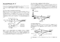
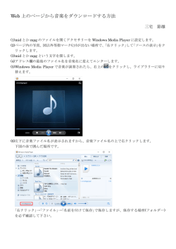
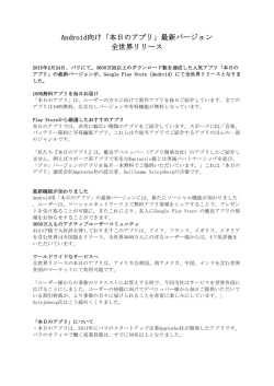
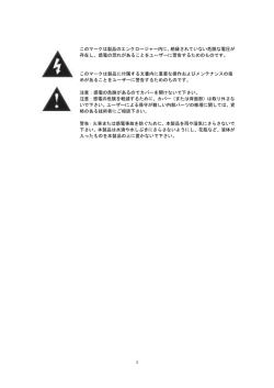
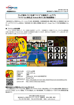
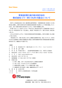
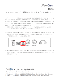
SK-500
NOV. 2000
SPECIFICATIONS
主な仕様
• SK-500 : Sound Canvas
(General MIDI System / GS Format)
● SK-500: サウンド・キャンバス
(GM システム /GS フォーマット対応)
• Number of parts
32
• Maximum Polyphony
64 (voices)
• Internal Sounds
TABLE OF CONTENTS
SPECIFICATIONS .......................................................
LOCATION OF CONTROLS ........................................
EXPLODED VIEW .......................................................
BLOCK DIAGRAM .......................................................
PARTS LIST.................................................................
IDENTIFYING THE VERSION NUMBER ....................
UPDATING SYSTEM SOFTWARE ..............................
TEST MODE ................................................................
目次
Page
主な仕様 ................................................................................ 1
パネル配置図 ....................................................................... 2
分解図 .................................................................................... 3
ブロック図 ........................................................................... 4
パーツリスト ....................................................................... 5
バージョンナンバーの確認方法 .................................. 6
システムのアップデートの方法 .................................. 6
テストモード ....................................................................... 7
Sound Maps:
4 (SC-8820, SC-88Pro,
SC-88, SC-55)
Preset Sounds: 1608
Drum sound sets: 63
User sounds: --User drum sound sets: ---
• Effects
Reverb (8 types)
Chorus (8 types)
Delay (10 types)
2 Band Equalizer
Insertion Effect (64 types)
• Keyboard
49 keys
• Display
7 segments 3 digits LED
• Connectors
USB connector
Serial connector
MIDI OUT connector
Audio Input jack (Stereo miniature phone type)
Audio Output jack (Stereo miniature phone type)
Headphones jack x 2 (Stereo
miniature phone type)
Pedal jack
• Power Supply
DC 9 V (AC Adaptor)
• Power Consumption
500 mA
• Dimensions
844 (W) x 210 (D) x 73 (H) mm
33-1/4 (W) x 8-5/16 (D) x
2-7/8 (H) inches
• Weight (excluding AC
Adaptor)
2.8 kg
6 lbs 3 oz
• Accessories
Owner's Manual English
(#71785801)
AC Adaptor
ACI-120C (#00905756)
ACI-230C (#01018312)
PSB-1U (#01901578)
AC Cord Set 230 VE 1.0 m for
PSB-1U AC Adaptor
(#01903356)
パート数
最大同時発音数
内蔵音色
32
64 音(ボイス)
音色マップ:
MINI JACK STEREO <-->
RCA PIN JACK x2
(#02568289)
MINI JACK STEREO <-->
MINI JACK STEREO
(#02568290)
Pedal Switch DP-2 (#********)
• Options
Computer Cable: RSC-15AT
(for PC-AT Compatible)
RSC-15APL
(for Apple Macintosh)
Pedal Switch: DP-2, DP-6
Expression Pedal: EV-5
* In the interest of product
improvement,the specifications
and/or appearance of this unit
are subject to change without
prior notice.
ドラム音色セット:63
ユーザー音色数 :なし
なし
エフェクト
リバーブ(8 種類)
コーラス(8 種類)
ディレイ(10 種類)
2 バンド・イコライザー
インサーション・エフェクト
(64 種類)
鍵盤
標準鍵盤 49 鍵
(タッチセンス付き)
ディスプレイ
7 セグメント 3 桁 LED
接続端子
USB コネクター
シリアル・コネクター
MIDI OUT コネクター
インプット・ジャック
(ステレオ・ミニ・タイプ)
アウトプット・ジャック
(ステレオ・ミニ・タイプ)
ヘッドホン・ジャック× 2
(ステレオ・ミニ・タイプ)
ペダル・ジャック
電源
消費電流
最大外形寸法
DC 9 V(AC アダプター)
500 mA
844(幅)x 210(奥行)x
73(高さ)mm
質量
2.8 kg(AC アダプター除く)
17059065
Printed in Japan A000 (CM)
MIDI ケーブル(#********)
USB ケーブル (#02239578)
MINI JACK STEREO <-->
RCA PIN JACK x2 (#02568289)
ユーザー・ドラム音色セット:
Audio Cables
CD-ROM (#********)
オーディオ・ケーブル
EURO Converter Plug
ECP01-5A for 230 VE
(#00905234)
USB Cable (#02239578)
AC アダプター ACI-100C
(#00905756)
SC-88, SC-55)
プリセット音色数:1608
MIDI Cable (#********)
取扱説明書 和文 (#71785712)
4 (SC-8820, SC-88Pro,
AC Cord Set 240 VA 1.0 m for
PSB-1U AC Adaptor
(#01903367)
CD-ROM (#********)
付属品
MINI JACK STEREO <-->
MINI JACK STEREO (#02568290)
ペダル・スイッチ DP-2
(#********)
保証書 (#40348001)
別売品
コンピューター・ケーブル
RSC-15N
(NEC 9801 シリーズ用)
RSC-15AT(PC-AT 互換機用)
RSC-15APL
(Apple Macintosh 用)
MIDI ケーブル
MSC-15(1.5 m)
MSC-25(2.5 m)
MSC-50(5.0 m)
ペダル・スイッチ
DP-2
DP-6
フット・ペダル
EV-5
※ 製品の仕様、および外観は、
改良のため予告なく変更する
ことがあります。
SK-500
NOV. 2000
LOCATION OF CONTROLS/
/ パネル配置図
2
1
5
3
4
No.
2
Part Code
Part Name
Q'ty
1
02457345
KEYTOP for SERVICE
3
2
02457356
POWER BUTTON for SERVICE
1
3
02457367
SLIDER KNOB for SERVICE
1
4
02457334
WHEELS ASSY
1
5
02457390
EXT.PARTS SET for SERVICE
1
NOV. 2000
SK-500
EXPLODED VIEW/
/ 分解図
[Parts]
No.
Part Code
Part Name
Q'ty
1
02457390
EXT.PARTS SET for SERVICE
1
2
02457301
MAINBOARD ASSY for SERVICE (EXG)
1
3
02457312
PANELBOARD ASSY for SERVICE (W/WIRING)
1
[Screws]
No.
Part Code
Part Name
Q'ty
A
40011301
SCREW 3x6 BINDING TAPTITE P FE BZC
11
B
40011323
SCREW 3x10 BINDING TAPTITE P BZC
20
3
SK-500
5
6
7
JK2
M34051
14
15
4
2
5
2
19
20
21
22
23
24
25
26
Keyboard
1
(Sub-System)
USB
IC2
JK1
PC
iMac
IC9
IC5
IC16
CN4
1
MIDI
3
2
1
4
M37640E
4
USB
20
4M-DRAM
16M-Flash
(WORK)
(Program)
KeyScan
SSC1080
24MHz
16
11
8bit
X4
SW4A
D +5
16bit
8bit
IC4
IC3
(EFX)
CN3
2
4
1
X2
24.576MHz
IC14
RA09-002
D/A
176P-QFP
PCM1716
DAout
13
13
12
8bit
8bit
4M-DRAM
4M-DRAM
(DelayLine)
(DelayLine)
11
12
A
Pitch
8bit
MB87837
D +5
11
WHEELS
UNIT
16bit
1
IC1
A
D +5
16bit
SH7016
(64kB-MASK)
2
4
3
1
Pedal
X3
CPU
4
15
14
13
12
7.000MHz
I/F Select Switch
A
Data
CN7
CN8
dp
13
a
f g b
c
1
1
2
11
A
2
SW
1
22
IC34
A
Mask-ROM
64Mbit
(WAVE)
IC8
A
Phones1
JK8
Volume
2
SW
DC-IN 9V
IC35
Q
A
2
1
3
1
DC/DC
2
D
2
3
1
AMP
IC20
SW1A
JK7
PANEL BOARD
P
IC7
2
3
1
AMP
SW
128Mbit
(WAVE)
IC10
21
d
e
12
7SEG-LED
Mask-ROM
23
IC11
N
BP5220
C54
102B
JK9
R
IC31
S
2
3
1
Input
JK11
AMP
A
IC32
C57
222B
D
IC21
D +5
DC/DC
NJM2360AM
D
2
3
1
AMP
DAout
D +5 5V/1A
D
Phones2
CN9
LPF
4
18
256k-SRAM
M
U
17
IC12
L
T
16
RS422
Driver
Entry
O
13
(forMac)
D
JK13
K
12
1MHz
20
30
MIDI-OUT
H
J
11
JK5
(USB/PC/Mac/MIDI)
I
10
IC17
Serial
I/F
PC
Mac
E
G
9
BLOCK DIAGRAM/
/ ブロック図
D
F
8
1
C
4
10
B
3
7
8
5
2
4
1
3
6
10
A
2
3
1
5 2 4
1
NOV. 2000
IC33
A
Output
JK10
A
A -5
27
28
NOV. 2000
SK-500
PARTS LIST/
/ パーツリスト
ACCESSORIES (STANDARD) / 標準付属品
SAFETY PRECAUTIONS:
The parts marked
have safety-related characteristics. Use only listed parts for replacement.
QTY
PART NUMBER
DESCRIPTION
MODEL NUMBER
Ex.
10
22575241
Sharp Key
C-20/50
15
2247017300
Knob (orange)
DAC-15D
Failure to completery fill the above items with correct number and description will result in delayed or
even undelivered replacement.
SAFETY PRECAUTIONS:
The parts marked
have
safety-related characteristics.
Use only listed parts for
replacement.
#
71785712
OWNER'S MANUAL
JAPANESE
#
71785801
OWNER'S MANUAL
ENGLISH (Inc. FRENCH/GERMANY/ITALY/SPAIN)
1
1
00905756
AC ADAPTOR
ACI-100C
1
00905767
AC ADAPTOR
ACI-120C
1
01018312
AC ADAPTOR
ACI-230C
1
01901578
AC ADAPTOR
PSB-1U UNIVERSAL
Note: 'AC ADAPTOR PSB-1U UNIVERSAL' does not includes the following AC Cord Set.
Please order these parts independently.
)
10
15
22575241
2247017300
Sharp key
Knob (orange)
注意:補修用 AC ADAPTOR PSB-1U UNIVERSAL は、下記の AC CORD SET を含みません。
C-20/50
DAC-15D
必要な場合は、別途オーダー願います。
01903356
AC CORD SET
230 VE 1.0M for PSB-1U
1
01903367
AC CORD SET
240 VA 1.0M for PSB-1U
1
00905234
EURO CONVERTER PLUG
ECP01-5A (PLUG for 230 VE)
1
#
********
DRIVER CD ROM
JAPANESE
1
#
********
DRIVER CD ROM
ENGLISH
1
********
MIDI CABLE 1.8m
DIN 5M TO DIN 5M
1
NOTE:The parts marked # are new (initial parts)
#
DSB ---> DSP BOARD
JB
---> JACK BOARD
MSB ---> MEMORY SWITCH BOARD
IJB ---> INPUT JACK BOARD
PB
--> POWER BOARD
PS1B --> PS1 BOARD
#
CASING / ケース
#
02457390
Q'ty
EXT.PARTS SET for SERVICE
1
02239578
USB CONNECT CORD 2m
YAF11-0791
1
#
02568289
AUDIO CABLE
MINI JACK STEREO <--> RCA PIN JACK x2
1
#
02568290
AUDIO CABLE
MINI JACK STEREO <--> MINI JACK STEREO
1
"EXT.PART SET" includes the following parts
********
PEDAL SWITCH
DP-2
1
補修用 EXT.PART SET は、以下のパーツを含みます。
TOP CASE
********
40348001
保証書
(JAPAN ONLY)
1
********
********
1
BOTTOM CASE
1
KEYBOARD ASSY CSK49-1
1
KNOB, BUTTON / つまみ、ボタン
#
02457345
KEYTOP for SERVICE
3
#
02457356
POWER BUTTON for SERVICE
1
#
02457367
SLIDER KNOB for SERVICE
1
Bender Unit / ベンダーユニット
#
02457334
WHEELS ASSY
1
PWB ASSY / 基板完成品
# E 02457301
MAIN BOARD ASSY for SERVICE (EXG)
1
#
PANEL BOARD ASSY for SERVICE (W/WIRING)
1
40011301
SCREW 3x6
BINDING TAPTITE P FE BZC
1
40011323
SCREW 3x10
BINDING TAPTITE P BZC
1
02457312
SCREW / ねじ類
PACKING / 梱包材
#
02457289
PAD ACCESSORY BOX for SERVICE
1
#
02457290
PAD ADAPTOR for SERVICE
1
#
02457267
PAD L for SERVICE
1
#
02457278
PAD R for SERVICE
#
02450945
PACKING CASE
JAPANESE
1
#
02450978
PACKING CASE
ENGLISH
1
1
5
SK-500
IDENTIFYING THE VERSION NUMBERS
1. Turn on the power by pressing the [SHIFT] button.
NOV. 2000
バージョンナンバーの確認方法
1. [SHIFT] ボタンを押しながら、本体の電源を入れます。
UPDATING SYSTEM SOFTWARE
システムのアップデートの方法
• Necessary materials
●必要な機材
• SK-500 and AC adaptor
・ SK-500 本体と AC アダプター
• Windows computer (PC98 series cannot be used.)
・ Windows コンピュータ (PC98 シリーズは不可 )
• MIDI sequence software which operates on Windows
・ Windows 上で動作する MIDI シーケンスソフト
• Serial connection cable RSC-15AT (MINI-DIN 8-pin/D-sub 9-pin)
・ シリアル接続ケーブル
• Update CD-ROM for upgrading versions (#17041019)
・ アップデート用 CD-ROM (P/No.17041019)
• They contain memory erase data and data (SK500_**.MID) divided
・ メモリ消去用データ (ERASE.MID) と 32 の SMF データに分割された
into 32 SMF data.
データ (SK500_**.MID) が入っています。
−
The "PLAY" indicator comes on.
"PLAY" のインジケータが点灯します。
Within five seconds after power-on, press the [SHIFT] button once
again and the [PLAY (+)] button in this order.
電源を入れてから 5 秒以内に [SHIFT] ボタンを 1 回と、[PLAY (+)]
ボタンの順に押します。
2. The "USB" indicator comes on.
The numeral displayed at this time is the ROM version number of the
CPU.
2. "USB" のインジケータが点灯します。
この時に表示される数字が CPU の ROM バージョンナンバーです。
−
Disk #1
ERASE.MID
SK500_00.MID
SK500_01.MID
SK500_02.MID
SK500_03.MID
SK500_04.MID
SK500_05.MID
SK500_06.MID
SK500_07.MID
SK500_08.MID
SK500_09.MID
SK500_10.MID
SK500_11.MID
SK500_12.MID
SK500_13.MID
SK500_14.MID
SK500_15.MID
Disk #2
SK500_16.MID
SK500_17.MID
SK500_18.MID
SK500_19.MID
SK500_20.MID
SK500_21.MID
SK500_22.MID
SK500_23.MID
SK500_24.MID
SK500_25.MID
SK500_26.MID
SK500_27.MID
SK500_28.MID
SK500_29.MID
SK500_30.MID
SK500_31.MID
• Settings
1. Set the changeover switch on the rear of the SK-500 CPU to "PC."
2. Connect the serial port of a Windows computer and the SK-500 serial
terminal using the serial connection cable.
Version 1.00 is displayed like this.
バージョン 1.00 は、このように表示されます。
3. After booting the computer, copy all files contained on the update
data disk to the appropriate working directory on the computer is hard
3. Pressing the [PLAY (+)] button turns on the "FUNCTION" indicator.
3. [PLAY (+)] ボタンを押すと "FUNCTION" のインジケータが点灯しま
disk.
Disk #1
ERASE.MID
SK500_00.MID
SK500_01.MID
SK500_02.MID
SK500_03.MID
SK500_04.MID
SK500_05.MID
SK500_06.MID
SK500_07.MID
SK500_08.MID
SK500_09.MID
SK500_10.MID
SK500_11.MID
SK500_12.MID
SK500_13.MID
SK500_14.MID
SK500_15.MID
Disk #2
SK500_16.MID
SK500_17.MID
SK500_18.MID
SK500_19.MID
SK500_20.MID
SK500_21.MID
SK500_22.MID
SK500_23.MID
SK500_24.MID
SK500_25.MID
SK500_26.MID
SK500_27.MID
SK500_28.MID
SK500_29.MID
SK500_30.MID
SK500_31.MID
●機材の設定について
1. SK-500 本体背面の切り替えスイッチを、"PC" 側に合わせます。
2. Windows コンピュータのシリアルポートと SK-500 の SERIAL 端子
をシリアル接続ケーブルで接続します。
3. コンピュータを起動した後、アップデート用データディスクに含ま
れる全てのファイルをコンピュータのハードディスク上の適当な作
業用ディレクトリにコピーしてください。
The numeral displayed at this time is the ROM version number of the
す。この時に表示される数字がプログラムの ROM バージョンナン
4. Start the computer's sequence software.
4. コンピュータのシーケンスソフトを起動します。
program.
バーです。
5. Open the properties of Start -> Setting -> Control Panel -> Multimedia
5. スタート→設定→コントロールパネル→マルチメディアのプロパ
in this order and set the MIDI output (single equipment) settings to
Roland Serial MIDI Out A from the MIDI tab.
6. As occasion demands, also set the MIDI port settings of the MIDI
sequence software to Roland Serial MIDI Out A in the same manner.
Version 1.01 is displayed like this.
4. Pressing the [PLAY (+)] button turns on the "PLAY" indicator.
The numeral displayed at this time is the ROM version number of the
USB controller.
バージョン 1.01 は、このように表示されます。
4. [PLAY (+)] ボタンを押すと "PLAY" インジケータが点灯します。
この時に表示される数字が USB コントローラの ROM バージョンナン
バーです。
Caution:
About 15 minutes are required to send all update data from the
sequencer.
ティを開き、MIDI のタブから MIDI 出力 ( 単一の機器 ) の設定を
Roland Serial MIDI Out A にします。
6. 必要に応じて MIDI シーケンスソフトの MIDI ポート設定も同様に
Roland Serial MIDI Out A に合わせます。
注意 :
シーケンサから全ての更新データを送るのに 15 分ほどかかります。
So, it is recommended that the computer be reset in advance.
アップデート作業中のコンピュータにおいて以下の状態が発生すると、
エラーが発生し易くなるのであらかじめ解除しておくことを推奨しま
す。
1. The power saving mode is entered by the power management
1. 電源管理機能によって省電力モードになること。
If the following states occur in the computer being updated, an error
will occurs.
function.
2. The screen saver moves.
2. スクリーンセーバが動くこと。
3. アップデート作業中に別のアプリケーションを動かすこと。
3. Another application is operated while updating is in progress.
• Operating Procedure
1. Turn on the power switch of the SK-500 by pressing the [SHIFT] butVersion 1.00 is displayed like this.
When you have checked each version number, turn off the power.
バージョン 1.00 は、このように表示されます。
1. [SHIFT] ボタンを押しながら、本体の電源スイッチを入れます。
ton.
バージョンナンバーの確認が完了しましたら、本体の電源を切ってく
ださい。
The "PLAY" indicator comes on.
2. Within five seconds after power-on, press the [SHIFT] button three
6
●アップデート方法
"PLAY" インジケータが点灯します。
2. 電源を入れてから 5 秒以内に [SHIFT] ボタンを 3 回と [PLAY
times and the [PLAY (+)] button in this order.
(+)] ボタンの順に押します。
The LED displays "U" and the program memory enters the initialization
LED は "U" を表示してプログラムメモリの初期化待機状態になりま
wait state.
す。
NOV. 2000
3. After opening the (erase.mid) file on the computer, close it.
SK-500
3. コンピュータで (erase.mid) ファイルをプレイ後、停止させます。
The LED displays "E" and erasing of the program memory starts.
LED は "E" を表示して、プログラムメモリの消去が始まります。
Fifteen minutes are required to erase it.
消去には約 15 秒かかります。
4. After erasure is completed, "r" is displayed.
When this state is entered, new data can be sent.
5. Continuously play 32 update SMF data items in the order of file numbers.
ER (Error) 3: Memory write failed.
ER3: メモリの書き込みに失敗しました。
ER (Error) 4: An error was detected in the checksum of received data.
ER4: 受信データのチェックサムで誤りが検出されました。
ER (Error) 5: An error occurred in serial communication.
ER5: シリアル通信でエラーが発生しました。
4. 消去完了後に "r" が表示されます。
この状態になれば新しいデータを送ることができます。
5. 32 個のアップデート用 SMF データをファイルの番号順に連続して
プレイさせます。
TEST MODE
テストモード
• Necessary materials
●必要な機材
• SK-500 and AC adaptor
・ SK-500 本体と AC アダプター
• Computer Test Cable (P/No.17049906)
・ PC テストケーブル (P/No.17049906)
• Pedal DP-2/6
・ ペダル (DP-2/6)
• Headphones or Monitor Speaker, Speaker connection cable
・ ヘッドホンまたは、モニタースピーカーと接続ケーブル
Note:
This test mode does not include the USB and MIDI operation
tests.
While data are being received, "r" finely blinks on the LED in the col-
データ受信中は左の桁の LED の "r" が細かく点滅します。
umn on the left.
6. When all data have been sent, "Fin" is displayed.
6. 全てのデータの送信が完了すると "Fin" の表示が出ます。
7. This completes updating.
7. 以上でアップデート作業は完了です。
Turn on the power of the SK-500 again to check its operation.
• Error Display while Updating
●アップデート作業中のエラー表示について
アップデートのデータ送信中あるいは送信完了後にエラーメッセージが
表示される場合があります。
Since each message indicates the state in which updating failed, redo it
from the beginning.
いずれもアップデートが失敗した状態ですので、最初からやり直してく
ださい。
• How to Enter the Test Mode
●テストモードに入る方法
1. Set the changeover switch on the rear of the SK500 to "Mac".
1. 本体背面の切り替えスイッチを "Mac" 側に設定しま
す。
2. Turn on the power switch of the SK-500 by pressing the [SHIFT] button.
2. [SHIFT] ボタンを押しながら、本体の電源スイッチ
を入れます。
If the position of the changeover switch is set to other than "Mac", all
LEDs come on and go off repeatedly.
この時切り替えスイッチのポジションが "Mac" 側以外になっている
と、LED は全点灯と消灯を繰り返します。
At that time, reset the position to "Mac".
その時は、"Mac" 側に設定し直してください。
3. The LED of the "PLAY" indicator comes on.
ER (Error) 2: Memory erase failed.
通常の使用状態で接続して動作確認を行ってください。
Connect the USB and MIDI cables in the normal operating state to
check each operation.
本体の電源を再度入れて直して、本体の動作確認を行ってください。
While update data are being sent or after completion of sending, error
messages may be displayed.
ER (Error) 1: Memory was not recognized correctly.
注意:
本テストモードには USB と MIDI の動作テストは含まれません。
3. "PLAY" インジケータの LED が点灯します。
ER1: メモリが正しく認識されませんでした。
ER2: メモリの消去に失敗しました。
Subsequently, within five seconds :
続いて 5 秒以内に、
1. Press the [SHIFT] button twice.
1.[SHIFT] ボタンを 2 回押します。
2. The [PLAY (+)] button once.
2.[PLAY (+)] ボタンを 1 回押します。
4. Immediately after the SK-500 enters the test
mode, the CPU version number is displayed.
The "USB" indicator comes on.
4. テストモードに入った直後は、CPU バージョンが表示
されます。
"USB" のインジケータが点灯します。
7
SK-500
NOV. 2000
The numeral displayed at this time is the ROM version number of the
CPU.
Version 1.00 is displayed like this.
この時に表示される数字が CPU の ROM バージョンナンバーです。
バージョン 1.00 の場合は、このように表示されます。
5. Pressing the [PLAY (+)] button turns on the
"FUNCTION" indicator.
The numeral displayed at this time is the ROM version number of the
program.
Version 1.01 is displayed like this.
5. [PLAY (+)] ボタンを押すと "FUNCTION" のインジ
ケータが点灯します。
8. LED Test
[PLAY (+)] ボタンを押すと LED のテストに入ります。
Pressing the [SHIFT] button from this display turns on all LED segments
sequentially.
この表示から [SHIFT] ボタンを押すと LED 全てのセグメントが 1 つづ
つ点灯していきます。
When this step is terminated, each of the "USB", "FUNCTION" and
"PLAY" indicators blink.
終了すると "USB" "FUNCTION" "PLAY" の各インジケータが点滅します。
Even if the error is displayed, you can proceed to the next test by simultaneously pressing the [FUNCTION (-)] and [PLAY (+)] buttons.
全てのチェックが完了しなくても [FUNCTION (-)] ボタンと [PLAY
(+)] ボタンを同時に押すと次のテストに進むことが出来ます。
この時に表示される数字がプログラムの ROM バージョンナンバーで
す。
バージョン 1.01 の場合は、このように表示されます。
9. Switch/Wheel/Pedal Test
Pressing the [PLAY (+)] button enters the operation function test.
6. Pressing the [PLAY (+)] button turns on the
"PLAY" indicator.
The numeral displayed at this time is the ROM version number of the
USB controller.
6. [PLAY (+)] ボタンを押すと "PLAY" インジケータが
点灯します。
The first display is as follows:
The LED corresponding to each operation comes on.
1. Press the [SHIFT] button.
バージョン 1.00 の場合は、このように表示されます。
2. Press the [FUNCTON (-)] button.
3. Press the [PLAY (+)] button.
4. Operate the PITCH wheel fully up and down.
7. デバイステスト
7. Device Test
5. Operate the DATA ENTRY wheel fully up and down.
Pressing the [PLAY (+)] button performs device self diagnosis.
[PLAY (+)] ボタンを押すとデバイスの自己診断を行います。
If all the devices operate normally, "d" is displayed and each of the
"USB", "FUNCTION" and "PLAY" indicators blink.
全て正常に動作していれば "d" が表示され、"USB" "FUNCTION"
"PLAY" の各インジケータが点滅します。
If there is a device which is not operating, the following error is displayed.
もし正常に動作していないデバイスがあれば以下のようなエラー表示
になります。
1: Flash ROM (IC5)
2: XP Chip (IC3)
3: XP DRAM (IC10)
4: LSP Chip (IC4)
6. Connect the wheel pedal to the PEDAL jack to turn the power on/off.
When all checks are OK, "H" is displayed and each of the "USB", "FUNCTION" and "PLAY" indicators blink.
Even if you have not completed all checks, you can proceed to the next
step by simultaneously pressing the [FUNCTION (-)] and [PLAY (+)] buttons.
10. Serial Interface Test
Pressing the [PLAY (+)] button enters the serial interface test.
5: LSP DRAM (IC11)
6: Wave ROM1 (IC7)
Even if the error is displayed, you can proceed to the next test by
simultaneously pressing the [FUNCTION (-)] and [PLAY (+)] buttons.
8
9. スイッチ / ホイール / ペダルテスト
[PLAY (+)] ボタンを押すと操作機能のテストに入ります。
最初の表示は以下のようになっています。
この時に表示される数字が USB コントローラの ROM バージョンナン
バーです。
Execute the following operations (the order of execution is optional).
Version 1.00 is displayed like this.
8. LED テスト
Pressing the [PLAY (+)] button enters the LED test.
7: Wave ROM2 (IC8)
8: USB (IC2)
エラーが表示された場合でも、[FUNCTION (-)] ボタンと [PLAY (+)]
ボタンを同時に押すと次のテストに進むことが出来ます。
以下の操作を実行してください。( 実行順は任意 )
各操作に対応して LED が消灯していきます。
1.[SHIFT] ボタンを押す。
2.[FUNCTION(-)] ボタンを押す。
3.[PLAY(+)] ボタンを押す。
4.PITCH ホイールを上下いっぱいに操作する。
5.DATA ENTRY ホイールを上下いっぱいに操作する。
6.PEDAL ジャックにホールドペダルを接続して ON/OFF する。
全てのチェックが OK なら "H" が表示され "USB" "FUNCTION" "PLAY"
の各インジケータが点滅します。
全てのチェックが完了しなくても [FUNCTION (-)] ボタンと [PLAY
(+)] ボタンを同時に押すと次のテストに進むことが出来ます。
10.シリアルインターフェイステスト
10.シリアルインターフェイステスト
[PLAY (+)] ボタンを押すとシリアルインターフェイスのテストに入り
ます。
NOV. 2000
SK-500
1. The display changes in accordance with the position of the
changeover switch on the rear (initially, "P3" might have been dis-
1. リアの切り替えスイッチのポジションに応じて表示が変わります。
( 最初は "P3" が表示されているはずです )
played).
Even if you have not completed all checks, you can proceed to the
全てのチェックが完了しなくても [FUNCTION (-)] ボタンと [PLAY
next step by simultaneously pressing the [FUNCTION (-)] and
(+)] ボタンを同時に押すと次のテストに進むことが出来ます。
[PLAY (+)] buttons.
1: USB
2: PC
2. Then, the serial input/output check is performed.
3: Mac
4: MIDI
12. Effect Test
12.エフェクトテスト
12.エフェクトテスト
Pressing the [PLAY (+)] button enters the effect test.
[PLAY (+)] ボタンを押すとエフェクトテストに入ります。
Use speakers and headphones to check the effect.
発音を確認するためにスピーカまたはヘッドホンを使用してくださ
い。
1. Insertion Effect (Delay)
1. インサーションエフェクト ( ディレイ )
2. 次にシリアル入出力のチェックを行います。
Connect the serial check jig to the serial terminal.
シリアルチェック治具を、シリアル端子に接続してください。
If correct operation is performed, "o" is displayed in the column on the
正しく動作していれば右側の桁に "o" が表示されます。
right.
また "USB" "FUNCTION" "PLAY" の各インジケータが点滅します。
Also, each of the "USB", "FUNCTION" and "PLAY" indicators blink.
Even if you have not completed all checks, you can proceed to the
全てのチェックが完了しなくても [FUNCTION (-)] ボタンと [PLAY
next step by simultaneously pressing the [FUNCTION (-)] and [PLAY
(+)] ボタンを同時に押すと次のテストに進むことが出来ます。
Pressing the [SHIFT] button enables you to hear a snare drum
[SHIFT] ボタンを押すとスネアドラムの音が聞こえます。
sound.
初めの発音から 1.5 秒後に鳴るのがディレイ音です。( 発音は繰
A delayed sound is heard 1.5 seconds later (the sound is repeated).
り返されます )
Check the sound volume and quality.
音量と音質をチェックしてください。
(+)] buttons.
2. System Effect (Delay)
11. Sound Test
11.サウンドテスト
11.サウンドテスト
Pressing the [PLAY (+)] button enters the sound test.
[PLAY (+)] ボタンを押すとサウンドテストに入ります。
Use speakers or headphones to check the sound.
発音を確認するためにスピーカまたはヘッドホンを使用してくださ
2.システムエフェクト ( ディレイ )
Pressing the [SHIFT] button enables you to hear a castanets sound.
[SHIFT] ボタンを押すとカスタネットの音が聞こえます。
A delayed sound is heard 1.5 seconds later (the sound is repeated).
初めの発音から 1.5 秒後に鳴るのがディレイ音です。( 発音は繰
Check the sound volume and quality.
り返されます ) 音量と音質をチェックしてください。
い。
3. System Effect (Reverbrator)
1. Pressing the [SHIFT] button enables you to hear a sine wave only from
1. [SHIFT] ボタンを押すと左 (L) チャンネルだけからサイン波が聞こ
[SHIFT] ボタンを押すと深いリバーブがかかったスネアドラムの音
sound with deep reverberation.
が聞こえます。( 発音は繰り返されます )
音量と音質をチェックしてください。
the left (L) channel.
えます。
A delayed sound is heard 1.5 seconds later (the sound is repeated).
Check the sound volume and quality.
音量と音質をチェックしてください。
Check the sound volume and quality.
2. Then, pressing the [SHIFT] button enables you to hear a sine wave
2. 次に、[SHIFT] ボタンを押すと右 (R) チャンネルだけからサイン波
only from the right (R) channel.
が聞こえます。
Check the sound volume and quality.
音量と音質をチェックしてください。
3. Subsequently, pressing the [SHIFT] button enables you to hear sine
3. システムエフェクト ( リバーブ )
Pressing the [SHIFT] button enables you to hear a snare drum
This completes all the tests.
以上で全てのテストが終了です。
Turn off the power of the SK-500.
本体の電源を切って下さい。
3. さらに、[SHIFT] ボタンを押すと左右 (L/R) 両チャンネルからサイ
waves from both the left and right (L/R) channels.
ン波が聞こえます。
Check the sound volume and quality.
音量と音質をチェックしてください。
When you proceed to this step, each of the "USB", "FUNCTION" and
ここまで進むと "USB" "FUNCTION" "PLAY" の各インジケータが点滅
"PLAY" indicators blink.
します。
9
© Copyright 2026 Paperzz