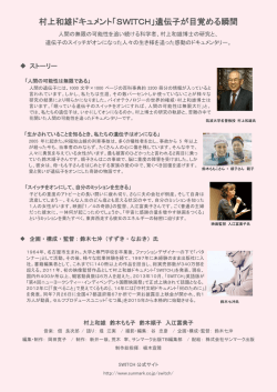
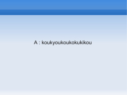
形
D4BL
電磁ロック・セーフティドアスイッチ
取 扱 説 明 書
オムロン製品をお買い上げいただきありがとうございます。
この製品を安全に正しく使用していただくために、お使い
になる前にこの取扱説明書をお読みになり、十分にご理解
してください。
お読みになった後も、いつも手元においてご使用ください。
・スイッチ本体については、埃や水などの浸入から保護されていますが、ヘッド
部の操作キー挿入口へは異物が入らないようにしてください。早期摩耗、破損
などの原因になります。
・スイッチ機能が十分に発揮されないことがあります。製品を落下させないでく
ださい。正常動作を損なう恐れがありますので、いかなる場合でも製品の分解・
改造は行わないでください。
●リリースキーについて
・停電時あるいは緊急時にロックを解除
する場合に用います。
リリースキーを用いて、LOCK位置からU
NLOCK位置にするとロックが解除
リリースキー
して安全扉などを開けることができま
す。
(メカニカルロックタイプのみ)
・UNLOCK位置の状態では、大型マシン・踏み込み型マシンなど内での予備
調整作業中にドアが閉じても、ロックがかからずマシンも起動しません。
・このリリースキーを、マシンの停止始動用に使用しないでください。
・補助ロック解除は責任者のみが行ってください。
・不特定な人による容易なリリースキーによるロック解除を避けるため、リリー
スキーはLOCK 状態にして、シールワックス(ろう付け)などを施し、封印して
ください。リリースキーの操作後は、スイッチの操作を再開する前に、その封
印を復旧してください。
・本体にカバーを取り付ける際には、必ず鍵位置はLOCK状態であることを確
認して組み込んでください。
●ストッパーの設置について
本体をストッパーとして使用しないでください。
操作キーのツバがヘッド部に当たらないように、下図に示すように必ずストッパーを設置
してください。
本体に耐久衝撃1000m/s2 を超える衝撃を加えないでください。
●ソレノイドロックタイプについて
ソレノイドロックタイプは、ソレノイド通電時しかロックがかかりませんので、急な停電
などにより、ソレノイドへの通電がなくなると、ロックが解除となります。従って機械停
止後も扉内部が危険状態を持続するような機械にはソレノイドタイプは使用できません。
E C 適 合 宣 言
オムロンは、形 D4BL が以下の EC 指令要求に適合していることを宣言します。
機械指令
2006/42/EC
安 全 上 の ご 注 意
●警告表示の意味
注意
誤った取り扱いをすると、傷害を負う可能性が想定さ
れる場合、および物的損害の発生が想定される場合を
示します。
●警告表示
●警告表示
注
意
扉が開いた状態で操作キーを入れないでください。
また、衝撃吸収用ダンパー(出荷時据付)を用いて、
動作させないでください。
機械が動作し、傷害の恐れがあります。
お
願
い
・電源を入れた状態で分解したり、内部に触ったりしないでください。
感電の恐れがあります。
・操作キーはドア開閉時に身体へ接触しない箇所へ取付けてください。
傷害の恐れがあります。
・非常停止回路や人身事故につながる安全回路のスイッチとして使用する場合、直接
開路動作機構を有するNC接点側を使用し、ポジティブモードで動作するよう設定
してください。また、安全のために、スイッチ及び操作キーが安易に取外しできな
いよう一方向回転ねじあるいはそれと同等の手段によって取付けてください。
または、防護カバーや警告表示をつけてください。
・回路の短絡によるスイッチの破損を防ぐため、定格電流の 1.5~2 倍の遮断電流値
のヒューズをスイッチと直列に接続してください。EN認定定格でご使用の場合
は、IEC60269 適合の10A ヒューズ形gI あるいは形gGをご使用ください。
・配線作業時は通電しないでください。
・爆発性ガス、引火性ガスなどの雰囲気中では使用しないでください。
・負荷電流は必ず、定格値以下でご使用ください。
・各端子への誤配線は絶対にしないでください。
・取付調整後は必ず動作確認を実施してください。
・ロック強度を超える力がスイッチに加わった場合、スイッチが破壊し、設備が動作
し続ける恐れがあります。
±0.3 ㎜以内に納めてくださ
い。(位置ズレ等により早期摩
耗、破損等の原因となります。)
・形D4BLとD4BSの操作キ
ーは共用不可です。
●ヘッドの方向変換について
・スイッチ本体との合わせ面の所で、
図(A)または(B)に示すようにヘ
ッド部を 45°回転させた状態で取
付け、取外しができます。
また、方向を変換する時も 45°回
転した状態で図に示す回転レバー
の凸部をプランジャの凹部溝に合
わせてから、
右あるいは左回転させ ヘッド部側下面図 スイッチボディ側上面図
希望するヘッドの方向に設定して
ください。なお、その際にプランジ
ャの凹部が回転レバーの下(内蔵ス
イッチ側)に位置していることをご
回転レバー
操作プランジャ
および凸部
および凹部溝
確認願います。(45°回転状態でヘ
groove mechanism
ッドの方向を設定しない場合、
プラ 正常な位置関係
ンジャの凹部が回転レバーを押し 回転レバー、プランジャ
スイッチボディ
込み、
スイッチが動作しなくなると
同時に、これらの機能部品の損傷・
内蔵スイッチの破損などの原因と
回転レバー
なります。) なお、異物を介在さ
(凸部)
せないようにご注意ください。
操作プランジャ
(凹部溝)
・取付けの際には必ずメカニカルロ
ック/ソレノイドリリース機能チェ
内蔵スイッチ
ックを行ってください。
●扉の固定について
・扉を閉じているとき(操作キー挿入状態)、扉の自重、扉の緩衝用ゴム等により扉(操
作キー)がセットゾーンを越えて押し戻されることがあります。
ロックを解除する際に操作キーに荷重がかかっているとロックが外れない場合があ
ります。
セットゾーン内に納まるように止め金(フック)などで扉を固定してください。
正 し い 使 い 方
0685903-2 M
オムロン株式会社
・操作キーとキー挿入口のズレは
■使用環境について
(1)油水や薬品のかかる環境において事前に影響(適正)をご確認の上、ご使用ください。
油水、薬品の種類によってはシール性劣化により、接触不良、絶縁不良、漏電、焼
損の恐れがあります。
(2)下記の環境では使用しないでください。
・温度変化の激しい場所
・湿度が高く、結露が生じる恐れのある場所
・振動の激しい場所
・直接、加工屑や塵埃のかかる場所
■耐久性について
・スイッチの耐久性は開閉条件により大きく異なります。ご使用にあたっては必ず実
使用条件にて実機確認を行い、性能上問題のない開閉回数内にてご使用ください。
■取付方法
●適正締付トルク
ねじのゆるみは早期故障の原因となりますので、各部の適正締付トルクにて締付
けてください。
本体取付穴
4.90~5.88 N・m
M5 ねじ
カバー締付ねじ
1.18~1.37 N・m
M4 ねじ
コンジットコネクタ
1.77~2.16 N・m
キャップスクリュー
1.27~1.67 N・m
ヘッド締付ねじ
0.78~0.98 N・m
M3.5 ねじ
操作キー取付ねじ
2.35~2.75 N・m
M5 ねじ
端子ねじ
0.59~0.78 N・m
M3 ねじ
●本体・操作キーの取付について
本体・操作キーの取付には、M5ねじを4本用い、座金を使って適正締付トルク
で堅固に取付けてください。
・取付穴 ・本体取付穴加工寸法
・操作キー取付穴加工寸法
2-M5
4-M5
形 D4BL-K1
20±0.1
2-M5
形 D4BL-K2
74±0.1
40±0.1
2-M5
形 D4BL-K3
100±0.1
30±0.1
・当社専用操作キー以外のものは使用しないでください。専用操作キー以外での操作
はスイッチの破損を招くので、装置の安全性のためにも行わないでください。
■配線
●配線について
・ケーブルと導体
推奨接続ケーブル:AWG20~18/ULstyle2464
ケーブルサイズ7芯
・ケーブルむき代
ターミナルNO.
E1
E2
31
12
23(21)
24(22)
Lp(㎜)
30±2
35±2
45±2
55±2
65±2
70±2
90±2
Lv(㎜)
80±2
75±2
60±2
50±2
45±2
35±2
50±2
a(㎜)
8±1
●導体の接続方法
・外被絶縁シース端面が図に示しますよう
にコンジット口内壁面AまたはB面に合
うようにケーブルをコンジットへ挿入し
てください。
・配線の作業性を向上させるため、コンジ
ット口に近い端子から順番に接続してく
ださい。
・導体末端に圧着端子を使用しない場合は、
時計巻きできるように端子の右側に挿入
してください。
・また、適切な絶縁を保つために導体が端子からはみだすことのないよう、導体
を2,3 回捻り確実に挿入し、締付けてください。
●表示灯付きの場合
表示灯は、機械の加工工程の状態を表しています。
色の種類として、橙、緑があります。
橙はソレノイドの通電を示しています。
端子番号E1(+)、E2(-)に並列に接続してください。
緑はドアの開閉を示しています。
メインスイッチに1NC/1NOタイプが使用されている時にはドアが
開いていることを示します。端子番号24、E2(-)に接続してください。
メインスイッチに2NCタイプが使用されているときにはドアが閉じて
いることを示します。端子番号22、E2(-)に接続してください。
表示灯の点灯
項目
動作モード
内蔵スイッチ
1NC/1NO
+1NC
2NC+1NC
2NC+2NC
扉状態
電磁ロック
LED 色(配線)
橙(E1-E2)
緑(24-E2)
LED 色(配線)
橙(E1-E2)
緑(22-E2)
LED 色(配線)
橙(E1-E2)
緑(22-E2)
Ⅰ
開
Ⅱ
閉
Ⅲ
閉
ON
OFF
ON
○
○
×
×
○
×
○
×
×
○
○
○
表示灯の接続はメイン回路、
表示灯を指定の端子番号に
図の様に重ねて取付けてく
ださい。
表示灯回路配線
外部配線
○:点灯
×:消灯
○
×
○
×
○
○
●コンジット口の処理について
IP67 特性保持のため、オムロン製コネクタ形
SC-□Mシリーズをお使いください。
PG13.5コンジットサイズには、日本フレックス社
製形ABS-08PG13.5、形ABS-12PG13.5 をお使い
ください。
・IP67 を確保するため、コネクタのコンジット側にシールテープを巻付けてください。
・ケーブルについては該当コネクタが要求する適正外径でご使用ください。
・配線の際には、使用しない箇所のコンジット口は付属のキャップスクリューを用い、
適正締付トルクで締付けてください。
■その他
・ソレノイドは通電により発熱しますので触れないでください。
■技術仕様
適合:機械指令,EN ISO14119
認定:EN60947-5-1,GS-ET-19, UL508, CSA C22.2 No14, GB14048.5
使用カテゴリー:AC-15
定格電圧:250VAC(表示灯なし)、115VAC(LEDタイプ)、250VAC(ネオンランプタイプ)
定格電流:3A(表示灯なし)、6A(LED タイプ)、3A(ネオンランプタイプ)
直接開路動作ストローク:最小20mm
直接開路動作力:最小 19.61N
全ストローク:最小 23mm
許容操作速度:0.05~0.5m/sec
許容操作頻度:最大 30回/分
短絡保護装置:10A ヒューズタイプgIまたはgG(IEC60269)を使用してください。
ロック強度(Fzh):最小 700N (EN ISO14119)
コード化レベル:低
■保守・修理について
保守・修理の際には設備使用者ご自身での保守、修理は行わず、設備(機械)メーカー
へご連絡(相談)するよう、設備の取扱説明書、マニュアルなどに記載ください。
ご承諾事項
「当社商品」は、一般工業製品向けの汎用品として設計製造されています。従い
まして、次に掲げる用途での使用は意図しておらず、お客様が「当社商品」をこ
れらの用途に使用される際には、
「当社」は「当社商品」に対して一切保証をいた
しません。ただし、次に掲げる用途であっても「当社」の意図した商品用途の
場合や特別の合意がある場合は除きます。
(a) 高い安全性が必要とされる用途(例:原子力制御設備、燃焼設備、航空・
宇宙設備、鉄道設備、昇降設備、娯楽設備、医用機器、安全装置、その他生
命・身体に危険が及びうる用途)
(b) 高い信頼性が必要な用途(例:ガス・水道・電気等の供給システム、24 時
間連続運転システム、決済システムほか権利・財産を取扱う用途など)
(c) 厳しい条件または環境での用途(例:屋外に設置する設備、化学的
汚染を被る設備、電磁的妨害を被る設備、振動・衝撃を受ける設備など)
(d) 「カタログ等」に記載のない条件や環境での用途
*(a)から(d)に記載されている他、「本カタログ等記載の商品」は自動車
(二輪車含む。以下同じ)向けではありません。自動車に搭載する用途には
利用しないで下さい。
自動車搭載用商品については当社営業担当者にご相談
ください。
*上記は適合用途の条件の一部です。
当社のベスト、総合カタログ、データシー
トなど最新版のカタログ、マニュアルに記載の保証・免責事項の内容をよく
読んでご使用ください。
オムロン株式会社 インダストリアルオートメーションビジネスカンパニー
●お問い合わせ先
カスタマサポートセンタ
01200120-919919-066 (フリーコール)
携帯電話・PHS などではご利用いただけませんので、
その場合は下記電話番号へおかけください。
電話 055055-982982-5015 (通話料がかかります)
【技術のお問い合わせ時間】
■営業時間:8:00~21:00
■営業日:365 日
■上記フリーコール以外の FA システム機器の技術窓口:
電話 055055-977977-6389 (通話料がかかります)
【営業のお問い合わせ時間】
■営業時間:9:00~12:00/13:00~17:30 (土・日・祝祭日は休業)
■営業日:土・日・祝祭日/春期・夏期・年末年始休暇を除く
●FAX によるお問い合わせは下記をご利用ください。
カスタマサポートセンタ お客様相談室 FAX 055-982-5051
●その他のお問い合わせ先
納期・価格・修理・サンプル・仕様書は貴社のお取引先、
または貴社担当オムロン営業員にご相談ください。
Model D4BL
Guard Lock Safety-door Switch
Instruction Sheet
Please read all instructions before using to ensure
proper use and application of the switch. Save this
instruction sheet for future reference.
・If the force exceeding holding force is imposed on the operation key,
the lock mechanism may break and the equipment in the machine room
will start operating.
・Though the switch body is protected from the ingress of dust or water,
avoid the ingress of foreign substance through the key hole on the
head. Otherwise, wear in short time or break may be caused.
・Do not drop the switch. Excessive shock and vibration can cause
malfunction or other damage to switch characteristics. Do not
disassemble the internal switch, there are no user serviceable parts
inside.
●Release key
・The release key is used to unlock the switch in case of emergency or
if the power supply to the switch fails.
・In the case of mechanical lock type,
rotate the release key to “Unlock”
from “Lock” so that locking will be
released and the door can be open.
When release key is set to “Unlock”,
the door will not be locked and no
power will be supplied to machine even
if the door is closed.
Release key
The safety of operator working in machine room is ensured.
・Do not use the release key to start or step the machine.
・Only authorized person must use release key.
・To prevent the release key from being used by unauthorized personnel,
set it to LOCK and seal it with sealing wax. After the release key
operation should be restored to its sealed before restart.
・Confirm position of the release key is under “Lock” when assembling
the cover in the main body.
●Stopper
Do not use the switch as a stopper. Be sure to install a stopper as
shown in the following illustration to prevent edge of operation key
from hitting the switch directly.
Do not apply shock over the shock resistance 1000m/s2 on the switch.
0685903-2 M
OMRON Corporation
Original instruction
EC Declaration of Conformity
OMRON declares that D4BL is in conformity with the
requirements of the following EC Directives:
Machinery Directive 2006/42/EC
CAUTION
Not following a precaution given
as a“ Caution” can result in
injury to people or damage to the
product or system.
CAUTION
Do not dismount the operation key from the door intentionally
and insert it to the switch with the door open. Do not operate
with the shock damper, which is installed into the switch head
when the switch is shipped. Machine may start operating and
injury or death may be caused.
NOTICE
・Do not disassemble or touch inside under power-on.
・Install the operation key so that it will not hit the operator when the
door open. Injury may be caused.
・When operating limit switch as a part of a safety circuit or an emergency
stop circuit to prevent injury, operate the NC contacts that have
direct-opening function in positive mode. For safety, tighten the switch
body and operation key with one-way screws or equivalents. Or install a
switch protection cover and warning label for safety to prevent easy removal
of the switch.
・Connect the fuse to the switch in series to prevent it from short circuit
damage. The value of the breaking current of the fuse must be calculated
by multiplying rated current by 150 to 200%. When using the switch with
EN ratings, use 10 A fuse, type gI or gG that complies with IEC60269.
・Do not put the electric power when wiring.
・Do not use the switch where explosive gas, ignitable gas, or any other harmful
gases may be present.
・Keep the electrical load below the rated value.
・Never wire to a wrong terminal.
・Be sure to evaluate the switch under actual working conditions after
installation.
●Solenoid lock type
The solenoid lock type locks the door only when power is supplied
to the solenoid. The door will be unlocked if the power supply to
the solenoid fails. Do not use supplied lock type for machines that
continue to move for a while even after the machine power is off.
■Environment
1.Make sure to the check influence of the environment when using
the switch under the ambient condition of oil and chemicals.
Certain kinds of oil and chemicals may adversely affect sealing
properties, which may cause faulty contacts, faulty insulation,
electric shock hazard or the burning.
2.Do not use the switch under any of the conditions mentioned below.
・Frequent temperature changes.
・High humidity or where dew condensation may be generated.
・Where the switch is subjected to severe vibration.
・Where the processing trash or dust is directly sprayed.
■The durability of the switch is seriously affected by the number
of electrical and mechanical actuations. Evaluate the switch under
actual working conditions before permanent installation. Be sure
to keep the frequency of operations within specifications.
■Mounting
●Tightening torque
Adequate tightening torque are as follows and tighten within the
range.
Switch mounting hole
4.90 to 5.88N・m
M5 screw
Switch cover screw
1.18 to 1.37N・m
M4 screw
Connector at conduit opening
1.77 to 2.16N・m
Cap screw
1.27 to 1.67N・m
Head screw
0.78 to 0.98N・m
M3.5 screw
Operation key mounting hole
2.35 to 2.75N・m
M5 screw
Terminal screw
0.59 to 0.78N・m
M3 screw
●Mounting of the switch and operation key
Four pieces of M5 bolt and spring washer are used for mounting
the switch body.
When operation key mounted, two pieces of M5 bolt are used.
Do not use the operation key other than dedicated Omron’s.
Otherwise switch may be damaged.
Switch mounting hole
Process dimension
4-M5
●Indicators
Lighting of indicators
Condition
Operation mode
Operation key mounting hole
Process dimension
2-M5
Build-in
Type D4BL-K1
20±0.1
74±0.1
2-M5
Type D4BL-K2
40±0.1
2-M5
100±0.1
Example of mounting
switch
1NC/1NO+1NC
Type D4BL-K3
Door condition
solenoid
Indicator/Wiring
Orange/ E1-E2
Green / 24-E2
Ⅰ
Ⅱ
Ⅲ
Open
ON
Closed
OFF
Closed
ON
○
○
×
×
○
×
○
×
×
○
○
○
Indicator/Wiring
30±0.1
2NC+1NC
Orange/ E1-E2
Green / 22-E2
Indicator/Wiring
2NC+2NC
Orange/ E1-E2
○
×
○
Green / 22-E2
×
○
○
●Mounting of operation key
Note
:
○
……
Lighted
・Operation key must be mounted onto the
× …… off
door such that it and entrance of
Indicators must be wired to designated terminals with main circuit as illustration.
switch head may match each other with
the tolerance of ±0.3 ㎜.
・Do not use Model D4BS operation key
Indicator
for D4BL. It is not compatible.
Main Circuit
●Head direction change
As shown right in (A) and (B), the head
can be mounted and dismounted by
●Handling of conduit opening
rotating the head by 45゜.
To assure IP67 protection, use the OMRON type SC-□M series for connectors.
To change the direction of the head,
As alternatives for PG13.5 conduit size, type ABS-08PG13.5 or
Head Bottom View
Switch Top View
ABS-12PG13.5 manufactured by NIPPON FLEX may be used.
make sure that the protruding part of
Apply
sealing tape between connector and conduit opening so that the
the rotating lever engages with the
enclosure will conform to IP67.
groove of the plunger. Then turn the
Use a cable with a diameter suitable for the connector.
head clockwise or counterclockwise to
For unused conduit opening, apply a cap screw provided and tighten it
the desired direction. At that time,
to the specified torque.
plunger and Rotation lever and
make sure that the groove of the Operation
■Others
Protruding part
groove mechanism
Do not touch the solenoid when the power is supplied, or else solenoid will
plunger is located under the rotating
radiate heat.
lever. If the direction of the head is Normal positions of Rotating Lever and Plunger
■Technical specifications
Switch body
not set when the plunger is rotated by
Conformity:Machine Directive,EN ISO14119
45 ° ,the groove of the plunger
Approval:EN60947-5-1, GS-ET-19, UL508, CSA C22.2 No14, GB14048.5
presses the rotating lever. The head,
Rotating lever
Utilization category:AC-15
(with protruding part)
plunger, or the built-in switch may be
Rating voltage:250VAC(without indicator),115VAC(with LED),250VAC(with neon lamp)
Rating current:3A(without indicator),6A(with LED),3A(with neon lamp)
damaged as a result. Do not let
Plunger(with groove)
Direct opening travel:20 ㎜ min.
foreign substances invade the switch
Direct opening minimum force:19.61N
during direction change.
Enclosure rating:IP67(EN60947-5-1), TYPE6P, 13(UL,CSA)
Built-in switch
Make sure that the mechanical lock and
Minimum actuator travel:23 ㎜
solenoid release work properly in
Maximum speed of actuation:0.5m/sec
mounting the head.
Minimum speed of actuation:0.05m/sec
Maximum frequency of actuation:30 operation/min.
●Fixation of the door
Short circuit protective device:Use 10A fuse, type gI or gG (IEC60269)
When the door is closed (operation key is inserted), the door (operation
Holding force (Fzh):700N (EN ISO 14119)
key) may return back beyond the set zone mark by the weight of a door,
Enclosure rating:IP67
Level of coding:Low
bumper rubber of a door, etc.
Maintenance and repairs
The door must be fixed by a hook or the like in order to stay in the set
Please
mention in machine manufacturer’s instruction manual that the user must
zone mark.
not repair nor maintain the switch and must contact machine manufacturer for them.
●Connection of cable
・Cable and conductor
Adequate conductor: AWG 20 to 18 (UL Style 2464)
・Stripped dimension
Lp(㎜)
Lv(㎜) a(㎜)
Terminal No.
E1
30±2
80±2
E2
35±2
75±2
31
45±2
60±2
12
55±2
50±2
8±1
23(21)
65±2
45±2
24(22)
70±2
35±2
Earth
90±2
50±2
●Connection of conductors
・As shown in the illustration, insert the cable
to the conduit opening, edge of the external
insulation sheath reaching the line A or B,
which is inner surface of metal enclosure.
・As shown in the illustration, for easy wiring
conductors should be connected in sequence
beginning with the terminal nearest to the
conduit opening.
・In the case of wiring stranded conductors,
firstly twist the wires a few times,
secondly insert them under the right
part of the pressure plate as the
illustration.
Suitability for Use
Omron Companies shall not be responsible for conformity with any standards, codes
or regulations which apply to the combination of the Product in the Buyer’s
application or use of the Product. At Buyer’s request, Omron will provide applicable
third party certification documents identifying ratings and limitations of use which
apply to the Product. This information by itself is not sufficient for a complete
determination of the suitability of the Product in combination with the end product,
machine, system, or other application or use. Buyer shall be solely responsible for
determining appropriateness of the particular Product with respect to Buyer’s
application, product or system. Buyer shall take application responsibility in all
cases.
NEVER USE THE PRODUCT FOR AN APPLICATION INVOLVING SERIOUS
RISK TO LIFE OR PROPERTY OR IN LARGE QUANTITIES WITHOUT
ENSURING THAT THE SYSTEM AS A WHOLE HAS BEEN DESIGNED TO
ADDRESS THE RISKS, AND THAT THE OMRON PRODUCT(S) IS
PROPERLY RATED AND INSTALLED FOR THE INTENDED USE WITHIN
THE OVERALL EQUIPMENT OR SYSTEM.
OMRON Corporation Industrial Automation Company
OMRON EUROPE B.V.
Wegalaan 67-69-2132 JD Hoofddorp The Netherlands
Tel: (31)2356-81-300 / Fax: (31)2356-81-388
OMRON ASIA PACIFIC PTE. LTD.
No. 438A Alexandra Road # 05-05/08 (Lobby 2),Alexandra Technopark,
Singapore 119967
Tel: (65) 6835-3011 / Fax: (65) 6835-2711
OMRON SCIENTIFIC TECHNOLOGIES INC.
6550 Dumbarton Circle, Fremont CA 94555-3605 U.S.A.
Tel: (1) 510-608-3400 / Fax: (1) 510-744-1442
OMRON (CHINA) CO., LTD.
Room 2211, Bank of China Tower, 200 Yin Cheng Zhong Road,PuDong New
Area, Shanghai, 200120, China
Tel: (86) 21-5037-2222 / Fax: (86) 21-5037-2200
In the case of
stranded
(unprepared)
conductors
Traceability Information
Representative in EU
OMRON EUROPE B.V.
Wegalaan 67-69 2132 JD Hoofddorp
The Netherlands
Manufacturer
OMRON CORPORATION, Safety Device Division
Shiokoji Horikawa, Shimogyo-ku, Kyoto, 600-8530 JAPAN
© Copyright 2026 Paperzz