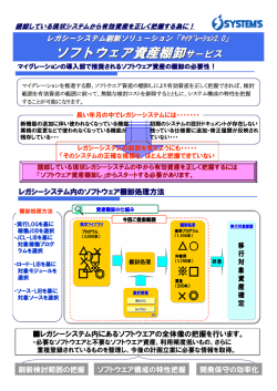
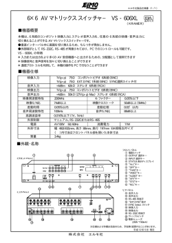
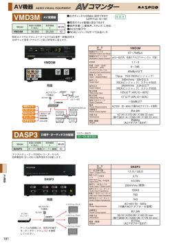
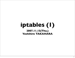
HD CAMERA CONTROL UNIT HDCU-900 SD ANALOG INTERFACE UNIT HKCU-901 HD ANALOG INTERFACE UNIT HKCU-902 FRAME RATE CONVERTER UNIT HKCU-903 LINE CONVERTER UNIT HKCU-904 電気製品は、安全のための注意事項を守らないと、火災 や人身事故になることがあります。 このオペレーションマニュアルには、 事故を防ぐための重要な注意事項と製 品の取り扱いかたを示してあります。 このオペレーションマニュアルをよく お読みのうえ、製品を安全にお使いください。お読みになったあとは、いつ でも見られるところに必ず保管してください。 OPERATION MANUAL 1st Edition (Revised 2) [Japanese/English] 日本語 安全のために ソニー製品は安全に十分に配慮して設計されています。しかし、電気製品は まちがった使い方をすると、火災や感電などにより死亡や大けがなど人身事 故につながることがあり、危険です。 事故を防ぐために次のことを必ずお守りください。 安全のための注意事項を守る 警告表示の意味 このオペレーションマニュア ルおよび製品では、次のよう な表示をしています。表示の 内容をよく理解してから本文 をお読みください。 2(J)∼5(J)ページの注意事項をよくお読みください。 オプション基板の装着について 危険を避けるために、オプション基板の装着はサービストレーニングを受け た技術者、もしくはソニーのサービス担当者または営業担当者にご依頼くだ さい。 この表示の注意事項を守らな いと、火災や感電などにより 死亡や大けがなど人身事故に つながることがあります。 定期点検を実施する 長期間安全に使用していただくために、定期点検を実施することをおすすめ します。点検の内容や費用については、ソニーのサービス担当者または営業 担当者にご相談ください。 この表示の注意事項を守らな いと、感電やその他の事故に よりけがをしたり周辺の物品 に損害を与えたりすることが あります。 故障したら使用を中止する ソニーのサービス担当者または営業担当者にご連絡ください。 注意を促す記号 万一、異常が起きたら 異常な音、 におい、煙 が出たら 炎が出たら c c 1 電源を切る。 2 電源コードや接続コードを抜く。 3 ソニーのサービス担当者または営業担当者に修 理を依頼する。 行為を禁止する記号 すぐに電源を切り、消火する。 行為を指示する記号 目次 警告 .............................................................................................................. 2(J) 注意 .............................................................................................................. 4(J) 概要 .................................................................................................................... 6(J) システム構成例 .................................................................................................. 8(J) 基本構成機器 ........................................................................................................ 8(J) SD 信号システム .................................................................................................... 9(J) HD/SD 信号併用システム.................................................................................. 10(J) 各部の名称と働き ............................................................................................ 11(J) 前面 ...................................................................................................................... 11(J) 後面 ...................................................................................................................... 12(J) SDアナログインターフェースユニットHKCU-901 (別売り) ................................ 17(J) HDアナログインターフェースユニットHKCU-902 (別売り) ............................... 19(J) フレームレートコンバーターユニットHKCU-903 (別売り) ................................... 20(J) ラインコンバーターユニットHKCU-904 (別売り) ................................................ 21(J) 内部基板 .............................................................................................................. 22(J) 仕様 .................................................................................................................. 23(J) HDCU-900 ........................................................................................................... 23(J) HKCU-901 (別売り) ............................................................................................ 25(J) HKCU-902 (別売り) ............................................................................................ 25(J) HKCU-903 (別売り) ............................................................................................ 25(J) HKCU-904 (別売り) ............................................................................................ 26(J) HDC-900シリーズカメラシステムのマニュアル構成 HDC-900シリーズのカメラシステムでは、オペレーションマニュア メンテナンスマニュアルとシステムマニュアルには、 システムの構 ルの他に、メンテナンスマニュアル Part 1、Part 2とシステムマ 築のしかた、設置、接続、システムとして使用するために必要な ニュアルが用意されています。 準備、システムとしての操作など、システム全体に関する説明が オペレーションマニュアルでは、機器の概要、各部の名称と働き、 記載されています。 および仕様など、 その機器固有の機能や特性について説明しま オペレーションマニュアルとメンテナンスマニュアルPart 1は、シ す。 ステムを構成する各機器に付属し、メンテナンスマニュアルPart 2とシステムマニュアルは別売りになっています。 1(J) 日 本 語 下記の注意を守らないと、 火災や感電により死亡や大けがにつながることがあります。 外装を外さない、改造しない 外装を外したり、改造したりすると、感電の原因となります。 内部の調整や設定および点検を行う必要がある場合は、必ずサービストレーニン グを受けた技術者にご依頼ください。 内部に水や異物を入れない 水や異物が入ると火災や感電の原因となります。 万一、水や異物が入ったときは、すぐに電源を切り、電源コードや接続コードを抜い て、 ソニーのサービス担当者または営業担当者にご相談ください。 付属の電源コードを使用する 付属以外の電源コードを使用すると、火災や感電の原因となります。 他の電源コードを使用する場合は、 ソニーのサービス担当者または営業担当者に ご相談ください。 電源コードを傷つけない 電源コードを傷つけると、火災や感電の原因となります。 ・ 電源コードを加工したり、傷つけたりしない。 ・ 重いものをのせたり、引っ張ったりしない。 ・ 熱器具に近づけたり、加熱したりしない。 ・ 電源コードを抜くときは、必ずプラグを持って抜く。 ・ ラックマウントするとき、レールにはさみ込まない。 万一、電源コードが傷んだら、 ソニーのサービス担当者に交換をご依頼ください。 油煙、湯気、湿気、ほこりの多い場所では設置• 使用しない 上記のような場所で設置・使用すると、火災や感電の原因となります。 表示された電源電圧で使用する 機器に表示されたものと異なる電源電圧で使用すると、火災や感電の原因となり ます。 ラックの上部に設置しない 本機は重量があります。 ラックの上部に設置すると、 ラックが転倒してけがの原因 となることがあります。 ラックの下からの高さがおよそ1m以内の位置に設置してくだ さい。 2(J) 機器を固定する 地震などにより機器が転倒・落下すると、大けがの原因となります。 システムマニュ アルに従って機器をラックに固定してください。 ケーブルを傷つけたまま使用しない ケーブルを傷つけたまま使用すると、火災や感電の原因となります。 光ファイバーケーブルは定期的に交換する 光ファイバーケーブルは、劣化したまま使用すると火災や感電の原因となります。 定期的にケーブルを交換してください。 正しいインターフェースで接続する RCP/CNU端子、WF REMOTE端子、MIC REMOTE端子、I/O PORT端子、お よびWF MODE端子に外部機器を接続する場合、接続時のインターフェースが 正しくないと火災や感電の原因となります。 これらの端子への機器の接続はサー ビストレーニングを受けた技術者にご依頼ください。 3(J) 下記の注意を守らないと、 けがをしたり周辺の物品に損害を与えることがあります。 2 台以上積み上げない ラックを使用せずに2台以上積み上げると、製品が落下してけがの原因となること があります。 安定した姿勢でラックマウントする 本機をラックマウントするとき、および取り外すとき、バランスを崩すと機器が落下し てけがの原因となることがあります。安定した姿勢で注意深く作業してください。 2 人以上でラックマウント・運搬する 本機は重量があり、かつ左右のバランスが悪いので、 けがや事故を防ぐため、 ラッ クマウントや運搬は必ず2人以上で行ってください。 ラックは転倒・移動防止の処理をする 地震などによりラックが転倒・移動すると大けがの原因となります。 また、 ラックの設 置状況、強度を充分にお確かめください。 安全アースを接続する 安全アースを接続しないと、感電の原因となることがあります。次の方法でアースを 接続してください。 ・電源コンセントが 3 極の場合 付属の電源コードを使用することで安全アースが接続されます。 ・電源コンセントが 2 極の場合 付属の 3 極→ 2 極変換プラグを使用 し、変換プラグから出ている緑色の アース線を建物に備えられている アース端子に接続してください。 変換プラグ アース線 安全アースを取り付けることができない場合は、 ソニーのサービス担当者にご連絡 ください。 指定の接続ケーブルを使用する 光ファイバーケーブルは、指定のケーブルメーカーに加工をご依頼ください。指定ど おりのものを使用しないと、火災や感電の原因となります。 4(J) 指定以外の機器を接続しない 本マニュアルに記載している以外の機器を接続すると、火災や感電の原因となり ます。(詳しくは12(J)∼20(J)ページを参照) ラックマウントレールに手や指をはさまない ラックマウントした機器を収納するときおよび引き出すとき、 ラックマウントレールに 手や指をはさみ、 けがの原因となることがあります。 指定されたラックマウントレールを使用する 指定以外のラックマウントレールを使用すると、 レールの強度不足により、機器が落 下してけがの原因となることがあります。 通風孔をふさがない 通風孔をふさぐと内部に熱がこもり、火災の原因となることがあります。 ・ 逆さまや横倒しにしない。 ・ 風通しの悪い、狭いところに押し込まない。 ・ 毛足の長いじゅうたんや布団の上に置かない。 ・ 布をかけない。 5(J) 概要 カメラコントロールユニットHDCU-900は、 ソニーのハイデフィニショ 外部同期信号 ンカメラと接続し、信号処理と外部機器とのインターフェースを行う 本機を外部からの同期信号にロックさせることができます。外部同 装置です。 本機は、HD 信号 をSD 信号 に変換するダウンコンバーターと、 期信号としては、HD3 値シンク、または SD 信号のシンク(ブラック SD信号をHD信号に変換するリターンビデオアップコンバーターを バースト)を使用します。 1) 2) 標準装備し、ハイデフィニションカメラシステムはもとより現行カメラ システムとしても運用可能です。 ダウンコンバーター内蔵 本機は、別売りのマスターセットアップユニットMSU-700A/750また システムをフィールド周波数 59.94/50Hzに設定しているときに、 はRCP-700シリーズのリモートコントロールパネルを組み合わせて、 HD信号をダウンコンバーターでSDコンポーネントSDI信号に変換 カメラコントロールシステムを構成します。また、カメラコマンドネッ し出力できます。出力信号のアスペクト比は 4:3 エッジクロップ、 トワークユニットCNU-500/700を使って、複数のビデオカメラをコ 16:9スクイーズ、 レターボックスの設定が可能です。またダウンコン ントロールするシステムを構成することもできます。 バーターには、イメージエンハンサー、ガンマコントロール、マトリッ クスON/OFF 機能があり、外部からのコントロールが可能です。 本機の主な特長は次のとおりです。 アップコンバーター内蔵 多系統ビデオ入出力 SD信号のリターンビデオをHDビューファインダーでモニターする HD-SDI(シリアルデジタルインターフェース)信号の入出力を各4系 ためにアップコンバーターを装備しています。 リターンビデオのアス 統と、SDコンポーネントSDI信号の入出力を各4系統装備していま ペクト比は4:3エッジクロップ、16:9スクイーズ、レターボックスの設 す。各種の別売り基板を装着することにより、次のような信号の入 定が可能です。 出力が可能になります。 SDアナログインターフェースユニットHKCU-901 NTSC、PAL、SDアナログコンポーネント信号の入出力が可能にな ります。 光デジタル伝送 光ファイバーケーブル(シングルモード光ファイバー線2本、電源線 2 本、制御線 2 本)でカメラと本機を接続し、デジタル化したビデ HDアナログインターフェースユニットHKCU-902 オ、音声、制御信号を伝送します。長さ250m の光ファイバーケー HDアナログ信号の入出力が可能になります。 ブルの多段接続により、3000mの信号伝送が可能になります。カメ ラへの給電のケーブル長は、カメラシステムの構成、光ファイバー フレームレートコンバーターユニットHKCU-903 ケーブルの種類で異なります。 24P Cinema Productionシステム時に、従来のHDおよびSD信号 の入出力が可能になります。 ラインコンバーターユニットHKCU-904 720/60P の入出力が可能になります。 安全性を考慮した電源部 電源投入時には、 まず低電圧の電源を送って所定のカメラが接続 されていることを確認した後、正規の AC240Vを供給する安全設 計になっています。光電気複合ケーブルを介してカメラが接続され ていないときは電源を供給しません。 また、ケーブルのオープン、ショートを知らせるアラームインジケー ターを装備しています。 .............................................................................................................................................................................................................................................................. 1) HD 信号(HIGH DEFINITION):1125ラインのHDTV 信号の総称 6(J) 2) SD信号(STANDARD DEFINITION):NTSC/PAL信号、525/625コン ポーネント信号、525/625コンポジット信号の総称 豊富なオーディオ機能 2チャンネルのマイク出力、デジタルオーディオ出力、およびプログ ラムオーディオ用入力端子を装備しています。さらに、独立した 2 チャンネルのインターカムシステムが使用可能で、4線またはRTSイ ンターカムシステムに対応できるようになっています。 ◆ RTSシステムへの対応については、ソニーのサービス担当者または営 業担当者にお問い合わせください。 各種信号のリモートコントロール 本機が出力する各種信号のレベルや位相を、マスターセットアップ ユニットMSU-700A/750 からコントロールすることができます。 マイク音量レベルのコントロール MIC REMOTE端子から、 カメラのマイク音量レベルをコントロール することができます。 キャラクター信号出力 本機の自己診断の状態を文字表示としてSDキャラクター信号を出 力することができます。 ラックマウント可能 本機は19インチのEIA規格標準ラックに組み込むことができます。 高さは 3 ユニットです。 プラグイン方式のユニット構成 内蔵のプリント基板は簡単に抜き差しできる構成です。電源部もプ ラグイン方式のユニット構成になっているので、保守・点検が容易 です。 7(J) システム構成例 基本構成機器 マスターセットアップユニットMSU-700A/750 SDビデオセレクターVCS-700 マルチビットレートルーティングスイッチャーHDS-X3400 • シリアルインプットボードHKDS-X3014 • シリアルアウトプットボードHKDS-X3064 RCP-700シリーズリモート O コントロールパネル I デジタルビデオルーティングスイッチャー DVS-V1201 カメラコマンドネットワーク ユニットCNU-500/700 カメラコントロール ユニット1 カメラ1 光ファイバーケーブル HDカラービデオ カメラHDC-900 HDカメラコントロール ユニットHDCU-900 カメラコントロール ユニット2 カメラ2 光ファイバーケーブル HDカラー HDカメラコントロール ユニットHDCU-900 ビデオカメラ HDC-950 プログラム音声 8(J) インターカムシステム SD信号システム PIX/WF (HKCU-901) HDC-900 VCS-700 HDCU-900(+HKCU-901) CNU-700 HDC-900 HDCU-900(+HKCU-901) MSU-700A/750 PIX/WF (HDCU-900) HDC-950 HDCU-900(+HKCU-901) HDC-950 HDCU-900(+HKCU-901) RCPシリーズ 9(J) システム構成例 HD/SD信号併用システム PIX/WF (HKCU-901) HDC-900 VCS-700 HDCU-900(+HKCU-901) MSU-700A/750 CNU-700 HDC-900 HDCU-900(+HKCU-901) PIX/WF (HDCU-900) HDC-950 HDCU-900(+HKCU-901) HDC-950 HDCU-900(+HKCU-901) RCPシリーズ HD-SDI (Monitor) RCPシリーズ 10(J) MSU-700A/750 各部の名称と働き 前面 1 レッドタリーランプ 2 グリーンタリーランプ 3 MICスイッチ 4 INTERCOMつまみ 8 INTERCOM端子 7 CAMERA POWERスイッチとインジケーター 6 MAIN POWERスイッチとインジケーター 5 CABLE ALARMインジケーター 1 レッドタリーランプ レッドタリー信号を受信したときに点灯します。また、ビデオカメラ、 5 CABLE ALARM(ケーブルアラーム)インジケーター :光ファイバーケーブルの電源供給線が外部シー SHORT(赤) マスターセットアップユニットMSU-700A/750、RCP-700シリーズの スにショートしているか、または2本の電源供給線がショートし リモートコントロールパネルなどでCALLボタンが押されると、 ランプ ているときに点灯し、電源が供給されません。 が点灯していたときは消灯し、消灯していたときは点灯します。付 :後面の CAMERA 端子に光ファイバーケーブルを OPEN(赤) 介してカメラが接続されていないとき点灯します。光ファイ 属のナンバープレートをここに取り付けることができます。 バーケーブルの光受信状態が悪い場合は点滅して警告表示 2 グリーンタリーランプ します。 グリーンタリー信号を受信したときに点灯します。付属のナンバープ レートをここに取り付けることができます。 6 MAIN POWER(主電源)スイッチとインジケーター 本機、ビデオカメラ、およびREMOTE端子に接続したRCP-700シ 3 MIC(マイク選択)スイッチ リーズのリモートコントロールパネルなど、本システム全体の電源を ヘッドセットのマイクの種類を指定したり、マイク入力をOFFすると 「 」側を押すと電源 入 / 切します。 「 」側を押すと電源が入り、 きに使います。 が切れます。電源が入るとインジケーターが点灯します。 DYNAMIC:ダイナミックマイクのとき OFF: マイク入力を切るとき CARBON:カーボンマイクのとき ◆ インターカムラインは、内部のAT基板のスイッチで切り換えます。スイッ チの切り換えについては、22(J)ページを参照してください。また詳しく は、ソニーのサービス担当者または営業担当者にお問い合わせくださ い。 4 INTERCOM(インターカム音量調節)つまみ インターカムの受信レベルを調整します。 ◆ プログラムオーディオのミックス音量は内部の AT 基板で設定します。 ミックス音量の設定については、22(J)ページを参照してください。また 詳しくは、ソニーのサービス担当者または営業担当者にお問い合わせ ください。 7 CAMERA POWER(カメラ電源)スイッチとインジケー ター MAIN POWERスイッチが入側になっているとき、 このスイッチでビ デオカメラの電源を入 / 切します。 「 」側を押すと電源が入り、 「 」側を押すと電源が切れます。 リモートコントロールパネルが接続されている場合に、 リモートコント ロールパネルのCAM PWボタンで給電がOFFされていると、本ス イッチだけではビデオカメラの電源を入れることはできません。 8 INTERCOM(インターカム)端子(XLR 5ピン) ヘッドセットを接続します。 ◆ XLR 5ピン以外のプラグの付いたヘッドセットをお使いになるときは、ソ ニーのサービス担当者または営業担当者にお問い合わせください。 11(J) 各部の名称と働き 後面 1 CAMERA端子 HD信号入出力端子部(13(J)ページ) SD信号入出力端子部(14(J)ページ) 8 拡張スロット 2 ∼AC IN端子 3 リモート端子部 4 CHARACTER OUTPUT端子 5 DIGITAL AUDIO端子 6 MIC OUTPUT端子 7 INTERCOM/TALLY/PGM端子 1 CAMERA(カメラ)端子(光ファイバーコネクター) 3 リモート端子部 ビデオカメラと光ファイバーケーブル FC2-PD50/PD250などで接 続します。電源、コントロール信号、ビデオ信号、音声信号など、ビ 1 RCP/CNU REMOTE端子 デオカメラのすべての信号を光ファイバーケーブル1本で送受信す 2 WF REMOTE端子 ることができます。 3 TRUNK LINE端子 ご注意 REMOTE WF 光ファイバーケーブルの接続端面にほこりなどが付着すると、伝送 TRUNK LINE RCP/CNU エラーが発生しますので、接続しないときは、必ず付属のキャップ MIC I/O PORT をはめてください。 4 MIC REMOTE端子 2 ∼AC IN(AC電源入力)端子 5 I/O PORT端子 付属の電源コードでAC電源に接続します。付属のプラグホルダー で電源コードを本機に固定することができます。 1 RCP/CNU REMOTE(RCP/CNUリモート)端子(8ピ ン) 接続ケーブルCCA-5を使って、マスターセットアップユニットMSU700A/750またはカメラコマンドネットワークユニットCNU-500/700、 RCP-700シリーズのリモートコントロールパネルのを接続します。こ の端子を介して、 コントロール信号を送受信します。RCP-700シリー ズを接続したときは、電源も供給します。 12(J) 2 WF REMOTE(波形モニターリモート)端子(D-Sub 15 ピン) 4 CHARACTER OUTPUT(キャラクター出力)端子 (BNC型) 波形モニターの表示をマスターセットアップユニットMSU-700A/750 本機の自己診断結果をSD白黒アナログビデオ信号として出力し またはRCP-700シリーズのリモートコントロールパネルでリモートコン ます。 トロールするとき、波形モニターの対応する端子と接続します。リ コール式波形モニターと1730HD/1735HD波形モニターを接続す 5 DIGITAL AUDIO(デジタルオーディオ出力)端子(BNC ることができます。 リコール式波形モニターでは、表示モードを波形 型) モニターで設定(プリセット)し、そのモードを外部から選択(リコー ビデオカメラに入力されたデジタルオーディオ信号を出力します。 ル)します。AT 基板内のスイッチでリコール方式か、1730HD/ 1735HD 方式のいずれかを選択することができます。 6 MIC OUTPUT(マイク出力)端子(XLR 3ピン) ビデオカメラに入力されたマイク信号を出力します。 ◆ AT基板内のスイッチの設定については、ソニーのサービス担当者また は営業担当者にお問い合わせください。 3 TRUNK LINE(トランクライン)端子(D-Sub 9ピン、 RS-232C準拠) HDカラービデオカメラHDC-900 のTRACKER 端子とRS-232C で 7 INTERCOM/TALLY/PGM(インターカム/タリー/プロ グラムオーディオ)端子(D-Sub 25ピン) インターカム、タリー、プログラムオーディオの各信号を入出力しま す。インターカムシステムのインターカム/タリー/プログラムオー ディオ端子と接続します。 インターフェースするための端子です。主にカメラ側で用いる機器 との通信回線用として使用します。この端子を使用し、RXD、 TXD、RTS、CTS信号を最大通信速度19.2kbpsで伝送することが できます。 ◆ CCUシステム拡張用のRS-232C端子として使用することもできます。設 定については、 ソニーのサービス担当者または営業担当者にお問い合 わせください。 4 MIC REMOTE(マイクリモート)端子(D-Sub 15ピン) 8 拡張スロット 別売りのSDアナログインターフェースユニットHKCU-901、HDアナ ログインターフェースユニットHKCU-902、フレームレートコンバー ターユニットHKCU-903、またはラインコンバーターユニットHKCU904を取り付けます。 ◆ 取り付けについては、ソニーのサービス担当者または営業担当者にお 問い合わせください。 オーディオミキサーなどの外部コントロール機器から、このコネク ターを介して、ビデオカメラのマイク入力レベルを5 段階(− 60/ −50/−40/−30/−20 dB)に設定することができます。撮影時の 音量条件によって適正なレベルに設定してください。 レッドタリー、グリーンタリー信号を出力します。 ◆ マイク入力レベルは、本機内部の基板内のスイッチで設定することもで きます。設定については、22(J)ページを参照してください。また詳しく は、ソニーのサービス担当者または営業担当者にお問い合わせくださ い。 5 I/O PORT(I/Oポート)端子(D-Sub 15ピン) 外部コントロ−ル機器とのリモ−トコントロ−ル用です。 ご注意 幅 42 mm 以上の D-Subケースを使用すると、245 の端子が干 渉します。JAE 製 DA-C1-J10 の使用をお勧めします。 13(J) 各部の名称と働き HD信号入出力端子部 1 SERIAL RET INPUT 1∼4端子 2 REFERENCE IN端子 3 PROMPTER IN端子 4 SERIAL OUTPUT 1∼3端子 5 SERIAL OUTPUT MONI端子 1 2 3 SERIAL RET INPUT 4 1 REFERENCE IN PROMPTER IN 1 SERIAL RET INPUT 1∼4(HD-SDIリターンビデオ 1、2、3、4入力)端子( BNC型) 4系統のHD-SDIリターンビデオ信号を個別に入力することができ 2 3 MONI SERIAL OUTPUT 4 SERIAL OUTPUT1∼3(HD-SDI 1、2、3出力)端子 (BNC型) ビデオカメラからの信号をHD-SDI 信号で 3 系統出力します。 ます。RET 1∼RET 4の選択は、カメラ側のリターンスイッチで行い ます。 5 SERIAL OUTPUT MONI(モニター用HD-SDI出力) 端 RET 1、2、3、4 の各系統に接続する信号は、本機の AT 基板内ス 子(BNC型) イッチまたはマスターセットアップユニットMSU-700A/750で選択す ビデオカメラからの信号にスキントーンゲート信号と各種アスペクト ることができます。 マーカーをミックスして HD-SDI 信号で出力します。 ◆ AT基板内のスイッチの操作については、ソニーのサービス担当者また は営業担当者にお問い合わせください。 ◆ マスターセットアップユニットのマニュアルも併せてご覧ください。 ◆ 本機のAT基板内のスイッチまたはMSU-700A/750からミックスのON/ OFFの設定が可能です。設定方法については、 ソニーのサービス担当 者または営業担当者にお問い合わせください。 2 REFERENCE IN(リファレンス入力)端子(BNC型) 外部同期用のHD3 値基準同期信号または SD 基準同期信号(ブ ラックバースト信号)を入力します。使用しないループスルー端子は 75 Ωで終端してください。 ご注意 HKCU-901のVBS信号を使用する場合(SC位相ロックが必要な場 合)は、SD 基準同期信号(ブラックバースト信号)を使用してくださ い。 3 PROMPTER IN(プロンプター入力)端子(BNC型) プロンプター用信号を入力します。使用しないループスルー端子は 75Ωで終端してください。信号は、1.0Vp-p、75Ωのアナログ信号 であれば、信号規格を問わず周波数帯域8MHzでビデオカメラの PROMPTER OUT 端子から出力することができます。 14(J) SD信号入出力端子部 このSD信号入出力端子部は、別売りのHKCU-902/903/904に交 換することもできます。 2 SYNC OUT端子 3 PIX OUT端子 4 WF OUT端子 1 SERIAL RET INPUT 1∼4端子 5 WF MODE端子 6 SERIAL OUTPUT 1∼4端子 1 2 3 SERIAL RET INPUT 4 1 SYNC OUT PIX OUT WF OUT WF MODE 2 3 4 SERIAL OUTPUT 1 SERIAL RET INPUT 1∼4(SD-SDIリターンビデオ 3 PIX OUT(ピクチャーモニター出力)端子(BNC型) 1、2、3、4入力)端子( BNC型) RCP-700シリー ズリモートコントロー ル パ ネ ル の MONITOR フィールド周波数59.94/50 Hzでシステムが動作しているときに、4 SELECTボタン、またはマスターセットアップユニットMSU-700A/ 系統のSD-SDIリターンビデオ信号を個別に入力することができま 750 の PICTURE MONITORボタンで選択した、ピクチャーモニ す。 ター用ビデオ信号が出力されます (RCPとMSUを同時使用してい RET 1∼ RET 4 の選択はカメラ側のリターンスイッチで行います。 る場合は、RCPコントロール用の出力端子となります) 。 RET 1、2、3、4 の各系統に接続する信号は、本機のAT 基板内ス イッチまたはマスターセットアップユニットMSU-700A/750で選択す ることができます。また、SD信号では、アスペクト比も選択可能で す。 ◆ AT基板内のスイッチの操作については、ソニーのサービス担当者また は営業担当者にお問い合わせください。 ◆ マスターセットアップユニットのマニュアルも併せてご覧ください。 ◆ 操作については、マスターセットアップユニットおよびリモートコントロール パネルのマニュアルをご覧ください。 4 WF OUT(波形モニター出力)端子(BNC型) RCP-700シリーズ のリモートコントロール パネル の MONITOR SELECTボタンまたはマスターセットアップユニットMSU-700A/750 のWF MONITORボタンで選択した波形モニター用ビデオ信号が 出力されます(RCPとMSUを同時使用している場合は、RCPコン ご注意 トロール用の出力端子となります) 。 HDCU-900と非同期の信号を入力した場合、画質が悪くなる場合 があります。 ◆ 操作については、マスターセットアップユニットおよびリモートコントロール パネルのマニュアルをご覧ください。 2 SYNC OUT(HD/SD同期信号出力)端子(BNC型) 内部の同期信号発生器からの HD3 値同期信号または SDコンポ ジットシンクが出力されます。(工場設定: HD3 値同期信号) ご注意 34から出力されるVBS 信号のSC 位相は、REFERENCE IN 端 子からのブラックバースト信号とはロックしていません。モニターは ◆ 信号の選択方法については、 ソニーのサービス担当者または営業担当 者にお問い合わせください。 内部同期モードで使用してください。 15(J) 各部の名称と働き 5 WF MODE(波形モニターモード出力)端子(4ピン) 波形モニターを使って、 シーケンシャルモードで信号をモニターす るとき、波形モニターの対応する端子と接続します。RCP-700シリー ズリモートコントロールパネルまたはMSU-700A/750のSEQボタン を押すと、シーケンス信号が出力され、R、G、B信号をシーケンシャ ルモードで、3 波形同時にモニターすることができます。 (RCPと MSUを同時使用している場合は、RCPコントロール用の出力端子 となります) 。 ◆ 操作については、 リモートコントロールパネルのマニュアルをご覧くださ い。 6 SERIAL OUTPUT 1∼4(SD-SDI 1、2、3、4出力)端 子(BNC型) フィールド周波数59.94/50 Hzでシステムが動作しているときに、 ビ デオカメラからの信号を SDコンポーネントSDI 信号にダウンコン バートして 4 系統出力します。 ◆ 設定方法については、 ソニーのサービス担当者または営業担当者にお 問い合わせください。 16(J) SDアナログインターフェースユニットHKCU-901 (別売り) ご注意 本機の拡張スロットに取り付けます。 フィールド周波数59.94/50 Hzでシステムが動作しているときには、 ◆ 取り付けについては、ソニーのサービス担当者または営業担当者にお 問い合わせください。 各入出力端子が機能しますが、フィールド周波数60Hzのときには 機能しません。 2 SYNC OUT端子 3 PIX OUT端子 1 RET INPUT 1∼4端子 4 WF OUT端子 5 Y/G、B−Y/B、R− Y/R OUTPUT端子 6 VBS OUT 1、2端子 1 2 3 RET INPUT 4 Y/G SYNC OUT PIX OUT WF OUT B-Y/B R-Y/R OUTPUT 1 2 VBS OUT 1 RET INPUT 1∼4(リターンビデオ1、2、3、4入力)端 3 PIX OUT(ピクチャーモニター出力)端子(BNC型) 子(BNC型) RCP-700シリー ズリモートコントロー ル パ ネ ル の MONITOR 4 系統の SDアナログリターンビデオ信号を個別に入力することが SELECTボタン、またはマスターセットアップユニットMSU-700A/ できます。RET 1∼RET 4の選択はカメラ側のリターンスイッチで行 750 の PICTURE MONITORボタンで選択した、ピクチャーモニ います。RET 1、2、3、4の各系統に接続する信号は、本機のAT基 ター用ビデオ信号が出力されます (RCPとMSUを同時使用してい 板内スイッチまたはマスターセットアップユニットMSU-700A/750で る場合は、MSUコントロール用の出力端子とすることも可能です) 。 選択することができます。また、SD信号では、アスペクト比も選択 信号の選択は、AT 基板内スイッチで行います。 可能です。 ◆ AT基板内のスイッチの操作については、ソニーのサービス担当者また は営業担当者にお問い合わせください。 ◆ マスターセットアップユニットのマニュアルも併せてご覧ください。 ご注意 HDCU-900と非同期の信号を入力した場合、画質が悪くなる場合 があります。 2 SYNC OUT(SD同期信号出力)端子(BNC型) 内部の同期信号発生器からのSDコンポジットシンクが出力されま す。 ◆ 操作については、マスターセットアップユニットおよびリモートコントロール パネルのマニュアルをご覧ください。 ◆ AT基板内のスイッチの操作については、ソニーのサービス担当者また は営業担当者にお問い合わせください。 4 WF OUT(波形モニター出力)端子(BNC型) RCP-700シリーズ のリモートコントロール パネル の MONITOR SELECTボタンまたはマスターセットアップユニットMSU-700A/750 のWF MONITORボタンで選択した波形モニター用ビデオ信号が 出力されます(RCPとMSUを同時使用している場合は、MSUコン トロール用の出力端子とすることも可能です) 。信号の選択は、AT 基板内スイッチで行います。 ◆ 操作については、マスターセットアップユニットおよびリモートコントロール パネルのマニュアルをご覧ください。 ◆ AT基板内のスイッチの操作については、ソニーのサービス担当者また は営業担当者にお問い合わせください。 17(J) 各部の名称と働き 5 Y/G、B−Y/B、R−Y/R OUTPUT(コンポーネントビデ オ信号出力)端子(BNC型) Y、B−Y、R−Yコンポーネントビデオ信号または G、B、Rコンポー ネントビデオ信号を1 系統出力します。信号の種類は、AT 基板内 スイッチで選択します。 (工場設定: G、B、R) ◆ AT基板内のスイッチの操作については、ソニーのサービス担当者また は営業担当者にお問い合わせください。 6 VBS OUT 1、2(コンポジットビデオ信号出力1、2)端 子(BNC型) ビデオカメラからの信号をアナログコンポジットビデオ信号で2系統 出力します。 18(J) HDアナログインターフェースユニットHKCU-902(別売り) 本機の拡張スロットに取り付けます。SD信号入出力端子部を取り外 して取り付けることも可能です。 ◆ 取り付けについては、ソニーのサービス担当者または営業担当者にお 問い合わせください。 1 RET INPUT 1∼4端子 2 SYNC OUT端子 3 PIX OUT端子 4 OUTPUT 1、2端子 1 2 3 RET INPUT 4 Y/G SYNC OUT PIX OUT PB/B PR/R Y/G OUTPUT 1 PB/B PR/R OUTPUT 2 1 RET INPUT 1∼4(リターンビデオ1、2、3、4入力)端 4 OUTPUT 1、2( HDアナログコンポーネントビデオ 1、 子(BNC型) 2出力)端子(BNC型) 4系統のHDアナログリターンビデオ信号を個別に入力することが HDアナログコンポーネントビデオ信号をY、PB、PR または G、B、R できます。RET 1∼RET 4の選択はカメラ側のリターンスイッチで行 の形で出力します。Y、PB、PR あるいはG、B、Rのいずれの形で出 います。RET 1、2、3、4の各系統に接続する信号は、本機のAT基 力するかは、本機のAT基板内スイッチでOUTPUT 1、OUTPUT 2 板内スイッチまたはマスターセットアップユニットMSU-700A/750で それぞれに独立で選択することができます。 (工場設定: G、B、R) 選択することができます。 ◆ AT基板内のスイッチの操作については、ソニーのサービス担当者また は営業担当者にお問い合わせください。 ◆ マスターセットアップユニットのマニュアルも併せてご覧ください。 ◆ AT基板内のスイッチの操作については、ソニーのサービス担当者また は営業担当者にお問い合わせください。 2 SYNC OUT(HD同期信号出力)端子(BNC型) 内部の同期信号発生器からの HD3 値同期信号を出力します。 3 PIX OUT(HDピクチャーモニター出力)端子(BNC型) RCP-700シリーズ のリモートコントロール パネル の MONITOR SELECTボタンまたはマスターセットアップユニットMSU-700A/750 の PICTURE MONITORボタンで選択したピクチャーモニター用 ビデオ信号が出力されます。 リモートコントロールパネルまたはマス ターセットアップユニットの選択は後押し優先で動作します。 ◆ 操作については、マスターセットアップユニットおよびリモートコントロール パネルのマニュアルをご覧ください。 19(J) 各部の名称と働き フレームレートコンバーターユニットHKCU-903(別売り) ◆ 取り付けについては、ソニーのサービス担当者または営業担当者にお 問い合わせください。 本機の拡張スロットに取り付けます。SD信号入出力端子部を取り外 して取り付けることも可能です。 1 SERIAL RET INPUT 1∼4端子 2 SYNC OUT端子 3 FRAME REFERENCE IN/OUT端子 4 SERIAL OUTPUT 1∼3、MONI端子 1 2 3 SERIAL RET INPUT 4 IN SYNC OUT SYNC OUT OUT 1 FRAME REFERENCE 2 3 MONI SERIAL OUTPUT 1 SERIAL RET INPUT 1∼4(HD-SDIリターンビデオ 1、2、3、4入力)端子( BNC型) ス入力/出力)端子(BNC型) 4系統のHD-SDIリターンビデオ信号を個別に入力することができ IN端子にはカメラコントロールユニット間のフレームシーケンスロッ ます。RET 1∼RET 4の選択はカメラ側のリターンスイッチで行いま ク用の HD 3 値基準同期信号または SD 基準同期信号(ブラック 3 FRAME REFERENCE IN/OUT(フレームリファレン す。 バースト信号)を入力します。この場合OUT端子からは、IN端子に この基板のRET 1、2、3、4の各系統に接続する信号は、本機のAT 入力された信号がそのまま出力されます。 基板内スイッチまたはマスターセットアップユニットMSU-700A/750 本機をマスター機として使用する場合は、プルダウン用のフレーム で選択することができます。 シンクパルス信号の出力端子として使用することができます。 切り換えは FC 基板内スイッチで行います。 ◆ AT基板内のスイッチの操作については、ソニーのサービス担当者また は営業担当者にお問い合わせください。 ◆ マスターセットアップユニットのマニュアルも併せてご覧ください。 ◆ FC基板内のスイッチの操作については、ソニーのサービス担当者また は営業担当者にお問い合わせください。 2 SYNC OUT(HD/SD同期信号出力)端子(BNC型) 4 SERIAL OUTPUT 1∼ 3、MONI( 1、2、3、モニター 左側の端子からは上部スロットの端子と同じフォーマットの同期信号 出力)端子(BNC型) が出力されます。 1∼3端子からは、ビデオカメラからの信号をHD-SDI信号として3 右側の端子からはSERIAL OUTPUT 1∼3端子と同じフォーマット 系統出力します。 のHD 3 値同期信号が出力されます。 MONI端子からは、ビデオカメラからの信号にスキンゲート信号と 各種アスペクトマーカーをミックスしてHD-SDI信号として出力しま す。 20(J) ラインコンバーターユニットHKCU-904(別売り) 本機の拡張スロットに取り付けます。SD信号入出力端子部を取り外 して取り付けることも可能です。 ◆ 取り付けについては、ソニーのサービス担当者または営業担当者にお 問い合わせください。 1 SERIAL RET INPUT 1∼4端子 2 SYNC OUT端子 3 SERIAL OUTPUT 1∼3端子 1 2 3 SERIAL RET INPUT 4 1 SYNC OUT 2 3 SERIAL OUTPUT SYNC OUT 1 SERIAL RET INPUT 1∼ 4(HD-SDIリターンビデオ 3 SERIAL OUTPUT 1∼3(1、2、3出力)端子(BNC型) 1、2、3、4入力)端子( BNC型) ビデオカメラからの信号をHD-SDI信号(720/60P)として3系統出 4系統のHD-SDIリターンビデオ信号(720/60P)を個別に入力する 力します。 ことができます。RET 1∼RET 4の選択はカメラ側のリターンスイッ チで行います。 この基板のRET 1、2、3、4の各系統に接続する信号は、本機のAT 基板内スイッチまたはマスターセットアップユニットMSU-700A/750 で選択することができます。 ◆ AT基板内のスイッチの操作については、ソニーのサービス担当者また は営業担当者にお問い合わせください。 ◆ マスターセットアップユニットのマニュアルも併せてご覧ください。 2 SYNC OUT(HD/SD同期信号出力)端子(BNC型) 左側の端子からは上部スロットの端子と同じフォーマットの同期信号 が出力されます。 右側の端子からはSERIAL OUTPUT 1∼3端子と同じフォーマット の HD 3 値同期信号が出力されます。 21(J) 各部の名称と働き 内部基板 DPR基板 AUDIO PHASE調整つまみ DPR SYSTEM POWER POWER /1.001 MAIN OUTPUT 60 50 30 25 PsF CHU LOCK 24 AUDIO PHASE OPTICAL CONDITION CCU 540P 1035 CHU AUDIO PHASE(オーディオ位相)調整つまみ 本機から出力される音声信号の映像信号に対するディレイ量を調 整します。 (1ステップ =5 msec、1フレームディレイ:30フレーム/ 秒 =7、25フ レーム/ 秒 =8) AT基板 1 INCOM SELECTスイッチ 2 PGM MIXつまみ 3 SIDE TONEつまみ 4 TALK LEVELつまみ AT REFERENCE H PHASE POWER /1.001 REF GEN IN LOCK REMOTE LOCAL MIC LEVEL NORM NORM HD BB MIN FINE CH-1 CCU INCOM SELECT TALK 2 WIRE LEVEL CANCEL MIN CH-2 ENG PROD PGM SIDE PRIVATE MIX TONE PROD ENG 5 MIC LEVELCH-1/CH-2つまみ 1 INCOM SELECT(インターカム選択)スイッチ 3 SIDE TONE(サイドトーン)つまみ 本機のインカム端子を介して入出力されるインターカム信号の接続 ヘッドセットのレシーバーに入る自分の音声のレベルを調整します。 先を選択します。 PROD: プロデューサーラインに接続されます。 PRIVATE: 本機とプロデューサーラインまたはエンジニアラインと の接続が切れ、本機とカメラ間の通話のみ可能になります。 4 TALK LEVEL(トークレベル)つまみ プロデューサーライン、エンジニアライン、およびカメラのヘッドセッ トに送られる自分の音声のレベルを調整します。 ENG: エンジニアラインに接続されます。 5 MIC LEVEL CH-1/CH-2(チャンネル1/2マイクレベル) 2 PGM MIX(プログラムミックス)つまみ つまみ ヘッドセットのインカムにミックスされるプログラム音声のレベルを調 カメラの MIC 端子に接続されるマイクの感度に応じて、適正な音 整します。 量が得られるようにレベルを調整します。 22(J) 仕様 入出力端子 HDCU-900 CAMERA 光ファイバーコネクター(1) 1.485/1.4835Gbps SDI×2、AC240V 給電 一般 INCOM/TALLY/PGM 電源 AC 100/110-120/220-240 V、50/60 Hz D-Sub 25ピンコネクター(1) (各電圧への切り換えは、ソニーの • INCOM-4W-2 系統(PD/ENG)、0 dB サービス担当者または営業担当者に • PGM-2 系統、0/− 20dB お問い合わせください。) 消費電流 5.4 A (全システム動作時、AC 100V) 動作温度 5℃∼ 40℃ 保存温度 −20℃∼+ 60℃ 質量 約 20 kg • TALLY(R、G) RCP/CNU REMOTE 8ピンマルチコネクター(1) TRUNK LINE D-Sub 9ピン、メス(1)、RS-232C、 CHU 伝送またはシステム拡張用 外形寸法図 (単位:mm ) I/O PORT D-Sub 15ピン、メス(1) (推奨 JAE 製 DA-C1-J10) 入力端子 AC IN 1 系統、100/110-120/220-240V (スイッチで 460 切り換え) HD SERIAL RET INPUT BNC 型(4)、SMPTE 292M ビットレート1.485 Gbps/1.4835 Gbps SD SERIAL RET INPUT BNC 型(4)、SMPTE 259M ビットレート270 Mbps BNC 型(2)、ループスルー出力 133 57.2 REFERENCE INPUT HD:SMPTE 274M、3 値シンク、0.6 Vp-p、 75 Ω 424 465 481 SD:ブラックバースト(または NTSC 10F-BB)、0.286 Vp-p、75 Ω PROMPTER IN BNC 型(2)、ループスルー出力、 アナログ信号、1.0 Vp-p、75 Ω 設置環境 MIC REMOTE D-Sub 15ピン(1) (推奨 JAE 製 DA-C1-J10) • 高温の部屋や熱源の近くは避けること。 • 強電界や強磁界の場所に置かないこと。 出力端子 • 乾燥した通風の良い場所であること。 • 太陽光線、強力ライトなどが直接あたる場所は避けること MIC OUT XLR 3ピン、オス(2)、0dBs/− 20dBs DIGITAL AUDIO OUT BNC 型(1)、AES/EBUフォーマット CHARACTER OUT BNC 型(1)、525/625 白黒 WF REMOTE D-Sub 15ピン、メス(1) (推奨 JAE 製 DA-C1-J10) 23(J) 仕様 HD SERIAL OUTPUT 別売り品 BNC 型(3)、SMPTE 292M、0.8 Vp-p、 75 Ω ビットレート 1.485 Gbps/1.4835 Gbps HD SERIAL MONITOR OUTPUT ラインコンバーターユニットHKCU-904 75 Ω 光ファイバーケーブル FC2-PD50 (50m) ビットレート 1.485 Gbps/1.4835 Gbps 光ファイバーケーブル FC2-PD250 (250m) 接続ケーブル CCA-5-3 (3m)、CCA-5-10 (10m) BNC 型(4)、SMPTE 259M、0.8 Vp-p、 延長基板 BKP-7900 75 Ω システムマニュアル ビットレート 270Mbps メンテナンスマニュアル Part 2 BNC 型(1) HD:BTA-S001A、3 値シンク、0.6 Vp-p、 75 Ω PIX OUT HDカラービデオカメラ HDC-900/950 HD SYNC/SD SYNC 切り換え可能 HDスタジオビルドアップユニットHKCA-700 BNC 型(1)、VBS/R/G/B HD エレクトロニックビューファインダーHDVF-700A BNC 型(1)、VBS/R/G/B (VBS 1Vp-p、75 Ω) WF MODE 関連機器 SD:コンポジットシンク、0.3 Vp-p、75 Ω (VBS 1Vp-p、75 Ω) WF OUT HDアナログインターフェースユニットHKCU-902 フレームレートコンバーターユニットHKCU-903 BNC 型(1)、SMPTE 292M、0.8 Vp-p、 SD SERIAL OUTPUT SYNC OUT SDアナログインターフェースユニットHKCU-901 4ピン(1) HD エレクトロニックビューファインダーHDVF-20A リモートコントロールパネル RCP-700シリーズ HDマスターセットアップキットHKCF-700 マスターセットアップユニットMSU-700A/750 ビデオセレクター VCS-700 カメラコマンドネットワークユニット CNU-700/500 付属品 マルチビットレートルーティングスイッチャーHDS-X3400 AC 電源コード(1) 電源コード用プラグホルダー(1) 本機は「高調波ガイドライン適合品」です。 3ピン/2ピン変換 ACプラグ(1) 4ピンコネクター(1) 仕様および外観は、改良のため予告なく変更することがありますが ナンバープレート(1 式) ご了承ください。 ヒューズ(1 式) オペレーションマニュアル(1) メンテナンスマニュアル Part 1 (1) 24(J) HKCU-901(別売り) 一般 HKCU-902(別売り) 一般 動作温度 5℃∼ 40℃ 動作温度 5℃∼ 40℃ 保存温度 −20℃∼+ 60℃ 保存温度 − 20℃∼+ 60℃ 外形寸法 (幅×高さ×奥行き) 外形寸法 (幅×高さ×奥行き) IF 基板:約 330×230×21 mm VDA 基板:約 255×128×30 mm 質量 ADA 基板:約 255×128×30 mm 質量 約 0.6 kg 約 1.3 kg 入力端子 入力端子 RET INPUT RET INPUT BNC 型(4)、1.0Vp-p、75 Ω、VBS 出力端子 VBS OUT BNC 型(4)、HD SMPTE 274M (Y) 1.0 Vp-p、75 Ω 出力端子 BNC 型(2)、1.0Vp-p、75 Ω、VBS Y/G、PB/B、PR/R OUT Y/G、B− Y/B、R− Y/R OUTPUT BNC 型(2 系統、各 1)、SMPTE 274M BNC 型(2) Y/R/G/B: 1.0 Vp-p、75Ω R/G/B:0.7Vp-p、(100%ホワイト)、75 Ω PB/PR: 0.7 Vp-p、75Ω Y、PB、PR/G、B、R 切り換え可能 コンポーネントビデオ Y: 0.714 Vp-p (100%ホワイト) SYNC OUT BNC 型(1)、BTA-S001A、3 値シンク、 0.6 Vp-p、75 Ω R−Y/B− Y:0.756 Vp-p、75 Ω (75%カラーバー) SD SYNC OUT BNC 型(1)、コンポジットシンク、0.3 Vp-p、 PIX OUT BNC 型(1)、VBS/R/G/B (VBS: 1.0Vp-p、 PIX OUT BNC 型(1)、SMPTE 274M、Y/R/G/B、 1.0Vp-p、75 Ω 75 Ω 75 Ω) WF OUT 仕様および外観は、改良のため予告なく変更することがあります が、ご了承ください。 BNC 型(1)、VBS/R/G/B (VBS: 1.0Vp-p、 75 Ω) 仕様および外観は、改良のため予告なく変更することがあります HKCU-903(別売り) が、ご了承ください。 一般 動作温度 5℃∼ 40℃ 保存温度 − 20℃∼+ 60℃ 外形寸法 (幅×高さ×奥行き) FC 基板:約 330×230×21 mm SDI 基板:約 255×128×30 mm 質量 約 1.3 kg 25(J) 仕様 入出力端子 HKCU-904 (別売り) FRAME REFERENCE BNC 型(2) 一般 HD:SMPTE 274M、3 値シンク入力、 0.6 Vp-p、75 Ω SD:ブラックバースト入力、0.286 Vp-p、 75 Ω 動作温度 5℃∼ 40℃ 保存温度 −20℃∼+ 60℃ 外形寸法 (幅×高さ×奥行き) LC 基板:約 330×230×21 mm ループスルー出力またはフレームシンクパ SDI 基板:約 255×128×30 mm ルス出力、0.3 Vp-p、75 Ω切り換え可能 質量 入力端子 約 1.3 kg 入力端子 HD SERIAL RET INPUT BNC 型(4)、SMPTE 292M HD SERIAL RET INPUT BNC 型(4)、SMPTE 292M (720/60P) ビットレート1.485 Gbps/1.4835 Gbps ビットレート1.485 Gbps/1.4835 Gbps 出力端子 出力端子 HD SERIAL OUTPUT BNC 型(3)、SMPTE 292M、0.8 Vp-p、 HD SERIAL OUTPUT BNC 型(3)、SMPTE 292M (720/60P)、 75 Ω 0.8 Vp-p、75 Ω ビットレート1.485 Gbps/1.4835 Gbps ビットレート1.485 Gbps/1.4835 Gbps HD SERIAL MONITOR OUTPUT BNC 型(1)、SMPTE 292M、0.8 Vp-p、 SYNC OUT(左) SD:コンポジットシンク、0.3 Vp-p、75 Ω 75 Ω (上部スロットにRC 基板が装着されて ビットレート1.485 Gbps/1.4835 Gbps SYNC OUT(左) いるとき) BNC 型(1) HD:BTA-S1101、3 値シンク、0.6 Vp-p、 SD:コンポジットシンク、0.3 Vp-p、75 Ω 75 Ω (上部スロットに RC 基板が装着されて いるとき) BNC 型(1) SYNC OUT(右) BNC 型(1) HD: 720/60P、3値シンク、0.6 Vp-p、75Ω HD:BTA-S1101、3 値シンク、0.6 Vp-p、 75 Ω SYNC OUT(右) BNC 型(1) HD:BTA-S1101、3 値シンク、0.6 Vp-p、 75 Ω 仕様および外観は、改良のため予告なく変更することがあります が、ご了承ください。 26(J) 仕様および外観は、改良のため予告なく変更することがあります が、ご了承ください。 English To prevent fire or shock hazard, do not expose the unit to rain or moisture. To avoid electrical shock, do not open the cabinet. Refer servicing to qualified personnel only. VORSICHT Um Feuergefahr und die Gefahr eines elektrischen Schlages zu vermeiden, darf das Gerät weder Regen noch Feuchtigkeit ausgesetzt werden. Um einen elektrischen Schlag zu vermeiden, darf das Gehäuse nicht geöffnet werden. Überlassen Sie Wartungsarbeiten stets nur qualifiziertem Fachpersonal. For customers in the USA This equipment has been tested and found to comply with the limits for a Class A digital device, pursuant to Part 15 of the FCC Rules. These limits are designed to provide reasonable protection against harmful interference when the equipment is operated in a commercial environment. This equipment generates, uses, and can radiate radio frequency energy and, if not installed and used in accordance with the instruction manual, may cause harmful interference to radio communications. Operation of this equipment in a residential area is likely to cause harmful interference in which case the user will be required to correct the interference at his own expense. You are cautioned that any changes or modifications not expressly approved in this manual could void your authority to operate this equipment. The shielded interface cable recommended in this manual must be used with this equipment in order to comply with the limits for a digital device pursuant to Subpart B of Part 15 of FCC Rules. For the customers in Europe This product with the CE marking complies with both the EMC Directive (89/336/EEC) and the Low Voltage Directive (73/23/EEC) issued by the Commission of the European Community. Compliance with these directives implies conformity to the following European standards: • EN60950: Product Safety • EN55103-1: Electromagnetic Interference (Emission) • EN55103-2: Electromagnetic Susceptibility (Immunity) This product is intended for use in the following Electromagnetic Environment(s): E1 (residential), E2 (commercial and light industrial), E3 (urban outdoors) and E4 (controlled EMC environment, ex. TV studio). Pour les clients européens Ce produit portant la marque CE est conforme à la fois à la Directive sur la compatibilité électromagnétique (EMC) (89/ 336/CEE) et à la Directive sur les basses tensions (73/23/ CEE) émises par la Commission de la Communauté Européenne. La conformité à ces directives implique la conformité aux normes européennes suivantes: • EN60950: Sécurité des produits • EN55103-1: Interférences électromagnétiques (émission) • EN55103-2: Sensibilité électromagnétique (immunité) Ce produit est prévu pour être utilisé dans les environnements électromagnétiques suivants: E1 (résidentiel), E2 (commercial et industrie légère), E3 (urbain extérieur) et E4 (environnement EMC contrôlé ex. studio de télévision). Für Kunden in Europa Dieses Produkt besitzt die CE-Kennzeichnung und erfüllt sowohl die EMV-Direktive (89/336/EEC) der EG-Kommission als auch die Direktive Niederspannung (73/23/EEC). Die Erfüllung dieser Direktiven bedeutet Konformität für die folgenden Europäischen Normen: • EN60950: Produktsicherheit • EN55103-1: Elektromagnetische Interferenz (Emission) • EN55103-2: Elektromagnetische Empfindlichkeit (Immunität) Dieses Produkt ist für den Einsatz unter folgenden elektromagnetischen Bedingungen ausgelegt: E1 (Wohnbereich), E2 (kommerzieller und in beschränktem Maße industrieller Bereich), E3 (Stadtbereich im Freien) und E4 (kontrollierter EMV-Bereich, z.B. Fernsehstudio). 1(E) English WARNING This camera control unit is classified as a CLASS 1 LASER PRODUCT. The CLASS 1 LASER PRODUCT Iabel is located on the rear panel. Diese Kamerasteuereinheit ist klassifiziert nach LASER KLASSE 1 PRODUKT. Das LASER KLASSE 1 PRODUKT-Labei befindet sich auf der Rückseite. LUOKAN 1 LASERLAITE KLASS 1 LASER APPARAT CAUTION Use of controls or adjustments or performance of procedures other than those specified herein may result in hazardous radiation exposure. CAUTION The use of optical instruments with this product will increase eye hazard. Laser Diode Properties Material: Wave length: Emission duration: Laser output power: InGaAsP 1310 ±40 nm Continuous 141 +37 –19 mW Daten der Laserdiode Material: Wellenlänge: Emissionsdauer: Laser-Ausgangsleistung: InGaAsP 1310 ±40 nm Kontinuierlich 141 +37 –19 mW Laserdiode data Materiale: Bølgelængde: Strålingsvarighed: Lasereffekt: InGaAsP 1310 ±40 nm Kontinuerlig 141 +37 –19 mW Laserdiodens egenskaper Material: InGaAsP Våglängd: 1310 ±40 nm Strålningstid: utan avbrott Laseruteffekt: 141 +37 –19 mW Laserdiodens egenskaper Materiale: InGaAsP Bølgelengde: 1310 ±40 nm Emisjonslengde: Kontinuerlig +37 Laser utgangseffekt: 141 –19 mW 2(E) Table of Contents Overview ............................................................................................... 4(E) Example System Configuration .......................................................... 6(E) Basic System Components .............................................................. 6(E) SD Signal System ............................................................................ 7(E) HD/SD Signal System ..................................................................... 8(E) Locations and Functions of Parts ....................................................... 9(E) Front Panel ...................................................................................... 9(E) Rear Panel...................................................................................... 10(E) HKCU-901 SD Analog Interface Unit (Optional) ........................15(E) HKCU-902 HD Analog Interface Unit (Optional) ........................17(E) HKCU-903 Frame Rate Converter Unit (Optional) ...................... 18(E) HKCU-904 Line Converter Unit (Optional) ................................. 19(E) Internal Boards .............................................................................. 20(E) Specifications ...................................................................................... 21(E) HDCU-900 .................................................................................... 21(E) HKCU-901 (Optional) ................................................................... 23(E) HKCU-902 (Optional) ................................................................... 23(E) HKCU-903 (Optional) ................................................................... 24(E) HKCU-904 (Optional) ................................................................... 24(E) Manuals for the HDC-900 series camera system There are four manuals for the HDC-900 series camera system: Operation Manual, Maintenance Manuals Part 1 and Part 2, and System Manual. The Operation Manual describes device functions and characteristics, including features, parts, and specifications. The Maintenance Manuals and System Manual provide general information on the system, including system configuration, setup method, connection, and system preparation and operation. Each device in the system comes with the Operation Manual and Maintenance Manual Part 1. The Maintenance Manual Part 2 and System Manual are sold separately. 3(E) Overview The HDCU-900 Camera Control Unit is connected to a Sony HD-series high-definition color video camera. It carries out signal processing and provides an interface for external equipment. The HDCU-900 features a down converter which converts HD1) signals to SD 2) signals, and a return video up convertor which converts SD signals to HD signals, making it usable with standard definition color video cameras as well as HD-series high-definition color video cameras. The HDCU-900 may be combined with an MSU700A/750 Master Setup Unit (optional) or RCP-700 series Remote Control Panel (optional) to form a camera control system. Further, a system capable of controlling multiple video cameras may be made up by adding a CNU-500/700 Camera Command Network Unit. The HDCU-900 has the following major features. Multiple video inputs and outputs The HDCU-900 has four sets of HD-SDI (Serial Digital Interface) signal inputs and outputs, and four sets of SD component SDI signal inputs and outputs. Adding of various optional units allows the following signal input and output. HKCU-901 SD Analog Interface Unit This provides the capability of PAL, NTSC, and SD analog component signal input and output. HKCU-902 HD Analog Interface Unit This provides HD analog signal input and output. HKCU-903 Frame Rate Converter Unit This provides conventional HD and SD signal input and output in a 24P Cinema Production system. External reference signals The HDCU-900 can be locked to an external reference signal. Either an HD tri-level sync signal or an SD sync (black burst) signal may be used as the reference signal. Internal down convertor When the system is operating at a 59.94/50 Hz field frequency, HD signals can be converted to SD component SDI signals using the down convertor. The output signal aspect ratio may be set to 4:3 edge crop, 16:9 squeeze, or letter box. The down convertor has image enhancement, gamma control, and matrix ON/ OFF features, and can be controlled externally. Internal up convertor The HDCU-900 has an up convertor to allow monitoring of SD signal return video using an HD viewfinder. The aspect ratio of the return video signal may be set to 4:3 edge crop, 16:9 squeeze, or letter box. Optical digital transmission The HDCU-900 may be connected to a camera using an optical fiber cable (two single-mode optical fiber lines, two power lines, two control lines) for the transmission of digitized video, audio, and control signals. By connecting together 250 meter (820 feet) optical fiber cables, signals may be transmitted up to a maximum of 3000 meters (1.86 miles). The maximum length of the cable supplying power to the camera varies with the camera system configuration and with the type of optical fiber cable. HKCU-904 Line Converter Unit This provides 720/60P input and output. ..................................................................................................................................................................................................................................... 1) HD (High Definition) signal: A name for 1125-line high definition TV signals. 4(E) 2) SD (Standard Definition) signal: A name for NTSC/PAL, 525/625 component, or 525/625 composite signals. Safety-oriented power supply Plug-in unit configuration The HDCU-900 is designed for safety. When the power is turned on, a low voltage is supplied at first. Only after it has been verified that an appropriated camera is attached, the normal 240 V power supply is activated. The power is not supplied unless a camera is connected via an optoelectric cable. Also, the HDCU-900 is equipped with an alarm indicator to warn of open or short circuits in the cable. Internal printed circuit boards are designed for easy plug-in and removal. The power supply is also a plugin type unit, for easy inspection and maintenance. Wide range of audio functions The HDCU-900 has connectors for two-channel microphone outputs, a digital audio output, and a program audio input. Further, the HDCU-900 can use an intercom system with two independent channels, and supports four-wire and RTS intercom systems. For information on support for RTS systems, contact a Sony service or sales representative. Remote control The levels and phases of HDCU-900 output signals can be controlled remotely by an MSU-700A/750 Master Setup Unit. Microphone volume control The camera’s microphone volume can be controlled via the MIC REMOTE connector. Character signal output The results of the HDCU-900 self-diagnosis can be obtained with a text display by SD character signal output. Rack mountable The HDCU-900 may be installed in a standard EIA 19-inch rack (three units high). 5(E) Example System Configuration Basic System Components MSU-700A/750 Master Setup Unit VCS-700 SD Video Selector HDS-X3400 Multi Bit Rate Routing Switcher • HKDS-X3014 Serial Input Board • HKDS-X3064 Serial Output Board O RCP-700 series Remote Control Panel I DVS-V1201 Digital Video Routing Switcher CNU-500/700 Camera Command Network Unit Camera Control Unit 1 Camera 1 Optical fiber cable HDC-900 HD Color Video Camera HDCU-900 HD Camera Control Unit Camera Control Unit 2 Camera 2 Optical fiber cable HDC-950 HD Color Video Camera HDCU-900 HD Camera Control Unit Program audio 6(E) Intercom system SD Signal System PIX/WF (HKCU-901) HDC-900 VCS-700 HDCU-900 (+HKCU-901) CNU-700 HDC-900 HDCU-900 (+HKCU-901) MSU-700A/750 PIX/WF (HDCU-900) HDC-950 HDCU-900 (+HKCU-901) HDC-950 HDCU-900 (+HKCU-901) RCP series 7(E) Example System Configuration HD/SD Signal System PIX/WF (HKCU-901) HDC-900 VCS-700 HDCU-900 (+HKCU-901) MSU-700A/750 CNU-700 HDC-900 HDCU-900 (+HKCU-901) PIX/WF (HDCU-900) HDC-950 HDCU-900 (+HKCU-901) HDC-950 HDCU-900 (+HKCU-901) RCP series HD-SDI (Monitor) RCP series 8(E) MSU-700A/750 Locations and Functions of Parts Front Panel 1 Red tally lamp 2 Green tally lamp 3 MIC switch 4 INTERCOM control 8 INTERCOM connector 7 CAMERA POWER switch and indicator 6 MAIN POWER switch and indicator 5 CABLE ALARM indicators 1 Red tally lamp Lights when a red tally signal is received. When the CALL button on the video camera, MSU-700A/750 Master Setup Unit, RCP-700 series Remote Control Panel, etc. is pressed, this lamp will go out if previously lit, and light up if previously off. A supplied number plate may be mounted here. 2 Green tally lamp Lights when a green tally signal is received. A supplied number plate may be mounted here. 3 MIC (microphone selection) switch Used to select the type of headphone microphone being used, or to turn the microphone input off. DYNAMIC: for a dynamic microphone OFF: to turn the microphone input off CARBON: for a carbon microphone The intercom line is selected via a switch on the internal AT board. See page 20(E). For further information on setting the internal switches, contact a Sony service or sales representative. 4 INTERCOM (intercom volume adjustment) control Adjusts the intercom input level. The program audio mix volume is adjusted using the internal AT board. See page 20(E). For further information on setting the internal switches, contact a Sony service or sales representative. 5 CABLE ALARM indicators SHORT (red): This indicator lights when there is a short circuit between a power supply line and the sheath of the optical fiber cable, or when the two power supply lines are shorted. When this indicator lights, the power supply is shut off. OPEN (red): Lights when there is not a camera connected via an optical fiber cable to the CAMERA connector on the rear panel. It flashes to warn about insufficient optical reception status of the optical fiber cable. 6 MAIN POWER switch and indicator Turns on or off the power to the entire system, consisting of the HDCU-900, a video camera, an RCP700 series Remote Control Panel connected via the REMOTE connector, etc. Setting the switch to the “ ” position turns the power on, and setting it to “ ” turns it off. The indicator lights when the power supply is on. 7 CAMERA POWER switch and indicator Turns on or off the power to the camera when the MAIN POWER switch is on. Setting the switch to the “ ” position turns the power on, and setting it to “ ” turns it off. When a remote control panel is connected and the power supply is turned off with the CAM PW button on the remote control panel, this switch alone cannot turn on the video camera power. 9(E) Locations and Functions of Parts 8 INTERCOM connector (XLR 5-pin) Connects to a headset. To use a headset with a plug other than an XLR 5-pin plug, consult a Sony service or sales representative. Rear Panel 1 CAMERA connector HD signal input/output block (page 12(E)) SD signal input/output block (page 13(E)) 8 Expansion slot 2 AC IN connector 3 Remote control connectors 4 CHARACTER OUTPUT connector 5 DIGITAL AUDIO connector 6 MIC OUTPUT connectors 7 INTERCOM/TALLY/PGM connector 1 CAMERA connector (optical fiber connector) Used to connect a video camera, using an optical fiber cable such as the FC2-PD50/PD250. All video camera signals, including power supply, control, video, and audio, are sent and received over one optical fiber cable. 3 Remote control connectors 1 RCP/CNU REMOTE connector 2 WF REMOTE connector 3 TRUNK LINE connector Note Dust on the connection surface of the optical fiber cable may result in transmission errors. When not connected, always cover the end with the supplied cap. 2 AC IN (AC power supply input) connector Use the supplied power cord to connect to an AC power supply. The power cord may be secured to the HDCU-900 body using the supplied plug holder. 10(E) REMOTE WF TRUNK LINE RCP/CNU MIC 4 MIC REMOTE connector I/O PORT 5 I/O PORT connector 1 RCP/CNU REMOTE connector (8-pin) Used to connect to an MSU-700A/750 Master Setup Unit, CNU-500/700 Camera Command Network Unit, or RCP-700 series Remote Control Panel via a CCA-5 Connection Cable. Control signals are sent and received via this connector. When using an RCP-700 series unit, power is also supplied. 2 WF MODE REMOTE (waveform monitor remote) connector (D-sub 15-pin) Used to attach to the appropriate connector on a waveform monitor when operating the waveform monitor display using an MSU-700A/750 Master Setup Unit or RCP-700 series Remote Control Panel. Either a recall-type monitor, or the 1730HD/1735HD Waveform Monitor, may be connected. When using a recall-type monitor, preset a display mode on the waveform monitor, and then recall the mode externally. Switches on the AT board are used to select either recall type or 1730HD/1735HD type operation. For information on setting the switches on the AT board, contact a Sony service or sales representative. 3 TRUNK LINE connector (D-sub 9-pin, RS232C) Used to connect the HDCU-900 to the TRACKER connector on an HDC-900 HD Color Video Camera via an RS-232C interface. Used mainly for communication with equipment on the camera side. The RXD, TXD, RTS, and CTS signals can be transferred at up to 19.2 kbps using this connector. This connector may also be used as an RS-232C interface connector for CCU system expansion. For information on the setting, contact a Sony service or sales representative. 4 CHARACTER OUTPUT connector (BNC type) Used to output the results of the HDCU-900 diagnostic self-test in SD black and white analog video format. 5 DIGITAL AUDIO connector (BNC type) Used to output a digital audio signal input to the camera. 6 MIC OUTPUT (microphone output) connectors (XLR 3-pin) Used for output of the microphone input to the video camera. 7 INTERCOM/TALLY/PGM (program audio) connector (D-sub 25-pin) Used for input and output of intercom, tally, and program audio signals. Connect to the intercom/tally/ program audio connector of the intercom system. 8 Expansion slot For installation of the optional HKCU-901 SD Analog Intercface Unit, HKCU-902 HD Analog Interface Unit, HKCU-903 Frame Rate Converter Unit, or HKCU-904 Line Converter Unit. For information on installation, contact a Sony service or sales representative. 4 MIC REMOTE (microphone remote) connector (D-sub 15-pin) Using this connector, the video camera’s microphone input level may be set by external equipment such as an audio mixer, in five steps (–60, –50, –40, –30, and –20 dB). When taping, set the volume to a level appropriate for the audio conditions. The microphone input level may also be set using switches on an internal board. See page 20(E). For further information on setting the internal switches, contact a Sony service or sales representative. 5 I/O PORT connector (D-sub 15-pin) Used for remote control using an external control device. Note Use of a case wider than 42 mm can cause interference at connectors 2, 4, 5. It is recommended to use JAE-made DA-C1-J10. 11(E) Locations and Functions of Parts HD signal input/output block 1 SERIAL RET INPUT 1–4 connectors 2 REFERENCE IN connectors 3 PROMPTER IN connectors 4 SERIAL OUTPUT 1–3 connectors 5 SERIAL OUTPUT MONI connector 1 2 3 SERIAL RET INPUT 4 1 REFERENCE IN 1 SERIAL RET INPUT 1–4 (HD-SDI return video 1, 2, 3, and 4 input) connectors (BNC type) Four different HD-SDI return video input signals may be received independently. The selection of RET 1, 2, 3, or 4 is made by the camera’s return switch. The type of input signal on RET 1, 2, 3, and 4 may be set individually using switches on the internal AT board, or using the MSU-700A/750 Master Setup Unit. For information on setting the switches on the AT board, contact a Sony service or sales representative. Refer also to the Master Setup Unit manual. 2 REFERENCE IN connectors (BNC type) Used to input an HD tri-level reference sync signal or SD reference sync signal (black burst signal). If loopthrough output is not used, teminate the unused connector with 75 ohms. Note To use the VBS signal of the HKCU-901 (when SC phase lock is required), use an SD reference sync signal (black burst signal). 3 PROMPTER IN connectors (BNC type) Used for prompter signal input. If loop-through output is not used, teminate the unused connector with 75 ohms. If the signal used is a 1.0 Vp-p, 75-ohm signal, it may be output from the video camera PROMPTER OUT connector with a frequency bandwidth of 8 MHz, regardless of signal format. 12(E) PROMPTER IN 2 3 MONI SERIAL OUTPUT 4 SERIAL OUTPUT 1–3 (HD-SDI 1, 2, and 3 output) connectors (BNC type) The signal from the video camera may be output as three HD-SDI signals. 5 SERIAL OUTPUT MONI (HD-SDI monitor output) connector (BNC type) The signal from the video camera may be mixed with skin tone gate signals and some aspect marker signal and output in HD-SDI format. Mixing is set to ON or OFF using switches on the internal AT board or a Master Setup Unit. For information on setting the switches, contact a Sony service or sales representative. SD signal input/output block These connectors can be replaced to the optional HKCU-902/903/904. 2SYNC OUT connector 3 PIX OUT connector 1 SERIAL RET INPUT 1–4 connectors 4 WF OUT connector 5 WF MODE connector 6 SERIAL OUTPUT 1–4 connectors 1 2 3 SERIAL RET INPUT 4 1 SYNC OUT PIX OUT 1 SERIAL RET INPUT 1–4 (SD-SDI return video 1, 2, 3, and 4 input) connectors (BNC type) Four different SD-SDI return video input signals may be received independently when the system is operating with the field frequency of 59.94/50 Hz. The selection of RET 1, 2, 3, or 4 is made by the camera’s return switch. The type of input signal on RET 1, 2, 3, and 4 may be set individually using switches on the internal AT board, or using the MSU-700A/750 Master Setup Unit. The aspect ratio may also be selected for SD signals. For information on the operations of switches on the AT board, contact a Sony service or sales representative. Refer also to the Master Setup Unit manual. Note If a signal asynchronous with the HDCU-900 is supplied, the picture quality may be degraded. 2 SYNC OUT (HD/SD sync signal output) connector (BNC type) Used for output of an HD tri-level sync or SD composite sync signal from the internal sync signal generator. (Factory setting: HD tri-level sync) For information on the signal selection, contact a Sony service or sales representative. WF OUT WF MODE 2 3 4 SERIAL OUTPUT 3 PIX OUT (picture monitor output) connector (BNC type) Used for output of the picture monitor video signal selected using the RCP-700 series Remote Control Panel MONITOR SELECT button, or the MSU-700A/ 750 Master Setup Unit PICTURE MONITOR button. (When both the RCP and MSU are in use, this connector functions as the output connector for RCP control.) For information about these operations, refer to the Master Setup Unit or Remote Control Panel manuals. 4 WF OUT (waveform monitor output) connector (BNC type) Used for output of the waveform monitor video signal selected using the RCP-700-series Remote Control Panel MONITOR SELECT button, or the MSU-700A/ 750 Master Setup Unit WF MONITOR button. (When both the RCP and MSU are in use, this connector functions as the output connector for RCP control.) For information about these operations, refer to the Master Setup Unit or Remote Control Panel manuals. Note The SC phase of the VBS signal output from connectors 3 and 4 is not locked to the black burst signal supplied to the REFERENCE IN connector. Use the monitor in Internal sync mode. 13(E) Locations and Functions of Parts 5 WF MODE (waveform monitor mode) connector (4-pin) Connect to the appropriate connector on a waveform monitor when monitoring a signal in sequential mode. A sequence signal will be output when the SEQ button on the RCP-700 series Remote Control Panel is pressed, allowing simultaneous monitoring of the R, G, and B signals in sequential mode. (When both the RCP and MSU are in use, this connector functions as the output connector for RCP control.) For information about these operations, refer to the Remote Control Panel manual. 6 SERIAL OUTPUT 1-4 (SD-SDI 1, 2, 3, and 4 output) connectors (BNC type) When the system is operating with the field frequency of 59.94/50 Hz, the signal from the video camera may be down converted and output as four SD component SDI signals. For information on setting the switches, contact a Sony service or sales representative. 14(E) HKCU-901 SD Analog Interface Unit (Optional) The optional HKCU-901 can be installed in the HDCU-900 expansion slot. Note For information on installation, contact a Sony service or sales representative. All input and output connectors function when the system is operated at a 59.94/50 Hz field frequency, but do not operate when the system field frequency is 60 Hz. 2 SYNC OUT connector 3 PIX OUT connector 1 RET INPUT 1–4 connectors 4 WF OUT connector 5 Y/G, B–Y/B, and R–Y/R OUTPUT connectors 6 VBS OUT 1 and 2 connectors 1 2 3 RET INPUT 4 Y/G SYNC OUT PIX OUT 1 RET INPUT 1–4 (return video 1, 2, 3, and 4 input) connectors (BNC type) Four different SD analog return video input signals may be received independently. The selection of RET 1, 2, 3, or 4 is made by the camera’s return switch. The type of input signal on RET 1, 2, 3, and 4 may be set individually using switches on the AT board in the HDCU-900, or using the MSU-700A/750 Master Setup Unit. The aspect ratio may also be selected for SD signals. For information on the operations of switches on the AT board, contact a Sony service or sales representative. Refer also to the Master Setup Unit manual. Note If a signal asynchronous with the HDCU-900 is supplied, the picture quality may be degraded. 2 SYNC OUT (SD sync signal output) connector (BNC type) Used for output of an SD composite sync signal from the internal sync signal generator. 3 PIX OUT (picture monitor output) connector (BNC type) Used for output of the picture monitor video signal selected using the RCP-700 series Remote Control WF OUT B-Y/B OUTPUT R-Y/R 1 2 VBS OUT Panel MONITOR SELECT button, or the MSU-700A/ 750 Master Setup Unit PICTURE MONITOR button. (When both the RCP and MSU are in use, this connector can be assigned to the output connector for MSU control.) Signal selection can be made using switches on the AT board. For information about these operations, refer to the Master Setup Unit or Remote Control Panel manuals. For information on the operations of switches on the AT board, contact a Sony service or sales representative. 4 WF OUT (waveform monitor output) connector (BNC type) Used for output of the waveform monitor video signal selected using the RCP-700 series Remote Control Panel MONITOR SELECT button, or the MSU-700A/ 750 Master Setup Unit WF MONITOR button. (When both the RCP and MSU are in use, this connector can be assigned to the output connector for MSU control.) Signal selection can be made using switches on the AT board. For information about these operations, refer to the Master Setup Unit or Remote Control Panel manuals. For information on the operations of switches on the AT board, contact a Sony service or sales representative. 15(E) Locations and Functions of Parts 5 Y/G, B–Y/B, and R–Y/R OUTPUT (component video signal output) connectors (BNC type) Used for output of either Y, B–Y, R–Y component video or G, B, R component video signals. The type of signal is selected using switches on the AT board. (Factory setting: G, B, R) For information on the operations of switches on the AT board, contact a Sony service or sales representative. 6 VBS OUT 1 and 2 (composite video output 1 and 2) connectors (BNC type) Two connectors for output of the video camera signal in analog composite video format. 16(E) HKCU-902 HD Analog Interface Unit (Optional) For information on installation, contact a Sony service or sales representative. The optional HKCU-902 may be installed in the HDCU-900 expansion slot or in place of the SD signal input/output block. 1 RET INPUT 1–4 connectors 2 SYNC OUT connector 3 PIX OUT connector 4 OUTPUT 1, 2 connectors 1 2 3 RET INPUT 4 Y/G SYNC OUT PIX OUT 1 RET INPUT 1–4 (return video 1, 2, 3, and 4 input) connectors (BNC type) Four different HD analog return video input signals may be received independently. The selection of RET 1, 2, 3, or 4 is made by the camera’s return switch. The type of input signal on RET 1, 2, 3, and 4 may be set individually using switches on the AT board in the HDCU-900, or using the MSU-700A/750 Master Setup Unit. PB/B OUTPUT 1 PR/R Y/G PB/B PR/R OUTPUT 2 4 OUTPUT 1, 2 (HD analog component video 1 and 2 output) connectors (BNC type) HD analog component video signals are output in either Y, PB, PR or G, B, R format. The selection of Y, PB, PR or G, B, R format may be made independently for OUTPUT 1 and OUTPUT 2, using switches on the AT board. (Factory setting: G, B, R) For information on the operations of switches on the AT board, contact a Sony service or sales representative. For information on the operations of switches on the AT board, contact a Sony service or sales representative. Refer also to the Master Setup Unit manual. 2 SYNC OUT (HD sync signal output) connector (BNC type) Used for output of an HD tri-level sync signal from the internal sync signal generator. 3 PIX OUT (HD picture monitor output) connector (BNC type) Used for output of the picture monitor video signal selected using the RCP-700 series Remote Control Panel MONITOR SELECT button, or the MSU-700A/ 750 Master Setup Unit PICTURE MONITOR button. Either the Remote Control Panel or Master Setup Unit may control the output, depending on which button was pressed most recently. For information about these operations, refer to the Master Setup Unit or Remote Control Panel manuals. 17(E) Locations and Functions of Parts HKCU-903 Frame Rate Converter Unit (Optional) For information on installation, contact a Sony service or sales representative. The optional HKCU-903 may be installed in the HDCU-900 expansion slot or in place of the SD signal input/output block. 1 SERIAL RET INPUT 1–4 connectors 2 SYNC OUT connectors 3 FRAME REFERENCE IN/OUT connectors 4 SERIAL OUTPUT 1 to 3 and MONI connectors 1 2 3 SERIAL RET INPUT 4 IN SYNC OUT SYNC OUT 1 SERIAL RET INPUT 1–4 (HD-SDI return video 1, 2, 3, and 4 input) connectors (BNC type) Four different HD-SDI analog return video input signals may be received independently. The selection of RET 1, 2, 3, or 4 is made by the camera’s return switch. The type of input signal on RET 1, 2, 3, and 4 may be set individually using switches on the AT board in the HDCU-900, or using the MSU-700A/750 Master Setup Unit. For information on the operations of switches on the AT board, contact a Sony service or sales representative. Refer also to the Master Setup Unit manual. 2 SYNC OUT (HD/SD sync signal output) connectors (BNC type) The left connector outputs a sync signal of the same format as that of the input/output block in the above slot. The right connector outputs the HD tri-level sync signal of the same format as that of the SERIAL OUTPUT 1 to 3 connectors. 18(E) OUT FRAME REFERENCE 1 2 3 MONI SERIAL OUTPUT 3 FRAME REFERECE IN/OUT connectors (BNC type) The IN connector is used to receive an HD tri-level reference sync signal or SD reference sync signal (black burst signal) for frame sequence lock between camera control units. In this case, the signal supplied to the IN signal is ouput from the OUT connector as-is. When this unit is used as the master unit, these connectors can be used as the frame sync pulse output connectors for pull down. Switching is made using the switches on the internal FC board. For information on the operations of switches on the FC board, contact a Sony service or sales representative. 4 SERIAL OUTPUT 1 to 3 and MONI (monitor) connectors (BNC type) The 1 to 3 connectors output the signal from the camera as three HD-SDI signals. The MONI connector outputs the signal from the video camera mixed with skin tone gate signals and some aspect marker signal in HD-SDI format. HKCU-904 Line Converter Unit (Optional) The optional HKCU-904 may be installed in the HDCU-900 expansion slot or in place of the SD signal input/output block. For information on installation, contact a Sony service or sales representative. 1 SERIAL RET INPUT 1-4 connectors 2 SYNC OUT connectors 3 SERIAL OUTPUT 1 to 3 connectors 1 2 3 SERIAL RET INPUT 4 1 SYNC OUT SYNC OUT 1 SERIAL RET INPUT 1-4 (HD-SDI return video 1, 2, 3, and 4 input) connectors (BNC type) Four different HD-SDI analog return video input signals (720/60P) may be received independently. The selection of RET 1, 2, 3, or 4 is made by the camera’s return switch. The type of input signal on RET 1, 2, 3, and 4 may be set individually using switches on the AT board in the HDCU-900, or using the MSU-700A/ 750 Master Setup Unit. 2 3 SERIAL OUTPUT 3 SERIAL OUTPUT 1 to 3 connectors (BNC type) The 1 to 3 connectors output the signal from the camera as three HD-SDI signals (720/60P). For information on the operations of switches on the AT board, contact a Sony service or sales representative. Refer also to the Master Setup Unit manual. 2 SYNC OUT (HD/SD sync signal output) connectors (BNC type) The left connector outputs a sync signal of the same format as that of the input/output block in the above slot. The right connector outputs the HD tri-level sync signal of the same format as that of the SERIAL OUTPUT 1 to 3 connectors. 19(E) Locations and Functions of Parts Internal Boards DPR board AUDIO PHASE control DPR SYSTEM POWER POWER /1.001 MAIN OUTPUT 60 50 30 25 PsF CHU LOCK 24 AUDIO PHASE OPTICAL CONDITION CCU 540P 1035 CHU AUDIO PHASE control Adjusts the delay of the audio signal with respect to the video signal output from this unit. (1 step=5 ms, 1-frame delay: 30 frames/s=7, 25 frames/s=8) AT board 1 INCOM SELECT switch 2 PGM MIX control 3 SIDE TONE control 4 TALK LEVEL control AT REFERENCE H PHASE POWER /1.001 REF GEN IN LOCK REMOTE LOCAL MIC LEVEL NORM NORM HD BB FINE CH-1 CCU INCOM SELECT TALK 2 WIRE LEVEL CANCEL MIN MIN CH-2 ENG PROD PGM SIDE PRIVATE MIX TONE PROD ENG 5 MIC LEVEL CH1/CH2 controls 1 INCOM SELECT (intercom select) switch Selects the intercom line to which the intercom signal to be connected via the intercom connector of this unit. PROD: producer line PRIVATE: private line ENG: engineer line 2 PGM MIX (program mix) control Controls the volume of program audio to be mixed to the intercom signal at the headset. 3 SIDE TONE control Controls the volume of your voice to be supplied to the receiver of the headset. 20(E) 4 TALK LEVEL control Controls the volume of your voice to be sent to the producer line, engineer line, and headset of the camera. 5 MIC LEVEL CH1/CH2 (CH1/CH2 microphone level) controls Control the input level accroding to the sensitivity of the microphone connected to the MIC connector of the camera so that an appropriate sound volume is obtained. Specifications Input/Output connectors HDCU-900 CAMERA General 100/110-120/220-240 V AC, 50/60 Hz (To change to a different power supply, contact a Sony service or sales representative.) Current consumption 5.4 A (at 100 V AC, entire system active) Peak inrush curret (1) Power ON, current probe method: 80 A (240 V), 80 A (100 V) (2) Hot switching inrush current, measured in accordance with European standard EN55103-1: 10 A (230 V) Operating temperature 5°C to 40°C (41°F to 104°F) Storage temperature –20°C to +60°C (–4°F to +140°F) Mass Approx. 20 kg (44 lb 1 oz) Dimensions (Unit: mm/inches) 57.2 3 52.7/2 133 /8 133/51/4 1 460/18 460 /8 Power supply 424 3/4 424/16 465 3/8 465/18 481 481/19 Optical fiber connector (1) 1.485 Gbps/1.4835 Gbps SDI × 2, 240 V AC power supply INCOM/TALLY/PGM D-sub 25-pin (1) • INCOM-4W, 2 systems (PD / ENG), 0 dB • PGM, 2 systems, 0 / –20 dB • TALLY (R, G) RCP/CNU REMOTE 8-pin multi-connector (1) TRUNK LINE D-sub 9-pin, female (1) RS-232C, for CHU transmission or system expansion I/O PORT D-sub 15-pin, female (1) (JAEmade DA-C1-J10 recommended) Input connectors AC IN 100, 110 to 120, 220 to 240 V AC switchable HD SERIAL RET INPUT BNC type (4), SMPTE-292M, Bit rate: 1.485 Gbps/1.4835 Gbps SD SERIAL RET INPUT BNC type (4), SMPTE-259M Bit rate: 270 Mbps REFERENCE INPUT BNC type (2), loop-through output HD: SMPTE-274M, tri-level sync, 0.6 Vp-p, 75 ohms SD: Black burst (or 10F-BB), 0.286 Vp-p, 75 ohms (NTSC) 0.3 Vp-p, 75 ohms (PAL) PROMPTER IN BNC type (2), loop-through output, analog signal, 1.0 Vp-p, 75 ohms MIC REMOTE D-sub 15-pin (1) (JAE-made DAC1-J10 recommended) Output connectors MIC OUT XLR 3-pin, male (2), 0 dBs/ –20 dBs DIGITAL AUDIO OUT BNC type (1), AES/EBU format CHARACTER OUT BNC type (1), 525/625 black and white 21(E) Specifications WF REMOTE D-sub 15-pin, female (1) (JAEmade DA-C1-J10 recommended) HD SERIAL OUTPUT BNC type (3) SMPTE-292M, 0.8 Vp-p, 75 ohms, Bit rate: 1.485 Gbps/1.4835 Gbps HD SERIAL MONI OUTPUT BNC type (1), SMPTE-292M, 0.8 Vp-p, 75 ohms Bit rate: 1.485 Gbps/1.4835 Gbps SD SERIAL OUTPUT BNC type (4), SMPTE-259M, 0.8 Vp-p, 75 ohms Bit rate: 270 Mbps SYNC OUT BNC type (1) HD: BTA S001A, tri-level sync, 0.6 Vp-p, 75 ohms SD: composite sync, 0.3 Vp-p, 75 ohms HD SYNC or SD SYNC selectable PIX OUT BNC type (1), VBS/R/G/B (VBS 1 Vp-p, 75 ohms) WF OUT BNC type (1), VBS/R/G/B (VBS 1 Vp-p, 75 ohms) WF MODE 4-pin (1) Optional accessories Supplied accessories Related equipment AC power cord (1) Power cord plug holder (1) 2-pin/3-pin transformer AC plug (1) 4-pin connector (1) Number plates (1 set) Fuses (1 set) Operation manual (1) Maintenance manual Part 1 (1) HDC-900/950 HD Color Video Camera HKCA-700 HD Studio Build-up Unit HDVF-700A HD Electronic Viewfinder HDVF-20A HD Electronic Viewfinder RCP-700 series Remote Control Panel HKCF-700 HD Master Setup Kit MSU-700A/750 Master Setup Unit VCS-700 Video Selector CNU-700/500 Camera Command Network Unit HDS-X3400 Multi Bitrate Routing Switcher HKCU-901 SD Analog Interface Unit HKCU-902 HD Analog Interface Unit HKCU-903 Frame Rate Converter Unit HKCU-904 Line Converter Unit FC2-PD50 Optical Fiber Cable (50 meter/164 feet) FC2-PD250 Optical Fiber Cable (250 meter/820 feet) CCA-5-3 Connection Cable (3 meter/10 feet) CCA-5-10 Connection Cable (10 meter/33 feet) BKP-7900 Expansion Board System manual Maintenance manual Part 2 Connectors for optical/electric composite cables: • LEMO(R) PUW.3K.93C.TLCC96 (to the “CAMERA” connector on CCU) • LEMO(R) FUW.3K.93C.TLMC96 (to the “CCU” connector on CAMERA) Caution on the optical/electric composite cable: For connection between the camera control unit and a camera, be sure to use an optical/electric signal composite cable with the connectors specified in this manual in order to comply with the limits for EMC regulations. Design and specifications are subject to change without notice. 22(E) HKCU-901 (Optional) HKCU-902 (Optional) General General Operating temperature 5°C to 40°C (41°F to 104°F) Storage temperature –20°C to +60°C (–4°F to +140°F) Dimensions (W/H/D) IF board: 330 × 230 × 21 mm (13 × 91/8× 27/32 inches) VDA board: 255 × 128 × 30 mm (101/8 × 51/8× 13/16 inches) Mass Approx. 1.3 kg (2 lb 14 oz) Operating temperature 5°C to 40°C (41°F to 104°F) Storage temperature –20°C to +60°C (–4°F to +140°F) Dimensions (W/H/D) ADA board: 255 × 128 × 30 mm (101/8 × 51/8× 13/16 inches) Mass Approx. 0.6 kg (21 oz) Input connectors RET INPUT RET INPUT BNC type (4), 1.0 Vp-p, 75 ohms, VBS Output connectors VBS OUT BNC type (2), 1.0 Vp-p, 75 ohms, VBS Y/G, B–Y/B, R–Y/R OUTPUT BNC type (2) R/G/B (100% white): 0.7 Vp-p, 75 ohms, component video Y(100% white): 0.714 Vp-p (NTSC) or 0.7 Vp-p (PAL) R–Y/B–Y (75% color bar): 0.7 Vp-p (NTSC) or 0.525 Vp-p (PAL) SD SYNC OUT BNC type (1), composite sync, 0.3 Vp-p, 75 ohms PIX OUT BNC type (1), VBS/R/G/B (VBS: 1.0Vp-p, 75 ohms) WF OUT BNC type (1), VBS/R/G/B (VBS: 1.0Vp-p, 75 ohms) Input connectors BNC type (4), HD SMPTE-274M (Y), 1.0 Vp-p, 75 ohms Output connectors Y/G, PB/B, PR/R OUT BNC type (2 sets, 1 each), SMPTE274M Y/R/G/B: 1.0 Vp-p, 75 ohms PB, PR: 0.7 Vp-p, 75 ohms Y, PB, PR or G, B, R selectable SYNC OUT BNC type (1), BTA-S001A, tri-level sync, 0.6 Vp-p PIX OUT BNC type (1), SMPTE-274M, Y/R/ G/B, 1.0 Vp-p, 75 ohms Design and specifications are subject to change without notice. Design and specifications are subject to change without notice. 23(E) Specifications HKCU-903 (Optional) SYNC OUT(R) BNC type (1) HD: BTA-S1101, tri-level sync, 0.6 Vp-p, 75 ohms General Operating temperature 5°C to 40°C (41°F to 104°F) Storage temperature –20°C to +60°C (–4°F to +140°F) Dimensions (W/H/D) FC board: 330 × 230 × 21 mm (13 × 91/8× 27/32 inches) SDI board: 255 × 128 × 30 mm (101/8 × 51/8× 13/16 inches) Mass Approx. 1.3 kg (2 lb 14 oz) Input/output connectors FRAME REFERENCE BNC type (2) HD: SMPTE-274M, tri-level sync input, 0.6 Vp-p, 75ohms SD: Black burst input 0.286 Vp-p, 75 ohms (NTSC) 0.3 Vp-p, 75 ohms (PAL) Loop-through output or frame sync pulse output, 0.3 Vp-p, 75 ohms, selectable Input connectors HD SERIAL RET INPUT BNC type (4), SMPTE-292M 1.485 Gbps/1.4835 Gbps bit rate Output connectors HD SERIAL OUTPUT BNC type (3), SMPTE-292M, 0.8 Vp-p, 75 ohms Bit rate: 1.485 Gbps/1.4835 Gbps HD SERIAL MONITOR OUTPUT BNC type (1), SMPTE-292M, 0.8 Vp-p, 75 ohms Bit rate: 1.485 Gbps/1.4835 Gbps SYNC OUT(L) BNC type (1) SD: composite sync, 0.3 Vp-p, 75 ohms (when the RC board is installed in the upper slot) HD: BTA-S1101, tri-level sync, 0.6Vp-p, 75 ohms 24(E) Design and specifications are subject to change without notice. HKCU-904 (Optional) General Operating temperature 5°C to 40°C (41°F to 104°F) Storage temperature –20°C to +60°C (–4°F to +140°F) Dimensions (W/H/D) LC board: 330 × 230 × 21 mm (13 × 91/8× 27/32 inches) SDI board: 255 × 128 × 30 mm (101/8 × 51/8× 13/16 inches) Mass Approx. 1.3 kg (2 lb 14 oz) Input connectors HD SERIAL RET INPUT BNC type (4), SMPTE-292M (720/ 60P) Bit rate: 1.485 Gbps/1.4835 Gbps Output connectors HD SERIAL OUTPUT BNC type (3), SMPTE-292M (720/ 60P), 0.8 Vp-p, 75 ohms Bit rate: 1.485 Gbps/1.4835 Gbps SYNC OUT(L) BNC type (1) SD: composite sync, 0.3 Vp-p, 75 ohms (when the RC board is installed in the upper slot) HD: BTA-S1101, tri-level sync, 0.6Vp-p, 75 ohms SYNC OUT(R) BNC type (1) HD: 720/60P, tri-level sync, 0.6 Vp-p, 75 ohms Design and specifications are subject to change without notice. The material contained in this manual consists of information that is the property of Sony Corporation and is intended solely for use by the purchasers of the equipment described in this manual. Sony Corporation expressly prohibits the duplication of any portion of this manual or the use thereof for any purpose other than the operation or maintenance of the equipment described in this manual without the express written permission of Sony Corporation. Le matériel contenu dans ce manuel consiste en informations qui sont la propriété de Sony Corporation et sont destinées exclusivement à l’usage des acquéreurs de l’équipement décrit dans ce manuel. Sony Corporation interdit formellement la copie de quelque partie que ce soit de ce manuel ou son emploi pour tout autre but que des opérations ou entretiens de l’équipement à moins d’une permission écrite de Sony Corporation. Das in dieser Anleitung enthaltene Material besteht aus Informationen, die Eigentum der Sony Corporation sind, und ausschließlich zum Gebrauch durch den Käufer der in dieser Anleitung beschriebenen Ausrüstung bestimmt sind. Die Sony Corporation untersagt ausdrücklich die Vervielfältigung jeglicher Teile dieser Anleitung oder den Gebrauch derselben für irgendeinen anderen Zweck als die Bedienung oder Wartung der in dieser Anleitung beschriebenen Ausrüstung ohne ausdrückliche schriftliche Erlaubnis der Sony Corporation. Sony Corporation HDCU-900(J/UC/CE) 3-204-344-03(1) B&P Company Printed in Japan 2002.09.13 2000
© Copyright 2026 Paperzz