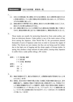
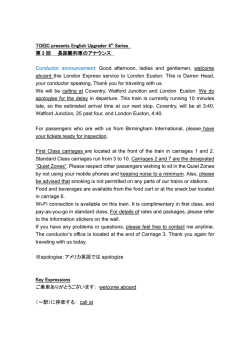
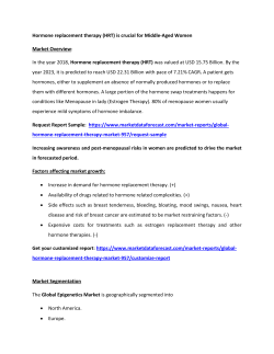
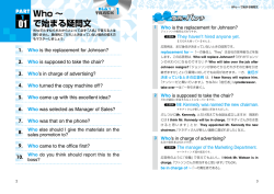
iP4700 / iP4760
SIMPLIFIED SERVICE MANUAL
1.
2.
LIST OF ERROR DISPLAY
ADJUSTMENT / SETTINGS
QY8-13CM-000
Rev.00
July 22, 2009
Canon Inc.
(1/24)
1.
LIST OF ERROR DISPLAY
1-1. Operator Call Errors (Alarm LED Lit In Orange)
Errors and warnings are displayed by the following ways:
- Operator call errors are indicated by the Alarm LED lit in orange, and messages are displayed
on the printer driver Status Monitor.
- Error codes (the latest 10 error codes at the maximum) are printed in the "operator call/service
call error record" area in EEPROM information print.
Buttons valid when an operator call error occurs:
- Power button:
To turn the printer off and on again.
- Resume/Cancel button: To cancel the job at error occurrence, and to clear the error.
LED
(Blinking in
orange)
2 times
Error
Error
code
No paper in the rear tray. [1000]
No CD / DVD tray
[1001]
No CD or DVD
[1002]
No paper in the cassette. [1003]
3 times
4 times
[1300]
[1303]
Solution
Remarks
Confirm that the rear tray is
selected as the paper source. Set
the paper in the rear tray, and
press the Resume/Cancel button.
Set the CD / DVD tray, and press
the Resume/Cancel button.
Set a CD or DVD in the CD / DVD
tray, and inset the CD / DVD tray
in the proper position. Then, press
the Resume/Cancel.
Confirm that the cassette is
selected as the paper source. Set
the paper in the cassette, and
press the Resume/Cancel button.
Remove the jammed paper, and
press the Resume/Cancel button.
Paper jam.
Paper jam in the rear
guide.
Paper jam in the under
guide.
The front door is closed.
[1250]
Open the front door.
Ink may have run out.
[1600]
Replace the applicable ink tank
and close the cover.
Ink tank not installed.
[1660]
Install the applicable ink tank(s)
properly, and confirm that the
LED's of all the ink tanks light in
red.
[1304]
(2/24)
The error is detected
at the start of printing
or during printing.
When the error is
cleared by pressing
the Resume/Cancel
button, ink may run out
during printing.
LED
(Blinking in
orange)
5 times
6 times
Error
8 times
9 times
Solution
Print head not installed, [1401]
or not properly installed.
Install the print head properly.
Faulty print head ID.
Print head temperature [1403]
sensor error.
Faulty EEPROM data of [1405]
the print head.
Inner cover error.
[1841*2,
1846*2,
1851*1,
1856*1]
[1850*1,
1855*1]
Re-set the print head. If the error
is not cleared, the print head may
be defective. Replace the print
head.
Time-out in CD / DVD
print operation.
7 times
Error
code
Multiple ink tanks of the
same color installed.
Ink tank in a wrong
position.
Warning: The ink
absorber becomes
almost full.
The connected digital
camera or digital video
camera does not support
Camera Direct Printing.
Remarks
Close the inner cover, and press
the Resume/Cancel button.
Open the inner cover, place the
CD-R tray and press
Resume/Cancel.
[1830*1] A prescribed period of time (12
minutes) has elapsed without any
printing since printing was
attempted. Press the
Resume/Cancel button to clear
the error.
[1487] Replace the wrong ink tank(s)
with the correct one(s).
[1680] Install the ink tank(s) in the correct
position.
[1700/ Replace the ink absorber, and
1701]
reset its counter. [See 2-2.
Adjustment / Settings, (4) Service
mode]
Pressing the Resume/Cancel
button will exit the error, and
enable printing without replacing
the ink absorber. However, when
the ink absorber becomes full, no
further printing can be performed
unless the applicable ink absorber
is replaced.
[2001] Remove the cable between the
camera and the printer.
(3/24)
The error “The ink
absorber becomes
almost full (service
call)” may occur soon.
LED
(Blinking in
orange)
10 times
Error
Automatic duplex
printing cannot be
performed.
Error
code
[1310]
11 times
Failed in automatic print [2500]
head alignment.
13 times
The remaining ink
amount unknown.
14 times
Ink tank not recognized. [1684]
15 times
Ink tank not recognized. [1682]
[1683]
Solution
Remarks
The paper length is not supported Data which was to be
printed on the back
for duplex printing.
Press the Resume/Cancel button side of paper at error
occurrence is not
to eject the paper being used at
printed.
error occurrence.
Data which was to be printed on
the back side of paper at error
occurrence is skipped (not
printed).
Press the Resume/Cancel button
to clear the error, then perform the
automatic print head again.
(In the iP4700 / iP4760, use Matte
Photo Paper MP-101.)
The ink tank installed
Replace the applicable ink tank
is judged to have once
with a new one. Printing with a
once-empty ink tank can damage been empty.
the printer.
To continue printing without
replacing the ink tank(s), press
the Resume/Cancel button for 5
sec. or longer to disable the
function to detect the remaining
ink amount. After the operation, it
is recorded in the printer
EEPROM that the function to
detect the remaining ink amount
was disabled.
A non-supported ink tank (an ink
tank that is sold in a different
region from where the printer was
purchased) is installed (the ink
tank LED is turned off). Install the
supported ink tanks.
A hardware error occurred in an
ink tank (the ink tank LED is
turned off). Replace the ink
tank(s).
(4/24)
LED
(Blinking in
orange)
Error
Error
code
16 times
No ink (no raw ink).
[1688]
19 times
Non-supported hub
[2002]
Solution
Replace the empty ink tank(s),
and close the scanning unit
(cover).
Printing with an empty ink tank
can damage the printer.
To continue printing without
replacing the ink tank(s), press
the Resume/Cancel button for 5
sec. or longer to disable the
function to detect the remaining
ink amount. After the operation, it
is recorded in the printer that the
function to detect the remaining
ink amount was disabled.
Remove the applicable USB hub
from the PictBridge (USB)
connector.
*1: Only for models supporting CD / DVD printing
*2: Only for models not supporting CD / DVD printing
(5/24)
Remarks
1-2. Service Call Errors (by Cyclic Blinking of Alarm and Power LEDs)
Cycles of
blinking of
Alarm and
Power LEDs
Error
2 times
Carriage error
3 times
Line feed error
4 times
Purge cam
sensor error
5 times
ASF (cam)
sensor error
6 times
Internal
temperature
error
Error
code
[5100]
Conditions
An error occurred in the
carriage encoder signal.
Solution
(Check points and replacement items)
1) Smearing or scratches on the carriage
slit film;
clean the timing slit film.
2) Foreign material or paper debris that
obstructs the carriage movement;
remove foreign material.
3) Ink tank conditions;
re-set the ink tanks.
4) Cable connection
5) Part replacement:
- Timing slit disk film
- Carriage unit
- Logic board
- Carriage motor
[6000] An error occurred in the LF 1) Smearing or scratches on the LF / EJ
encoder signal.
slit film;
clean the LF / EJ slit film.
2) Foreign material or paper debris in the
LF drive;
remove foreign material.
3) Cable connection
4) Part replacement:
- LF / EJ slit film
- LF / EJ timing sensor unit
- Paper feed roller unit
- Logic board
- Paper feed motor
[5C00] An error occurred in the
1) Foreign material or paper debris
purge unit.
around the purge drive system unit;
remove foreign material.
2) Cable connection
3) Part replacement:
- Purge drive system unit
- Logic board
[5700] An error occurred in the
1) Cable connection
ASF cam sensor.
2) Part replacement:
- ASF unit
- PE sensor board unit
- Logic board
[5400] The internal temperature is 1) Cable connection
not normal.
2) Part replacement:
- Carriage unit
- Logic board
- Print head
(6/24)
Cycles of
blinking of
Alarm and
Power LEDs
7 times
8 times
9 times
10 times
11 times
12 times
14 times
Error
code
Conditions
Ink absorber full [5B00,
5B01]
The ink absorber is
supposed to be full.
Error
Solution
(Check points and replacement items)
1) Ink absorber condition
2) Part replacement:
- Ink absorber kit
3) Ink absorber counter value in the
EEPROM;
reset the ink absorber counter.
Error codes:
5B00: Main ink absorber is
full (overseas).
5B01: Main ink absorber is
full (Japan).
Print head
[5200] The print head temperature 1) Print head condition
temperature rise
exceeded the specified
2) Head contact pin condition of the
error
value.
carriage unit
3) Cable connection
4) Part replacement:
- Print head
- Logic board
- Carriage unit
EEPROM error [6800, A problem occurred in
1) Part replacement:
[6801] reading from or writing to
- Logic board
the EEPROM.
VH monitor error [B200] The print head voltage is
1) Head contact pin condition of the
abnormal.
carriage unit
2) Cable connection (especially the
carriage FFC)
3) Part replacement:
- Print head and logic board
(Replace them at the same time.)
- Power supply unit
- Carriage unit
Carriage lift
[5110] The carriage did not move 1) Foreign material or paper debris that
mechanism
up or down properly.
obstructs the carriage movement;
error
remove foreign material.
2) Part replacement:
- Switch system unit
- Carriage unit
1) Foreign material or paper debris
APP position
[6A80] An error occurred in the
around the purge drive system unit;
error
APP motor.
remove foreign material, and
APP sensor
[6A90] An error occurred during
confirm that the ink absorber right
error
paper feeding or paper
beneath the purge drive system unit
ejection.
stays in place and does not contact
the unit.
2) Foreign material or paper debris
around the ASF unit;
remove foreign material.
3) Cable connection
4) Part replacement:
- Purge drive system unit
- Logic board
(7/24)
Cycles of
blinking of
Alarm and
Power LEDs
Error
Error
code
Conditions
Paper feed cam [6B10] An error occurred in the
sensor error
paper feed cam sensor
during paper feeding from
the cassette, or the paper
absorbing a large amount
of ink jammed in the PF
rear guide.
15 times
USB Host VBUS [9000]
overcurrent
Pump roller
[5C20]
sensor error
The USB Host VBUS is
overloaded.
The pump roller position
cannot be detected.
17 times
Paper eject
encoder error
Paper eject encoder error
19 times
Ink tank position [6502]
sensor error
20 times
Other errors
21 times
Drive switch
error
16 times
[6010]
None of the ink tank
position is detected.
[6500]
An unidentified error
occurred.
[C000] Drive was not switched
properly.
(8/24)
Solution
(Check points and replacement items)
1) Jammed paper in the PF rear guide
(when a large amount of ink was
absorbed in the paper);
remove the jammed paper and
foreign material.
2) Foreign material or paper debris in the
cassette or in the PF rear guide;
remove foreign material.
3) Part replacement:
- PF pick-up unit
- Logic board
1) Part replacement:
- Logic board
1) Cable connection
2) Part replacement:
- Purge drive system unit
1) Smearing or scratches on the LF / EJ
slit film;
clean the LF / EJ slit film.
2) Foreign material or paper debris in the
paper path;
remove foreign material.
3) Cable connection
4) Part replacement:
- LF / EJ slit film
- LF / EJ timing sensor unit
- Platen unit
- Logic board
- Paper feed motor
1) Ink tank position;
confirm the ink tank position.
2) Re-set or replacement of ink tanks
3) Cable connection
4) Part replacement:
- Spur unit
- Logic board
1) Part replacement:
- Logic board
1) Foreign material or paper debris in the
drive switch area;
remove foreign material,
confirm the ink tank conditions, or
re-set the ink tanks properly.
2) Part replacement:
- Purge drive system unit
- ASF unit
- Carriage unit
Cycles of
blinking of
Alarm and
Power LEDs
23 times
Error
Error
code
Conditions
Valve cam
sensor error
Solution
(Check points and replacement items)
[6C10] The valve cam sensor was 1) Foreign material or paper debris
faulty at power-on or when
around the purge drive system unit;
purging was attempted.
remove foreign material.
2) Cable connection
3) Part replacement:
- Purge drive system unit
- Logic board
Note: Before replacement of the logic board ass'y, check the ink absorber counter value (by service
test print or EEPROM information print). If the counter value is 7% or more, also replace the ink
absorber kit when replacing the logic board ass'y. If the counter value is less than 7%, register
the current ink absorber counter value to the replaced new logic board instead.
(9/24)
2.
ADJUSTMENT / SETTINGS
2-1. Service Mode
< Service mode operation procedures >
Use the Service Tool on the connected computer.
1)
Start the printer in the service mode.
i.
With the printer power turned off, while pressing the Resume/Cancel button, press and hold
the Power button. (DO NOT release the buttons).
ii. When the Power LED lights in green, while holding the Power button, release the
Resume/Cancel button. (DO NOT release the Power button.)
iii. While holding the Power button, press the Resume/Cancel button 2 times, and then release
both the Power and Resume/Cancel buttons. (Each time the Resume/Cancel button is
pressed, the Alarm and Power LEDs light alternately, Alarm in orange and Power in green,
starting with Alarm LED.)
iv. When the Power LED lights in green, the printer is ready for the service mode operation.
2)
Start the Service Tool on the connected computer.
i.
When a button is clicked in the Service Tool dialog box, that function is performed. During
operation of the selected function, all the Service Tool buttons are dimmed and inactive.
ii
When the operation is completed, "A function was finished." is displayed, and another
function can be selected.
iii If a non-supported function is selected, "Error!" is displayed. Click OK in the error message
dialog box to exit the error.
< Service Tool Functions >
V.1.05
(10/24)
No.
Name
Function
Remarks
(1)
Test Print
Service test print
Paper (2 sheets) will feed from the rear tray.
Service test print items:
- Model name
- ROM version
- USB serial number
- EEPROM information
- Process inspection information
- Barcode (model name + destination + printer
serial number)
- Ink system function check result
- CD / DVD sensor check result (printed on the
second sheet)
(2)
EEPROM
EEPROM information print The dialog box opens to select the paper source.
Select Rear tray or Cassette, and click OK.
EEPROM information print items:
- Model name
- ROM version
- Ink absorber counter value (ink amount in the ink
absorber)
- Print information
- Error information, etc.
(3)
CD-R
CD-R check pattern print
For refurbishment use. Not used in servicing.
(4)
LF / EJECT
LF / Eject correction
pattern print
Perform LF / Eject correction only when streaks or
uneven printing occurs after the repair.
See “LF / Eject correction” below for details.
(5)
Nozzle Check
Nozzle check pattern print The dialog box opens to select the paper source.
Select Rear tray or Cassette, and click OK.
(6)
Integration
Paper will feed from the rear tray.
Successive print of (1)
service test pattern, (2)
EEPROM information, and
(5) nozzle check pattern
(7)
Left Margin
Left margin pattern print
Not used.
(8)
Deep Cleaning
Print head deep cleaning
Cleaning of both Black and Color at the same
time.
(9)
Main
Main ink absorber counter Set a sheet of A4 or Letter sized plain paper. After
resetting
the ink absorber counter is reset, the counter value
is printed automatically.
Platen
Platen ink absorber
counter resetting
Not used.
(11/24)
No.
Name
Function
Remarks
(10) EEPROM Clear
EEPROM initialization
The following items are NOT initialized, and the
shipment arrival flag is not on:
- USB serial number
- Destination settings
- Record of ink absorber counter resetting and
setting
- Record of repair at the production site
- CD / DVD print position correction value
- LF / Eject correction values
- Left margin correction value
- Production site E-MIP correction value and
enabling of it
- Endurance correction value and enabling of it
- Record of disabling the function to detect the
remaining ink amount
- Ink absorber counter value (ink amount in the ink
absorber)
(11) Panel Check
Button and LCD test
Not used.
(12) Set Destination
Destination settings
Select the destination, and click Set.
ASA, AUS, BRA, CHN, CND, EUR, JPN, KOR,
LTN, TWN, USA
(13) CD-R Correction
CD / DVD print position
correction (X and Y
direction)
Also for printing of the CD / DVD check pattern in
refurbishment operation.
The reference center in the X direction and in the
Y direction can be adjusted respectively.
(Adjustable range between -1.0 mm to +1.0 mm, in
0.1 mm increment)
(14) LF / EJECT
Correction
LF / Eject correction value Set the correction value according to the result of
setting
(4) LF / Eject correction pattern print.
See " LF / Eject correction " below for details.
(15) Left Margin Correction Left margin correction
value setting
Not used.
(16) Ink Absorber Counter Ink absorber counter
setting
See " Ink absorber counter setting " below.
(17) Wetting Liquid
Counter
Not used.
Wetting liquid counter
setting
< LF / Eject correction >
After replacement of the feed roller, platen unit, LF / Eject encoder, encoder film, or logic board in
repair servicing or in refurbishment operation, perform the adjustment to maintain the optimal print
image quality.
1) Print the LF / Eject correction pattern.
Click LF/EJECT of the Service Tool on the connected computer, select the paper source and the
paper type, and print the pattern. 5 sheets of paper will be used for the pattern printing.
- Paper source: Select either Rear tray or Cassette.
- Media type:
Select one from HR-101, GF-500/Office Planner, HP Bright White, and
Canon Extra/STEINBEIS.
(12/24)
2) When printing is finished, the printer returns to be ready for selection of another function.
3) In the printout, determine the Pattern No. in which streaks or lines are the least noticeable for the
LF check pattern and the Eject check pattern respectively. (LF Pattern No. 0 to 4, Eject Pattern
No. 0 to 4)
4) In the LF/EJECT Correction section of the Service Tool, select the Pattern No. (from 0 to 4)
determined in step 3) for LF and EJECT respectively, and click Set.
5) The selected LF and Eject correction values are written to the EEPROM, making the E-MIP
correction value (which was set at shipment from the production site) invalid.
Note: At the production site, the E-MIP correction, which is equivalent to the LF / Eject correction,
is performed using the special tool, and the E-MIP correction value is written to the EEPROM
as the valid data.
When LF / Eject correction is performed, the LF / Eject correction values become valid
instead of the E-MIP correction value (thus, in the initial EEPROM information print, "LF = *"
and "EJ = *" are printed, but the selected values are printed after the LF / Eject correction).
<Ink absorber counter setting>
Set the ink absorber counter value to a new EEPROM after the logic board is replaced in servicing.
1) Before replacement of the logic board, check the ink absorber counter value in EEPROM
information print.
2) After replacement of the logic board, the ink absorber counter value should be set in the service
mode using the Service Tool.
In the Ink Absorber Counter section of the Service Tool, select Main from the Absorber
pull-down menu.
From the Counter Value(%) pull-down menu, select the value (in 10% increments) which is the
closest to the actual counter value confirmed before replacement of the logic board, and click
Set.
3) Print EEPROM information to confirm that the value is properly set to the EEPROM.
<CD / DVD print position correction>
Set the CD / DVD print position value to a new EEPROM after the logic board is replaced in
servicing.
Note: For solution of user complaints, this function can be used, however, use of the application
software is recommended to adjust the CD / DVD print position.
(13/24)
1) Before replacement of the logic board, check the CD / DVD print position value in EEPROM
information print.
2) After replacement of the logic board, set the print position value in CD-R Correction of the
Service Tool.
3) If EEPROM information is not available before replacement of the logic board due to logic board
failure, etc., click CD-R in the Service Tool to print the CD-R check pattern, and confirm that the
intersection of the axes Y and X is at the center of the CD / DVD.
(14/24)
2-2. User Mode
Function
Procedures
Remarks
Nozzle check pattern
printing
Perform from the printer driver
Maintenance tab, or see
"Standalone printer operation"
below.
Set a sheet of plain paper (A4 or Letter) in
the cassette, or the rear tray if selected.
Print head manual
cleaning
Perform from the printer driver
Maintenance tab.
- Cleaning of both Black and Color
- Cleaning Black or Color separately
Unclogging of the print head nozzles, and
maintenance to keep the print head
conditions good.
If there is a missing portion or white streaks
in the nozzle check pattern printout,
perform this cleaning.
Print head deep
cleaning
Perform from the printer driver
Maintenance tab.
If print head cleaning is not effective,
perform this cleaning. Since the deep
cleaning consumes more ink than regular
cleaning, it is recommended to perform
deep cleaning only when necessary.
Automatic print head
alignment
Perform from the printer driver
Maintenance tab.
Set 1 sheet of A4 Matte Photo Paper
(MP-101) in the rear tray.
If automatic alignment is not effective,
perform manual print head alignment.
Manual print head
alignment
Perform from the printer driver
Maintenance tab.
Set 3 sheets of plain paper (A4 or Letter) in
the cassette, or the rear tray if selected.
Print head alignment
value printing
Perform from the printer driver
Maintenance tab.
Confirmation of the current print head
alignment values.
Paper feed roller
cleaning
Perform from the printer driver
Maintenance tab.
The paper feed rollers of the selected
paper source (the rear tray or the cassette)
rotate while being pushed to the paper
lifting plate. Since the rollers will wear out in
this cleaning, it is recommended that you
perform this only when necessary.
Bottom plate cleaning
Perform from the printer driver
Maintenance tab, or see
"Standalone printer operation"
below.
Cleaning of the platen ribs when the back
side of paper gets smeared.
Fold a sheet of plain paper (A4 or Letter) in
half crosswise, then unfold and set it in the
rear tray with the folded ridge facing down.
(No paper feeding from the cassette)
< Standalone printer operation >
1) Turn on the printer in the user mode.
2) Press and hold the Resume/Cancel button until the Power LED blinks in green the specified
number of times listed in the table below, and release it. The operation starts.
Power
LED
(blinking in
green)
1 time
2 times
Operation
Manual print head cleaning
Nozzle check pattern printing
Remarks
Set a sheet of plain paper (A4 or Letter) in the cassette.
(15/24)
Power
LED
(blinking in
green)
5 times
Operation
Remarks
Bottom plate cleaning
2-3. Special Notes on Assembling
(1)
External housing removal
1) Remove the cassette.
2)
Remove the paper support unit and the access cover.
< While pushing the both sides of the paper support so that the center will warp slightly, release the
left and right bosses. >
3)
Remove the main case covers L and R.
< While inserting a flat-blade screwdriver, etc. through into a space under the main case cover; and
pressing the claw downward, slide the main case cover toward the front side of the printer. >
(16/24)
4)
Remove the side cover L.
5)
Remove the side cover R.
(17/24)
6)
Remove the front door unit.
< While slightly warping the center of the paper output tray downward, release the left and right
bosses. >
7)
Remove the panel cover unit (1 screw).
(18/24)
8)
Remove the main case unit.
(19/24)
(2)
Notes on Service Part Replacement (and Disassembling / Reassembling)
Service part
Logic board ass'y
Absorber kit
Notes on replacement*1
Adjustment / settings
Operation check
- Before removal of the
logic board ass'y,
remove the power cord,
and allow for approx. 1
minute (for discharge of
capacitor's accumulated
charges), to prevent
damages to the logic
board ass'y.
- Before replacement,
check the ink absorber
counter value (by service
test print or EEPROM
information print).
After replacement:
1) Initialize the EEPROM.
2) Set the ink absorber counter
value.
3) Set the destination in the
EEPROM.
4) Correct the CD / DVD and
automatic print head
alignment sensors.
5) Check the ink system
function.
6) Perform LF / Eject
correction (only when
streaks or uneven printing
occurs).
Perform 1 to 6 in the service
mode.
7) Perform print head
alignment in the user mode.
After replacement:
1) Reset the ink absorber
counter.
- EEPROM information print
- Service test print
- Printing via USB connection
- Direct printing from a digital
camera (PictBridge)
Carriage unit
- Ink absorber counter
volume print (After the ink
absorber counter is reset,
the counter value is printed
automatically.)
- Service test print (Confirm
CD / DVD and automatic
print head alignment sensor
correction, and ink system
function.)
At replacement:
1) Before removal of the
carriage rail, mark the
carriage rail position.
2) Apply grease to the sliding
portions of the carriage rail.
[See 2-2. Adjustment /
Settings, (2) Grease
application]
3) Check the ink system
function.
4) Perform print head
alignment in the user mode.
- EEPROM information print
Switch system unit - The red screws securing At replacement:
the paper feed motor are 1) Adjust the paper feed motor. - Service test print
allowed to be loosened
only for paper feed motor
Paper feed motor
replacement. (DO NOT
loosen them in any other
cases.)
- EEPROM information print
Platen unit
After replacement:
- Service test print
1) Perform LF / Eject
correction in the service
mode (only when streaks or
uneven printing occurs).
(20/24)
Service part
Spur unit
Notes on replacement*1
- DO NOT contact the
spur edges.
Purge drive system
unit
Carriage rail and
main chassis
Idler pulley parallel
pin
Easy-Scroll Wheel
base
APP code wheel
gear shaft
Timing slit strip film - Upon contact with the
film, wipe the film with
ethanol.
Timing slit disk
- Confirm no grease is on
feed film
the film. (Wipe off any
Timing slit disk
grease thoroughly with
eject film
ethanol.)
- Do not bend the film.
Print head
*1:
Adjustment / settings
After replacement:
1) Check the ink system
function.
2) Perform LF / Eject
correction in the service
mode (only when streaks or
uneven printing occurs).
After replacement:
1) Confirm the purging
operation and the printer
operation.
At replacement:
1) Apply grease to the sliding
portions.
Operation check
- EEPROM information print
- Service test print
- Service test print
- Service test print
- EEPROM information print
After replacement:
- Service test print
1) Perform print head
alignment in the user mode.
2) Perform LF / Eject
correction in the service
mode (only when streaks or
uneven printing occurs).
- Service test print
After replacement:
1) Perform print head
alignment in the user mode.
General notes:
- Make sure that the flexible cables and wires in the harness are in the proper position and
connected correctly.
- Do not drop the ferrite core, which may cause damage.
- Protect electrical parts from damage due to static electricity.
- Before removing a unit, after removing the power cord, allow the printer to sit for approx. 1 minute
(for capacitor discharging to protect the logic board ass'y from damages).
- Do not touch the timing slit strip film, timing slit disk feed film, and timing slit disk eject film. No
grease or abrasion is allowed.
- Protect the units from soiled with ink.
- Protect the housing from scratches.
- For the the iP4700 / iP4760 automatic print head alignment, use Matte Photo Paper (MP-101) to
ensure alignment accuracy.
- Exercise caution with the screws, as follows:
i. The screws of the paper feed motor may be loosened only at replacement of the paper
feed motor unit (DO NOT loosen them in other cases).
ii. Before loosening the 3 screws that fix the carriage rail to the main chassis, mark the
screw positions so that the carriage rail will be re-attached to the main chassis in its
original position.
(21/24)
(3)
Paper feed motor adjustment
1) When attaching the motor, fasten the screws so that the belt is properly stretched (in the
direction indicated by the blue arrow in the photo below).
2) After replacement, be sure to perform the service test print, and confirm that no strange noise or
faulty print operation (due to dislocation of the belt or gear, or out-of-phase motor, etc.) occurs.
Caution: The screws securing the paper feed motor may be loosened only at replacement of the
paper feed motor unit. DO NOT loosen them in other cases.
(4)
Ink absorber counter setting
Before replacement of the logic board, check the ink absorber counter value, and register it to the
replaced new logic board. (The value can be set in 10% increments.)
In addition, according to the ink absorber counter value, replace the ink absorber (ink absorber kit).
When the ink absorber is replaced, reset the applicable ink absorber counter (to 0%).
(22/24)
2-4. Grease application
No
1
2
3
4
5
6
7
Part name
Where to apply grease /
oil
The surface where the
carriage unit slides
The surface where the
Carriage rail
carriage unit slides
The surface where the
Carriage rail
carriage unit slides
The surface where the
Carriage rail
carriage unit slides
The surface where the
Main chassis
carriage unit slides
The pin surface which
Parallel pin
contacts the idler pulley
hole
APP code wheel gear
APP code wheel
sliding portion (the entire
gear shaft
surface)
Carriage rail
Drawing
No.
Grease
Grease
amount (mg)
Number of
drops x
locations
(1)
Floil KG107A
270 to 330
---
(2)
Floil KG107A
18 to 36
1x2
(3)
Floil KG107A
360 to 440
---
(4)
Floil KG107A
360 to 440
---
(5)
Floil KG107A
230 to 290
---
(6)
Floil KG107A
9 to 18
1x1
(7)
Floil KG107A
9 to 18
1x1
1 drop = 9 to18 mg
(23/24)
2-5. Notes on Transportation
This section describes the procedures for transporting the printer for returning after repair, etc.
1) In the service mode, press the Power button to finish the mode, and confirm that the paper
lifting plate of the rear tray is raised.
2) Keep the print head and ink tanks installed in the carriage. See Caution (a) below.
3) Turn off the printer to securely lock the carriage in the home position. (When the printer is
turned off, the carriage is automatically locked in place.) See Caution (b) below.
Caution:
a.
b.
Note:
If the print head is removed from the printer and left alone by itself, ink (the
pigment-based black ink in particular) is likely to dry. For this reason, keep the print
head installed in the printer even during transportation.
Securely lock the carriage in the home position, to prevent the carriage from moving
and applying stress to the carriage flexible cable, or causing ink leakage, during
transportation.
If the print head must be removed from the printer and transported alone, attach the
protective cap (used when the packing was opened) to the print head (to protect the print
head face from damage due to shocks).
(24/24)
© Copyright 2026 Paperzz