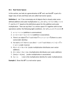
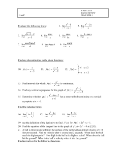
State Space Model for Autopilot Design of Aerospace
Vehicles
Farhan A. Faruqi
Weapons Systems Division
Defence Science and Technology Organisation
DSTO-TR-1990
ABSTRACT
This report is a follow on to the report given in DSTO-TN-0449 and considers the derivation of
the mathematical model for aerospace vehicles and missile autopilots in state space form. The
basic equations defining the airframe dynamics are non-linear, however, since the nonlinearities are “structured” (in the sense that the states are of quadratic form) a novel approach
of expressing this non-linear dynamics in state space form is given. This should provide a
useful way to implement the equations in a computer simulation program and possibly for
future application of non-linear analysis and synthesis techniques, particularly for autopilot
design of aerospace vehicles executing high g-manoeuvres.
This report also considers a locally linearised state space model that lends itself to better
known linear techniques of the modern control theory. A coupled multi-input multi-output
(MIMO) model is derived suitable for both the application of the modern control techniques
as well as the classical time-domain and frequency domain techniques. The models developed
are useful for further research on precision optimum guidance and control. It is hoped that the
model will provide more accurate presentations of missile autopilot dynamics and will be
used for adaptive and integrated guidance & control of agile missiles.
RELEASE LIMITATION
Approved for public release
Published by
DSTO Defence Science and Technology Organisation
PO Box 1500
Edinburgh, SA 5111 Australia
Telephone: (08) 8259 7245
Fax: (02) 8259 6964
© Commonwealth of Australia 2007
AR-013-894
March 2007
APPROVED FOR PUBLIC RELEASE
State Space Model for Autopilot Design of
Aerospace Vehicles
Executive Summary
Requirements for next generation guided weapons and other aerospace vehicles,
particularly with respect to their capability to engage high speed, highly agile targets and
achieve precision end-game trajectory, have prompted a revision of the way in which the
guidance and autopilot design is undertaken. This report considers the derivation of the
mathematical models for aerospace vehicles and missile autopilots in state space form.
The basic equations defining the airframe dynamics are non-linear, however, since the
non-linearities are “structured” (in the sense that the states are of quadratic form) a novel
approach of expressing this non-linear dynamics in state space form is given. This should
provide a useful way to implement the equations in a computer simulation program and
possibly for future application of non-linear analysis and synthesis techniques.
This report which is a follow on report to DSTO-TN-0449, also considers a locally
linearised state space model that lends itself to better known linear techniques of the
modern control theory. A coupled multi-input multi-output (MIMO) model is derived
suitable for both the application of the modern control techniques as well as the classical
time-domain and frequency domain techniques. The models developed are useful for
further research on precision optimum guidance and control. It is hoped that the model
will provide more accurate presentations of aerospace vehicles autopilot dynamics and
will be used for adaptive and integrated guidance & control of agile missiles and other
aerospace vehicles that do not necessarily have symmetric cruciform airframes.
Authors
Dr. Farhan A. Faruqi
Weapons Systems Division
Farhan A. Faruqi received B.Sc.(Hons) in Mechanical Engineering
from the University of Surrey (UK), 1968; M.Sc. in Automatic
Control from the University of Manchester Institute of Science and
Technology (UK), 1970 and Ph.D from the Imperial College, London
University (UK), 1973. He has over 20 years experience in the
Aerospace and Defence Industry in UK, Europe and the USA. Prior
to joining DSTO in January 1999 he was an Associate Professor at
QUT (Australia) 1993-98. His research interests include: Missile
Navigation, Guidance and Control, Target Tracking and Precision
Pointing Systems, Strategic Defence Systems, Signal Processing, and
Optoelectronics.
Contents
1. INTRODUCTION ............................................................................................................... 1
2. STATE SPACE AERODYNAMICS MODEL ................................................................. 2
2.1 Nonlinear Airframe Model ..................................................................................... 2
2.2 Body Acceleration Model ........................................................................................ 6
2.3 Accelerometer Dynamics Model............................................................................ 7
2.4 Gyro Dynamics Model............................................................................................. 9
2.5 Actuation Servo Model .......................................................................................... 10
2.6 Overall Nonlinear (Quadratic) Airframe Model including IMU .................. 12
2.7 The Measurement Model ...................................................................................... 12
3. LINEARISED STATE SPACE AIRFRAME MODEL ................................................. 13
3.1 Linearised Measurement Model .......................................................................... 15
4. CONCLUSIONS ................................................................................................................ 16
5. REFERENCES..................................................................................................................... 17
APPENDIX A:
...................................................................................................................... 19
A.1. Non-linear (Quadratic) Airframe and IMU Dynamics............ 19
A.1.1
Body Acceleration Model .............................................. 22
A.1.2
Accelerometer and Gyro Dynamics............................. 24
A.1.3
A.1.3 Accelerometer Dynamics..................................... 25
A.1.4
Gyro Dynamics................................................................ 27
A.1.5
Actuation Servo Model .................................................. 29
A.1.6
Non-linear Airframe, IMU and Actuator Dynamic .. 30
A.1.7
Measurement Model ...................................................... 31
A.2. Linearised Airframe, Actuation and IMU Dynamics .............. 32
A.2.1
Linearised Aerodynamic Forces and Moments......... 32
A.2.2
Linearisation of the Quadratic State Vector .............. 34
A.2.3
Linearised Airframe, IMU, Actuator Model .............. 35
A.3. Decomposed State Space Models................................................ 38
A.3.1
Nonlinear Model:............................................................ 38
A.3.2
Linearised Model: ........................................................... 38
DSTO-TR-1990
1. Introduction
Requirements for next generation guided weapons, particularly with respect to their
capability to engage high speed, highly agile targets and achieve precision end-game
trajectory, have prompted a revision of the way in which the guidance and autopilot design
are undertaken. Integrating the guidance and control function is a synthesis approach that is
being pursued as it allows the optimisation of the overall system performance. This approach
requires a more complete representation of the airframe dynamics and the guidance system.
The use of state space model allows the application of modern control techniques such as the
optimal adaptive control and parameter estimation techniques [10] to be utilised. In this report
we derive the autopilot model that will serve as a basis for an adaptive autopilot design and
allow further extension of this to integrated guidance and control system design.
Over the years a number of authors [1-3, 6-9] have considered modelling, analysis and design
of autopilots for atmospheric flight vehicles including guided missiles. In the majority of the
published work on autopilot analysis and design, locally linearised versions of the model with
decoupled airframe dynamics have been considered. This latter simplification arises out of the
assumption that the airframe and its mass distribution are symmetrical about the body axes,
and that the yaw, pitch and roll motion about the equilibrium state remain “small”. As a
result, many of the autopilot analysis and design techniques, considered in open literature,
use classical control approach, such as: single input/single output transfer-functions
characterisation of the system dynamics, Bode, Nyquist, root-locus and transient -response
analysis and synthesis techniques [5, 7]. These techniques are valid for a limited set of flight
regimes and their extension to cover a wider set of flight regimes and airframe configurations
requires autopilot gain and compensation network switching.
With the advent of fast processors it is now possible to take a more integrated approach to
autopilot design. Modern optimal control techniques allow the designer to consider autopilots
with high-order dynamics (large number of states) with multiple inputs/outputs and to
synthesise controllers such that the error between the demanded and the achieved output is
minimised. Moreover, with real-time mechanisation any changes in the airframe
aerodynamics can be identified (parameter estimation) and compensated for by adaptively
varying the optimum control gain matrix. This approach should lead to missile systems that
are able to execute high g-manoeuvres (required by modern guided weapons), adaptively
adjust control parameters (to cater for widely varying flight profiles) as well as account for
non-symmetric airframe and mass distributions. Typically, for a missile autopilot, the input is
the demanded control surface deflection and outputs are the achieved airframe (lateral)
accelerations and body rates measured about the body axes. Other input/output variables
(such as: the flight path angle and angle rate or the body angles) can be derived directly from
lateral accelerations and body rates.
This report considers the derivation of the mathematical model for a missile autopilot in state
space form. The basic equations defining the airframe dynamics are non-linear, however,
since the nonlinearities are “structured” (in the sense that the states are of quadratic form) a
novel approach of expressing this non-linear dynamics in state space form is given. This
should provide a useful way to implement the equations in a computer simulation program
1
DSTO-TR-1990
and possibly for future application of non-linear analysis and synthesis techniques. Detailed
consideration of the quadratic/bilinear type of dynamic systems is given in [4].
This report which is a follow on report from the previous report [1,2], also considers a locally
linearised state space model that lends itself to better known linear techniques of the modern
control theory. A coupled multi-input multi-output (MIMO) model is derived suitable for
both the application of the modern control techniques as well as the classical time-domain and
frequency domain techniques. For sake of clarity, Figure 2.1 is a symmetric cruciform missile,
however the models developed are valid for non axis-symmetric aerospace vehicles.
Tables A-1.1 to A-1.3 contain the various aerodynamic derivatives and coefficients.
2. State Space Aerodynamics Model
The airframe, actuation and sensor measurement equations have been derived in detail in
Appendix A in this section we give the main results that will be used for matrix based
computation of the state space model.
2.1 Nonlinear Airframe Model
Conventions and notations for vehicle body axes systems as well as the forces, moments and
other quantities are shown in Figure 2.1 and defined in Table 2.1.
T
Ixx, Lp
Iyy, Mq
Izz, Nr
Figure 2.1 Motion variable notations
The variables shown in Figure 2.1 are defined as:
m - mass of a vehicle.
2
σ
DSTO-TR-1990
α - incidence in the pitch plane.
β - incidence in the yaw plane.
λ - incidence plane angle.
σ - total incidence, such that: tan α = tan σ cos λ, and tan β = tan σ sin λ.
T – thrust.
Table 2.1: Motion variables
Vehicle Body Axes System
Angular rates
Component of vehicle velocity along each axis
Component of aerodynamic forces acting on vehicle along
each axis
Moments acting on vehicle about each axis
Moments of inertia about each axis
Products of each inertia
Longitudinal and lateral accelerations
Euler angles
Gravity along each axis
Vehicle thrust along the body axis
Roll
axis
p
u
X
Pitch
axis
q
v
Y
Yaw
axis
r
w
Z
L
Ixx
Iyz
ax
M
Iyy
Izx
ay
N
Izz
Ixy
az
φ
θ
ψ
gx
T
gy
gz
Tail Control Configuration:
We shall use the following notation: ξ - aileron deflection; η - elevator deflection; ς - rudder
deflection. Figure 2.2 defines the control surface convention. Here the control surfaces are
numbered as shown and the deflections ( δ 1 , δ 2 , δ 3 , δ 4 ) are taken to be positive if clockwise,
looking outwards along the individual hinge axis. Thus, Aileron deflection:
1
1
ξ = ( δ 1 + δ 2 + δ 3 + δ 4 ) , if all four control surfaces are active; or ξ = ( δ 1 + δ 3 ) , or
4
2
1
ξ = ( δ 2 + δ 4 ) if only two surfaces are active. Positive control defection (ξ) causes negative
2
1
roll. Elevator deflection: η = ( δ 1 − δ 3 ) . Positive control deflection (η) causes negative pitch.
2
1
Rudder deflection: ζ = ( δ 2 − δ 4 ) . Positive control deflection (ζ) causes negative yaw.
2
3
DSTO-TR-1990
+δ4
+δ3
+δ1
+δ2
Figure 2.2 Control surfaces seen from the rear of a missile
Canard Control Configuration:
For a canard configuration, same convention will be used for control surface deflections;
however, it is noted that the force and moment coefficients will have opposite signs. Canard
control is generally not used for roll control.
Euler Equations of Motion
The six equations of motion for a body with six degrees of freedom may be written as [1-3]:
m ( u& + wq − vr ) = X + T + g x m
m ( v& + ur − wp ) = Y + g y m
(2-1)
(2-2)
m ( w& − uq + vp ) = Z + g x m
I xx p& − ( I yy − I zz )qr + I yz ( r 2 − q 2 ) − I zx ( pq + r& ) + I xy ( rp − q& ) = L
(2-3)
I yy q& − ( I zz − I xx )rp + I zx ( p 2 − r 2 ) − I xy ( qr + p& ) + I yz ( pq − r& ) = M
(2-5)
I zz r& − ( I xx − I yy ) pq + I xy ( q 2 − p 2 ) − I yz ( rp + q& ) + I zx ( qr − p& ) = N
(2-6)
(2-4)
d
- is the derivative operator.
dt
Based on the Euler equations above, the nonlinear (quadratic) airframe state space model is
given by (see equations A-1.1 to A-1.5):
Here ( ⋅ ) =
d [1]
x = [F0 ] x [32 ] + [G0 ] u[31]+ g [1]
dt 3
4
(2-7)
DSTO-TR-1990
Where:
⎡ x [1] ⎤
⎢ 1 ⎥
x [31] = ⎢ − − ⎥ = [u v
⎢ x [1] ⎥
⎣⎢ 2 ⎦⎥
w |
⎡ x [2 ] ⎤
⎢ 1 ⎥
x [32 ] = ⎢ − − ⎥ = uq ur
⎢ x [2 ] ⎥
⎣⎢ 2 ⎦⎥
state vector.
[
p q r ]T : is a 6x1 linear-state vector.
vp vr
⎡ u[1] ⎤
1 ⎥
~ ~ ~
[
1] ⎢
u3 = ⎢ − − ⎥ = X + T Y
⎢ u[1] ⎥
⎣⎢ 2 ⎦⎥
and moments.
[
p2
wp wq |
~
Z | L M
N
pq
pr q 2
qr
r2
] : is a 12x1 quadraticT
]T : is 6x1 a vector function of control inputs, forces
⎡ g ⎤
⎢
⎥
g [1] = ⎢ − − ⎥ = [g x g y g z 0 0 0 ]T : is the 6x1 gravity (or disturbance) vector.
⎢0 3× 1 ⎥
⎣
⎦
⎡ [C ] |
[03×6 ] ⎤⎥
⎢ 0
[F0 ] = ⎢ − − − | − − − − − − ⎥ : is a 6x12 state-coefficient matrix.
⎢[0 ] | [ A ]− 1 [B ]⎥
0
0 ⎦⎥
⎣⎢ 3×6
⎡ [I
]
⎢ 3× 3
[G0 ] = ⎢ − − −
⎢ [0 ]
⎢⎣ 3× 3
⎡ I xx
[A0 ] = ⎢⎢− I xy
⎢− I
⎣ zx
⎡ 0
[B0 ] = ⎢⎢− I zx
⎢ I
⎣ xy
|
[03× 3 ] ⎤⎥
− − − ⎥ : is a 6x6 input-coefficient matrix.
| [ A0 ]− 1 ⎥⎥
⎦
|
− I xy
I yy
− I yz
− I zx ⎤
⎥
− I yz ⎥ : is a 3x3 matrix.
I zz ⎥⎦
I zx
− I yz
I xx − I yy
(
)
− I xy
I yz
(I yy − I zz )
I yz
0
− I xy
I xy
− I zx
(I zz − I xx )
− I yz ⎤
⎥
I zx ⎥
0 ⎥⎦
: is a 3x6 matrix.
5
DSTO-TR-1990
0 1 0 − 1⎤
⎡0 0
⎢
[C0 ] = ⎢0 − 1 0 0 1 0 ⎥⎥ : is a 3x6 matrix.
⎢⎣ 1 0 - 1 0 0 0 ⎥⎦
Subscripts under [I] and [0] matrices denote the matrix dimensions. Generally, not all state
variables in the state equation are accessible or measurable. The vehicle angular rate
components (roll rate p, pitch rate q, and yaw rate r) and the acceleration components (ax, ay,
az) are commonly available and can be measured using the IMU.
2.2 Body Acceleration Model
Equations for the vehicle actual body accelerations and body rates are derived in Appendix A
equations (A-1.6) to (A-1.11). These equations allow position offsets from c.g for observing the
body accelerations. The acceleration components at point O (where O is at a distance of dx, dy
and dz from the central point of gravity, c.g., along x-, y- and z-axis, respectively), may be
written as:
a x = u& + qw − rv − d x ( q 2 + r 2 ) + d y ( pq − r& ) + d z ( pr + q& )
~ ~
= X + T + g x − d x ( q 2 + r 2 ) + d y ( pq − r& ) + d z ( pr + q& )
(2-8)
a y = v& + ru − pw + d x ( pq + r& ) − d y ( p 2 + r 2 ) + d z ( qr − p& )
~
= Y + g y + d x ( pq + r& ) − d y ( p 2 + r 2 ) + d z ( qr − p& )
(2-8)
a z = w& + pv − qu + d x ( pr − q& ) + d y ( qr + p& ) − d z ( p 2 + q 2 )
~
= Z + g z + d x ( pr − q& ) + d y ( qr + p& ) − d z ( p 2 + q 2 )
(2-9)
After some matrix manipulations, the body acceleration model may be written as (see
equations (A-1.6) to (A-1.11):
y [1] = [J 0 ] x [31] + [K 0 ] x [32 ] +[L0 ] u[31] +[M 0 ] g [1]
3
Where:
[
y [1] = a x
1
ay
]
a z T : is a 3x1 body acceleration vector.
y [1] = x [21] = [ p q r ]T : is a 3x1 body rate vector
2
[
y [1] = y [1] |
3
6
1
]
y [1] T : is a 6x1 output vector.
2
(2-10)
DSTO-TR-1990
⎡1 0 0
0
⎢
[D0 ] = ⎢0 1 0 − d z
⎢0 0 1 d
y
⎣
dz
0
− dx
− dy⎤
⎥
d x ⎥ : is a 3x6 accelerometer position ‘offset’ matrix.
0 ⎥⎦
⎡ 0 0 0 −1 0 1
0
⎢
[D1 ] = ⎢ 0 1 0 0 − 1 0 − d y
⎢− 1 0 1 0
0 0 − dz
⎣
position ‘offset’ matrix.
dy
dz
− dx
0
dx
0
0
dz
0
dx
− dz
dy
− dx⎤
⎥
− d y ⎥ : is a 3x12 accelerometer
0 ⎥⎦
[03×6 ] ⎤
⎡
⎢
[J 0 ] = ⎢− − − − − − − − − ⎥⎥ : is a 6x6 linear-state output coefficient matrix.
⎢⎣ [03× 3 | I 3× 3 ] ⎥⎦
⎡[D0 F0 + D1 ]⎤
[K 0 ] = ⎢⎢ − − − − − − ⎥⎥ : is a 6x12 quadratic-state output coefficient matrix.
⎢⎣ [03×12 ] ⎥⎦
⎡ [D0 G0 ] ⎤
[L0 ] = ⎢⎢− − − − − − ⎥⎥ : is a 6x6 coefficient matrix.
⎢⎣ [03×6 ] ⎥⎦
⎡ [D0 ] ⎤
[M 0 ] = ⎢⎢ − − − ⎥⎥ : is a 6x6 output coefficient matrix.
⎢⎣[03×6 ]⎥⎦
Note: equation (2-10) represents the actual accelerations and body rates outputs; these have to
be measured using a body fixed IMU (accelerometers and gyros).
2.3 Accelerometer Dynamics Model
The dynamic model for the accelerometers is derived in Appendix A, equations (A-1.12) to
(A-1.17). A second order linear dynamics is assumed for the accelerometer model.
d [1]
x = [W0 ] x [41] + [W 2 ] x [32 ] + [W3 ] u[31] + [W4 ] g [1]
dt 4
(2-11)
Where:
⎡
x [41] = ⎢a xo
⎢⎣
•
a xo
T
•
a yo
a yo
a zo
• ⎤
a zo ⎥ : is a 6x1 accelerometer state vector.
⎥⎦
7
DSTO-TR-1990
1
0
0
⎡ 0
⎢
2
0
0
⎢ − ω x − 2ζ xω x
⎢ 0
0
0
1
[W0 ] = ⎢
2
− ω y − 2ζ yω y
0
⎢ 0
⎢ 0
0
0
0
⎢
0
0
0
⎣⎢ 0
containing accelerometer parameters.
⎡0
⎢ 2
⎢ω x
⎢0
[W1 ] = ⎢
⎢0
⎢0
⎢
⎢⎣ 0
0
0
0
0
0
− ω z2
⎤
⎥
0
⎥
⎥
0
⎥ : is a 6x6 coefficient matrix
0
⎥
⎥
1
⎥
− 2ζ zω z ⎦⎥
0
0 ⎤
⎥
0
0 ⎥
0
0 ⎥
⎥ : is a 6x3 coefficient matrix containing accelerometer parameters.
2
ωy 0 ⎥
0
0 ⎥
⎥
0 ω z2 ⎥⎦
0
[W 2 ] = [W 1 D0 F0 +W 1 D1 ]: is a 6x12 coefficient matrix.
[W 3 ] = [W 1 D0 G0 ] : is a 6x6 coefficient matrix.
[W 4 ] = [W 1 D0 ] : is a 6x6 coefficient matrix.
The accelerometer measurement model is given by (see equation (A-1.18)):
z [41] = [J 1 ] x [41] + v [a1] + v [a1] + v [a1] + v [a1]
b
d
s
n
Where:
[
a ym
[
v yb
v zb T : is a 3x1 accelerometer bias error vector.
[
v yd
v zd T : is a 3x1 accelerometer drift error vector.
[
v ys
v z s T : is a 3x1 accelerometer scale factor error vector.
[
v yn
v z n T : is a 3x1 accelerometer noise error vector.
z [41] = a x m
v [a1] = v xb
b
v [a1] = v xd
d
v [a1] = v x s
s
v [a1] = v x n
n
8
]
a z m T : is a 3x1 accelerometer measurement vector.
]
]
]
]
(2-12)
DSTO-TR-1990
⎡1 0 0 0 0 0⎤
[J 1 ] = ⎢⎢0 0 1 0 0 0 ⎥⎥ : is a 3x6 matrix.
⎢⎣0 0 0 0 1 0 ⎥⎦
2.4 Gyro Dynamics Model
The dynamic model for the gyros is derived in Appendix A, equations (A-1.19) to (A-1.21).
A second order linear dynamics is assumed for the gyro model.
d [1]
x = [W5 ] x [51] + [W7 ] x [31]
dt 5
(2-13)
Where:
⎡
x [1] = p
5
⎢ o
⎣⎢
•
•
po
qo
qo
•
ro
1
0
⎡ 0
⎢
2
0
⎢ − ω p − 2ζ pω p
⎢ 0
0
0
[W5 ] = ⎢
− ω q2
0
⎢ 0
⎢ 0
0
0
⎢
0
0
⎢⎣ 0
containing gyro parameters.
0
⎡ 0
⎢ 2
⎢ω p 0
⎢ 0
0
[W6 ] = ⎢
2
⎢ 0 ωq
⎢ 0
0
⎢
0
⎢⎣ 0
[W7 ] = [06×3
T
⎤
r o ⎥ : is a 6x1 gyro state vector.
⎦⎥
0
0
0
0
1
0
− 2ζ qω q
0
0
0
0
− ω r2
⎤
⎥
0
⎥
⎥
0
⎥ : is a 6x6 coefficient matrix
0
⎥
⎥
1
⎥
− 2ζ r ω r ⎥⎦
0
0 ⎤
⎥
0 ⎥
0 ⎥
⎥ : is a 6x3 coefficient matrix containing gyro parameters.
0 ⎥
0 ⎥
⎥
ω r2 ⎥⎦
| W 6 ] : is a 6x6 coefficient matrix.
The gyro measurement model is given by (see equation (A-1.22)):
z [51] = [J 2 ] x [51] + v [g1] + v [g1] + v [g1] + v [g1]
b
d
s
n
(2-14)
9
DSTO-TR-1990
Where:
[
qm
[
v qb
v rb T : is a 3x1 gyro bias error vector.
[
v qd
v rd T : is a 3x1 gyro drift error vector.
[
vq s
v rs T : is a 3x1 gyro scale factor error vector.
[
vqn
v rn T : is a 3x1 gyro noise error vector.
z [41] = p m
v [g1] = v pb
b
v [g1] = v pd
d
v [g1] = v p s
s
v [g1] = v pn
n
]
rm T : is a 3x1 gyro measurement vector.
]
]
]
]
⎡1 0 0 0 0 0 ⎤
[J 2 ] = ⎢⎢0 0 1 0 0 0 ⎥⎥ : is a 3x6 matrix.
⎢⎣0 0 0 0 1 0 ⎥⎦
2.5 Actuation Servo Model
The dynamic model for the actuation system is derived in Appendix A, equations (A-1.23) to
(A-1.28). A second order linear dynamics is assumed for the gyro model.
This equation is of the form:
d [1]
x 6 = [V0 ] x [61] + [V1 ] u[41]
dt
(2-15)
Where:
⎡
x [1] = ξ
6
•
•
T
⎤
⎢ o ξ o ηo ηo ζ o ζ o ⎥ : is a 6x1 state vector.
⎢⎣
⎦⎥
u[41] = α i = [ξ i η i
10
•
ζ i ]T : is a 3x1 control (servo actuator) input vector.
DSTO-TR-1990
⎡ 0
⎢
2
⎢ − ωξ
⎢ 0
[V0 ] = ⎢ 0
⎢
⎢ 0
⎢
⎣⎢ 0
1
0
0
0
0
0
1
− ωη2
0
0
− 2ζ η ωη
0
0
− 2ζ ξ ωξ
0
0
0
0
0
0
0
0
0
− ωζ2
⎤
⎥
⎥
⎥
⎥ : is a 6x6 servo actuator coefficient
⎥
⎥
⎥
− 2ζ ζ ωζ ⎦⎥
0
0
0
0
1
matrix.
⎡ 0
⎢ 2
⎢ωξ
⎢ 0
[V1 ] = ⎢ 0
⎢
⎢ 0
⎢
⎢⎣ 0
0
0
0
ωη2
0
0
⎤
⎥
⎥
⎥
⎥ : is a 6x3 servo input coefficient matrix.
⎥
⎥
2⎥
ωζ ⎥⎦
0
0
0
0
0
If the actuator system noise is included in the model then the actual output from the actuator
servo may be written as:
d [1]
x 6 = [V0 ] x [61] + [V1 ] u[41] + ν [s1]
n
dt
(2-16)
We may also write for the actuator output:
y [1] = [ξ o η o ς o ]T = [V2 ]x [61]
6
(2-17)
Where:
[
v [s1] = vξ n
n
vξ&
n
vη n
vη&n
vζ n
]
vζ& T : is a 6x1 actuator servo noise error vector.
n
⎡1 0 0 0 0 0 ⎤
[V2 ] = ⎢⎢0 0 1 0 0 0 ⎥⎥ : is a 3x6 matrix.
⎢⎣0 0 0 0 1 0 ⎥⎦
Note that:
[
]
T
~
~
~
u[31] = X (..) Y (..) Z (..) L(..) M (..) N (..)
(
= f (u , v , w , p , q , r , u& , v& , w& ,ξ o ,ηo ,ζ o ) = f x [31] , x& [31] , [V2 ]x [61]
)
(2-18)
11
DSTO-TR-1990
2.6 Overall Nonlinear (Quadratic) Airframe Model including IMU
Equations (A-1.5), (A-1.17), (A-1.21) and (A-1.26) combine to give us an overall airframe, IMU
and actuator dynamic model; this equation is of the form:
d [1]
x = [F1 ] x7[1] + [F2 ] x [32 ] + [G1 ] u[31](..) + [G2 ] u[41] + [H 1 ] g [1] + [H 2 ]ν [s1]
n
dt 7
(2-19)
Where:
T
⎡
x7[1] = ⎢ x [31]
⎣
⎡[06 ×6 ]
⎢
⎢−−−
⎢[06 ×6 ]
[F1 ] = ⎢⎢ − − −
⎢ [W7 ]
⎢
⎢−−−
⎢[0 ]
⎣ 6 ×6
| x [41]
T
| x [51]
T
T
T⎤
| x [61] ⎥ : is a 24 x1 state vector.
⎦
|
[06×6 ]
|
[06 ×6 ]
|
|
|
|
|
|
|
−−−
[W0 ]
−−−
[06×6 ]
−−−
[06×6 ]
|
|
|
|
|
|
−−−
[06 ×6 ]
−−−
[W5 ]
−−−
[06 ×6 ]
|
|
|
|
|
|
[F2 ] = [[F0 ]T
|
[W2 ]T
|
[012×6 ]
[G1 ] = [[G0 ]T
|
[W3 ]T
|
[06×6 ]
|
[06 ×6 ]]
: is a 24x6 coefficient matrix.
[G2 ] = [[03×6 ]
|
[03×6 ]
|
[03×6 ]
|
[V1 ]T ]
: is a 24x3 coefficient matrix.
[H 1 ] = [[I 6×6 ]
|
[W 4 ]T
[H 2 ] = [[06×6 ]
|
[06×6 ]
|
|
[06×6 ]⎤
⎥
−−−⎥
[06×6 ]⎥
⎥
− − − ⎥ : is a 24x24 coefficient matrix.
[06×6 ]⎥
⎥
−−−⎥
[V0 ] ⎥⎦
T
T
[06×6 ]
[06×6 ]
[012×6 ]] T : is a 24x12 coefficient matrix.
|
|
|
[06×6 ]]
T
: is a 24x6 coefficient matrix.
[I 6×6 ]]T : is a 24x6 coefficient matrix.
A block diagram of the decomposed version (derived by considering the sub-matrices) of the
overall model is given in Figure A-1.1. See appendix section 3.
2.7 The Measurement Model
Equation (2-12) and (2-14) may be combined to give the overall airframe and IMU (Gyros,
Accelerometers) measurement model (see equation (A-1.30)):
z 7[1] = [J 6 ] x 7[1] + v [b1] +v [d1] + v [s1] + v [n1]
12
(2-20)
DSTO-TR-1990
Where:
T
[
T⎤
⎡ T
z7[1] = ⎢ z [41]
| z [51] ⎥ = a x m a y m
⎣
⎦
accelerometer) measurement vector.
T
⎡
v [b1] = ⎢ v [a1]
⎣ b
T⎤
| v [g1] ⎥
b ⎦
T
T
⎡
v [d1] = ⎢ v [a1]
⎣ d
T⎤
| v [g1] ⎥
d ⎦
T
T
⎡
v [s1] = ⎢ v [a1]
⎣ s
vector.
T⎤
| v [g1] ⎥
s ⎦
T
T
T⎤
⎡
v [n1] = ⎢ v [a1]
| v [g1] ⎥
T
⎣
n
n
⎦
azm
pm
= v xb
[
v yb
v zb
v pb
[
v yd
v zd
v pd
= v xs
[
v ys
vzs
[
v yn
v zn
= v xd
= v xn
v ps
v pn
qm
vqb
vqd
vq s
vqn
rm
]
T
: is a 6x1 IMU (gyro +
]
v rb T : is a 6x1 IMU bias error vector.
]
v rd T : is a 6x1 IMU drift error vector.
]
vrs T : is a 6x1 IMU scale factor error
]
v rn T : is a 6x1 IMU noise error vector.
| 0 3×6 | 0 3×6 ⎤
⎡ 0 3×6 | J 1
⎢
[J 6 ] = ⎢− − − | − − − | − − − | − − − ⎥⎥ : is a 6x24 matrix.
⎢⎣ 0 3×6 | 0 3×6 | J 2
| 0 3×6 ⎥⎦
3. Linearised State Space Airframe Model
The linearised state space model is derived in Appendix A, section 2 (equations (A-2.1) to
. . .
~ ~ ~
(A-2.9). It is assumed that X , Y , Z , L , M and N are functions of u , v , w , p , q , r , u , v , w ξ ,η ,ς
and first order linearization of these nominal values u0, v0, w0, p0, q0, r0, ξ0, η0 and ς0, are
considered. The linearised airframe model is given by:
The ‘small’ perturbation model for the quadratic dynamic model of equation (A-1.29) may be
written as (see equation (A-2.5)):
d
d
Δ x7[1] = [F1 ] Δ x7[1] + [F2 E 4 + G1 E0 ] Δ x [31] + [G1 E 2 ] Δ x [61] + [G1 E 3 ] Δ x [31]
dt
dt
+[G2 ]Δ u[41] +[H 2 ]Δν [s1]
(3-1)
n
This equation will be referred to as the decomposed form (see Appendix A section 3)
13
DSTO-TR-1990
Where:
⎡ [G 0 E 2 ]⎤
⎡ [G 0 E 3 ]⎤
⎡ [F0 E 4 + G 0 E 0 ] ⎤
⎢
⎢
⎥
⎥
⎢
⎥
⎢− − − −⎥
⎢− − − −⎥
⎢− − − − − − − − − ⎥
⎢[W 3 E 2 ]⎥
⎢[W 3 E 3 ]⎥
⎢[W 2 E 4 + W 3 E 0 ]⎥
⎢
⎢
⎥
⎥
⎢
⎥
[F2 E 4 + G 1 E 0 ] =⎢ − − − − − − − − − ⎥ ; [G1 E 2 ] = ⎢ − − − − ⎥ ; [G1 E 3 ] = ⎢ − − − − ⎥
⎢ [06×6 ] ⎥
⎢ [06×6 ] ⎥
⎢
⎥
[06×6 ]
⎢
⎢
⎥
⎥
⎢
⎥
⎢− − − −⎥
⎢− − − −⎥
⎢− − − − − − − − − ⎥
⎢ [0 ] ⎥
⎢ [0
⎥
⎢
⎥
[06×6 ]
⎣ 6×6 ⎦
⎣ 6×6 ] ⎦
⎣
⎦
Equation (3-1) may be written in a compact form as:
d
Δ x7[1] = [F5 ] Δ x7[1] + [G3 ] Δ u[41] +[H 3 ] Δν [s1]
n
dt
Where:
~
⎡X
u
⎢ ~
⎢ Yu
⎢ Z~
[E 0 ] = ⎢ u
⎢ Lu
⎢M
⎢ u
⎢ Nu
⎣
~
Xv
~
Yv
~
Zv
Lv
Mv
Nv
~
Xw
~
Yw
~
Zw
Lw
Mw
Nw
~
Xp
~
Yp
~
Zp
Lp
Mp
Np
~
Xq
~
Yq
~
Zq
Lq
Mq
Nq
~
Xr ⎤
~ ⎥
Yr ⎥
~
Zr ⎥
⎥ : is a 6x6 aero-derivative matrix.
Lr ⎥
M r ⎥⎥
N r ⎥⎦
~
⎡X
ξ
⎢ ~
Y
⎢ ξ
⎢~
[ E 1 ] = ⎢ Zξ
⎢ Lξ
⎢M
⎢ ξ
⎢⎣ N ξ
~
Xη
~
Yη
~
Zη
Lη
Mη
Nη
~
Xς ⎤
~ ⎥
Yς ⎥
~
Zς ⎥
⎥ : is a 6x3 control-derivative matrix.
Lς ⎥
Mς ⎥
⎥
N ς ⎥⎦
[E 2 ] = [E1V2 ] : is a 6x6 matrix.
~
⎡X
u&
⎢ ~
Y
&
⎢ u
⎢~
[E 3 ] = ⎢ Z u&
⎢ Lu&
⎢M
⎢ u&
⎢⎣ N u&
14
~
X v&
~
Yv&
~
Z v&
Lv&
M v&
N v&
~
X w&
~
Yw&
~
Z w&
Lw&
M w&
N w&
0 0 0⎤
⎥
0 0 0⎥
0 0 0 ⎥ : is a 6x6 aero-derivative matrix.
⎥
0 0 0⎥
0 0 0⎥
⎥
0 0 0 ⎥⎦
(3-2)
DSTO-TR-1990
⎡q0
⎢
⎢ r0
⎢0
⎢
⎢0
⎢0
⎢
[E 4 ] = ⎢⎢ 0
0
⎢
⎢0
⎢0
⎢0
⎢
⎢0
⎢
⎣0
0
0
0
0
u0
0
v0
0
w0
0
0
0
w0
0
p0
0
2 q0
r0
0
p0
r0
0
0
0
0
0
0
0
p0
q0
0
0
0
0
0
0
0
0
2 p0
q0
r0
0
0
0
0
0
0
0
[F3 ] = [I 24× 24 ] −[G1 E3
| 024×6
[F4 ] = [F1 ] +[F2 E4 + G1 E0
0 ⎤
u0 ⎥⎥
0 ⎥
⎥
v0 ⎥
0 ⎥
0 ⎥⎥ : is a 12x6 matrix of steady state values.
0 ⎥
⎥
0 ⎥
p0 ⎥
0 ⎥
⎥
q0 ⎥
⎥
2 r0 ⎦
| 024×6
| 024 ×6
| 024×6 ] : is a 24x24 coefficient matrix.
| 024×6
| 024×6 ] : is a 24x24 coefficient matrix.
[F5 ] = [F3 ]−1 [F4 ] : is a 24x24 coefficient matrix.
[G3 ] = [F3 ]−1 [G2 ] : is a 24x3 coefficient matrix.
[H 3 ] = [F3 ]−1 [H 2 ] : is a 24x3 coefficient matrix.
3.1 Linearised Measurement Model
Small perturbation model of the measurement model (see equation (A-1.30) may be written as:
Δz 7[1] = [J 6 ] Δx 7[1] + Δv [b1] +Δv [b1] + Δv [s1] + Δv [n1]
(3-3)
Δ : denotes small perturbation about nominal values
Finally, linearising the output equation (2-10) (see also equation (A-1.11)) gives us:
Δy [1] = [J 7 ] Δx [31] +[L0 ] Δu [31]
3
(3-4)
Where:
[J 7 ] = [J 0 + K 0 E 4 ] : is a 6x6 coefficient matrix.
15
DSTO-TR-1990
4. Conclusions
Both the non-linear and linearised autopilot models have been derived in this report. The
state-space model of a missile autopilot needs to be validated by comparing the model with
the other published results, and through both open and closed-loop systems simulation. The
non-linear dynamics model presented as structural quadratic algebraic system is novel and
will be used for developing non-linear control techniques suitable for missile systems high gmanoeuvres and operating of a range of aerodynamics conditions. The models developed in
this report are useful for applications to precision optimum and adaptive guidance and
control. It is hoped that the higher order model with motion and inertial coupling will provide
more accurate representation of autopilot dynamics particularly for non axis-symmetric
airframes that could be used for adaptive and integrated guidance & control of missiles such
as air breathing supersonic and hypersonic vehicles.
16
DSTO-TR-1990
5. References
1.
2.
3.
4.
5.
6.
7.
8.
9.
10.
11.
12.
Babister, A.W: Aircraft Dynamic Stability and Response, Pergamon, 1980.
Blakelock, J.H: Automatic Control of Aircraft and Missiles, John Wiley & Sons, Inc., 1965.
Cook, M.V: Flight Dynamics Principles, Arnold, 1997.
Faruqi, F.A: On the Algebraic Structure of a Class of Nonlinear Dynamical Systems, Journal
of Applied Mathematics and Computation, 162 (2005).
Garnell, P. and East, D.J: Guided Weapon Control Systems, Pergamon Press, 1977.
Kuo, B.C: Automatic Control Systems, 6th Edition, Prentice-Hall International
Editions, 1991.
Pallett, E.H.J: Automatic Flight Control, 3rd Edition, BSP Professional Books, 1987.
Etkin, B and Reid, L. D: Dynamics of Flight – Stability and Control, 3rd Edition, John
Wiley & Sons, Inc. 1996.
Nelson, R. C: Flight Stability and Automatic Control, 2nd Edition, McGraw Hill, 1998.
Bitmead, R. R; Gevers, G; Wertz, V: Adaptive Optimal Control (The Thinking Man’s
GPC), Prentice Hall, 1990.
Etkin, B: Dynamics of Atmospheric Flight, John Wiley & Sons, 1972.
Faruqi, F. A and Vu, T.L: Mathematical Models for Missile Autopilot Design, DSTO Rept.
DSTO-TN-0449, August 2002.
17
DSTO-TR-1990
18
DSTO-TR-1990
Appendix A:
A.1. Non-linear (Quadratic) Airframe and IMU Dynamics
Equations (2-1) to (2-3) represent the force equations of a generalised rigid body and describe
the translational motion of its centre of gravity (c.g) since the origin of the vehicle body axes is
assumed to be co-located with the body c.g. Equations (2-4) to (2-6) represent the moment
equations of a generalised rigid body and describe the rotational motion about the body axes
through its c.g. Separating the derivative terms and after some algebraic manipulation,
Equations (2-1) to (2-3) may be written in a vector form as:
~ ~
0 1 0 − 1⎤ ⎡ uq ⎤ ⎡ X + T ⎤ ⎡ g x ⎤
⎡ u ⎤ ⎡0 0
⎢ ~ ⎥ ⎢ ⎥
d ⎢ ⎥ ⎢
v ⎥ = ⎢0 − 1 0 0 1 0 ⎥⎥ ⎢⎢ ur ⎥⎥ + ⎢ Y ⎥ + ⎢ g y ⎥
⎢
dt
~
⎢⎣ w ⎥⎦ ⎢⎣ 1 0 − 1 0 0 0 ⎥⎦ ⎢ vp ⎥ ⎢ Z ⎥ ⎢⎣ g z ⎥⎦
⎣
⎦
⎢ vr ⎥
⎢ ⎥
⎢ wp ⎥
⎢ wq ⎥
⎣ ⎦
(A-1.1)
Where:
~ X
~ Y
~ Z
~ T
X= ; Y = ; Z= ; T= .
m
m
m
m
Note: that in the above equations, the states (u, v, w, p, q, r) appear as a quadratic form
expression.
In matrix notation equations (2-4) to (2-6) (section.2) may be written as:
⎡ p2 ⎤ ⎡ L ⎤
⎡ p⎤
⎢ ⎥
d ⎢ ⎥
[A0 ] ⎢ q ⎥ = [B0 ]⎢ pq ⎥ + ⎢⎢ M ⎥⎥
dt
⎢ pr ⎥ ⎢ N ⎥
⎢⎣ r ⎥⎦
⎢ 2⎥ ⎣ ⎦
⎢q ⎥
⎢ ⎥
⎢ qr ⎥
⎢⎣ r 2 ⎥⎦
(A-1.2)
Here again, the states (p,q,r) appear as a quadratic form expression.
19
DSTO-TR-1990
Where:
⎡ I xx
[A0 ] = ⎢⎢− I xy
⎢− I
⎣ zx
⎡ 0
[B0 ] = ⎢⎢− I zx
⎢ I
⎣ xy
− I zx ⎤
⎥
− I yz ⎥ : is a 3x3 matrix.
I zz ⎥⎦
− I xy
I yy
− I yz
− I xy
I zx
− I yz
(I xx − I yy )
(I zz − I xx )
I yz
I yz
(I yy − I zz )
0
I xy
− I xy
− I zx
− I yz ⎤
⎥
I zx ⎥ : is a 3x6 matrix.
0 ⎥⎦
Equation (A-1.2) may also be written as:
⎡ p⎤
d ⎢ ⎥
q ⎥ = [ A0 ]− 1 [B0 ]
⎢
dt
⎢⎣ r ⎥⎦
⎡ p2 ⎤
⎢ ⎥
−1
⎢ pq ⎥ + [ A0 ]
⎢ pr ⎥
⎢ 2⎥
⎢q ⎥
⎢ ⎥
⎢ qr ⎥
⎢⎣ r 2 ⎥⎦
⎡ L⎤
⎢ ⎥
⎢M ⎥
⎢⎣ N ⎥⎦
(A-1.3)
Where:
⎡
⎢
1
[ A0 ]− 1 = ⎢
Δ⎢
⎢⎣
(I
yy I zz
) (I I + I I ) (I I
I ) (I I − I ) (I I
I ) (I I + I I ) (I I
− I yz 2
(I zz I xy + I yz zx
(I yz I xy + I yy zx
zz xy
xx zz
xx yz
yz zx
2
zx
xy zx
)
)
+ I yy I zx ⎤
⎥
I
I
+
xx yz
zx xy ⎥ : a 3x3 matrix.
2 ⎥
⎥⎦
xx yy − I xy
yz xy
)
)
(
Δ = I xx I yy I zz − I xx I yz 2 − I yy I zx 2 − I zz I xy 2 − 2 I yz I zx I xy .
The selection of the particular order of the terms in the ‘quadratic-state’ vectors
[uq ur vp vr wp wq ]T of Equation (A-1.1) and [p 2 pq pr q 2 qr r 2 ]
T
of Equation (A-1.2) is made on
the basis of retaining lexicographic order of the variables. Combining Equations (A-1.1) and
(A-1.3), we obtain the full 6th order rigid body dynamics state equations as:
⎡ x [1] ⎤ ⎡ [C0 ] |
[03×6 ] ⎤⎥ ⎡ x [12 ]⎤ ⎡⎢[I 3× 3 ]
1 ⎥ ⎢
⎢
⎥
⎢
d
⎢ − − ⎥ = ⎢ − − | − − − − − − ⎥⎢ − − ⎥ + ⎢ − − −
dt ⎢ [1] ⎥ ⎢
[0 ] | [A0 ]− 1 [B0 ]⎥⎦⎥ ⎢⎣⎢ x [22 ]⎥⎦⎥ ⎢⎣⎢ [03× 3 ]
x
⎣⎢ 2 ⎦⎥ ⎣⎢ 3×6
[03× 3 ] ⎤⎥ ⎡u[11] ⎤
⎡g ⎤
⎢
⎥ ⎢ ⎥
| − − − ⎥ ⎢ − − ⎥ + ⎢− − ⎥
⎢ ⎥
| [ A0 ]− 1 ⎥⎥ ⎢⎢ u[21] ⎥⎥ ⎢ 0 ⎥
⎦ ⎣ ⎦
⎦⎣
|
(A-1.4)
20
DSTO-TR-1990
Where:
0 1 0 − 1⎤
⎡0 0
⎢
[C0 ] = ⎢0 − 1 0 0 1 0 ⎥⎥ : is a 3x6 matrix.
⎢⎣ 1 0 - 1 0 0 0 ⎥⎦
x [11] = [u v
w ]T : is a 3x1 linear state vector.
x [21] = [ p q r ]T : is a 3x1 linear state vector.
x [12 ] = [uq ur
[
x [22 ] = p 2
vp vr
pq
[
g = gx
gy
qr
r2
] : is a 6x1 quadratic state vector.
T
]
~ ~ ~
u[11] = X + T Y
u[21] = [L M
q2
pr
[
wp wq ]T : is a 6x1 quadratic state vector.
~T
Z : is a 3x1 ‘force’ input vector.
N ]T : is a 3x1 ‘moment’ input vector.
]
g z T : is a 3x1 gravity vector.
Note: superscript [1] is used to indicate that the state vector is linear; while superscript [2] is
used to indicate that the state vector is a quadratic/bilinear form.
Equation (A-1.4) may be written in a compact form as:
d [1]
x 3 = [F0 ] x [32 ] + [G0 ] u[31]+ g [1]
dt
(A-1.5)
Where:
⎡ x [1] ⎤
⎢ 1 ⎥
x [31] = ⎢ − − ⎥ = [u v
⎢ x [1] ⎥
⎣⎢ 2 ⎦⎥
w |
p q r ]T : is a 6x1 linear-state vector.
21
DSTO-TR-1990
⎡ x [2 ] ⎤
1 ⎥
[
2] ⎢
x 3 = ⎢ − − ⎥ = uq ur
⎢ x [2 ] ⎥
⎣⎢ 2 ⎦⎥
state vector.
[
vp vr
⎡ u[1] ⎤
⎢ 1 ⎥
~ ~ ~
u[31] = ⎢ − − ⎥ = X + T Y
⎢ u[1] ⎥
⎢⎣ 2 ⎥⎦
and moments.
[
wp wq |
~
Z | L M
N
p2
pq
pr
q2
qr
r2
] : is a 12x1 quadraticT
]T : is 6x1 a vector function of control inputs, forces
⎡ g ⎤
⎢
⎥
g [1] = ⎢ − − ⎥ = [g x g y g z 0 0 0 ]T : is the 6x1 gravity (or disturbance) vector.
⎢0 3× 1 ⎥
⎣
⎦
⎡ [C ] |
[03×6 ] ⎤⎥
⎢ 0
[F0 ] = ⎢ − − − | − − − − − − ⎥ : is a 6x12 state-coefficient matrix.
⎢[0 ] | [ A ]− 1 [B ]⎥
0
0 ⎥
⎣⎢ 3×6
⎦
⎡ [I
]
⎢ 3× 3
[G0 ] = ⎢ − − −
⎢ [0 ]
⎢⎣ 3× 3
|
[03× 3 ] ⎤⎥
− − − ⎥ : is a 6x6 input-coefficient matrix.
| [ A0 ]− 1 ⎥⎥
⎦
|
Subscripts under [I] and [0] matrices denote the matrix dimensions.
A.1.1
Body Acceleration Model
Generally, not all state variables in the state equation are accessible or measurable. The
common accessible measurement variables, in most missiles or airplanes, are the angular rate
components (roll rate p, pitch rate q, and yaw rate r) and the acceleration components (ax, ay,
az). The acceleration components at point O (where O is at a distance of dx, dy and dz from the
central point of gravity, c.g., along x-, y- and z-axis, respectively), may be written as [11]:
22
a x = u& + qw − rv − d x ( q 2 + r 2 ) + d y ( pq − r& ) + d z ( pr + q& )
~ ~
= X + T + g x − d x ( q 2 + r 2 ) + d y ( pq − r& ) + d z ( pr + q& )
(A-1.6)
a y = v& + ru − pw + d x ( pq + r& ) − d y ( p 2 + r 2 ) + d z ( qr − p& )
~
= Y + g y + d x ( pq + r& ) − d y ( p 2 + r 2 ) + d z ( qr − p& )
(A-1.7)
DSTO-TR-1990
a z = w& + pv − qu + d x ( pr − q& ) + d y ( qr + p& ) − d z ( p 2 + q 2 )
~
= Z + g z + d x ( pr − q& ) + d y ( qr + p& ) − d z ( p 2 + q 2 )
(A-1.8)
Or in matrix form:Î
⎡ x [1] ⎤
⎡ x [2 ] ⎤
⎡a x ⎤
1 ⎥
1
⎢
⎢ ⎥
[1] = [D ] d − − + [D ] ⎢ − − ⎥
=
a
y
⎥
⎢
⎥
⎢
y
0
1
⎢ ⎥
1
dt ⎢ [1] ⎥
[
2]⎥
⎢
⎢⎣ a z ⎥⎦
⎢⎣ x 2 ⎥⎦
⎢⎣ x 2 ⎥⎦
(A-1.9)
Where:
[
y [1] = a x
1
ay
]
a z T : is a 3X1 body acceleration vector.
⎡1 0 0
0
⎢
[D0 ] = ⎢0 1 0 − d z
⎢0 0 1 d
y
⎣
dz
0
− dx
−dy⎤
⎥
d x ⎥ : is a 3x6 accelerometer ‘offset’ matrix.
0 ⎥⎦
⎡ 0 0 0 −1 0 1
0
⎢
[D1 ] = ⎢ 0 1 0 0 − 1 0 − d y
⎢− 1 0 1 0
0 0 − dz
⎣
‘offset’ matrix.
dy
dz
− dx
0
dx
0
0
dz
0
dx
− dz
dy
Substituting from equation (A-1.5) for the
− dx⎤
⎥
− d y ⎥ : is a 3x12 accelerometer
0 ⎥⎦
d
[..] term in the above equation gives us:
dt
⎡ x [2 ] ⎤
⎡ u[1] ⎤
⎡ g ⎤
1 ⎥
⎢
⎢ 1 ⎥
⎢ ⎥
[
1]
y = [D0 F0 + D1 ]⎢ − − ⎥ + [D0G0 ] ⎢ − − ⎥ + [D0 ] ⎢ − − ⎥
1
⎢ x [2 ] ⎥
⎢ u[1] ⎥
⎢⎣ 0 ⎥⎦
⎢⎣ 2 ⎥⎦
⎢⎣ 2 ⎥⎦
Î
y [1] = [D0 F0 + D1 ]x [32 ] + [D0G0 ]u[31] + [D0 ]g [1]
1
(A-1.10)
Now, the expression for the body rates is:
y [1] = x [21] = [ p q r ]T : is a 3X1 body rate vector.
2
23
DSTO-TR-1990
Combining this with equation (A-1.10) gives us:
⎡ y [1] ⎤ ⎡
[03×6 ] ⎤
⎡ [D0 F0 + D1 ]⎤
⎡[D0G0 ] ⎤
⎡ [D0 ] ⎤
⎢ 1 ⎥ ⎢
⎥ [1] ⎢
⎥ [2 ] ⎢
⎥ [1] ⎢
⎥ [1]
⎢ − − ⎥ = ⎢− − − − − − − − − ⎥ x 3 + ⎢− − − − − − − ⎥ x 3 + ⎢ − − − − ⎥ u3 + ⎢ − − − ⎥ g
⎢ y [1] ⎥ ⎢ [0
⎢⎣ [03×12 ] ⎥⎦
⎢⎣ [03×6 ] ⎥⎦
⎢⎣[03×6 ]⎥⎦
| I 3× 3 ] ⎥⎦
⎣⎢ 2 ⎦⎥ ⎣ 3× 3
Î
y [1] = [J 0 ] x [31] + [K 0 ] x [32 ] +[L0 ] u[31] +[M 0 ] g [1]
3
(A-1.11)
Where:
⎡ y [1] ⎤
⎢ 1 ⎥
y [1] = ⎢ − − ⎥ : is a 6x1 output vector.
3
⎢ y [1] ⎥
⎢⎣ 2 ⎥⎦
[03×6 ] ⎤
⎡
⎢
[J 0 ] = ⎢− − − − − − − − − ⎥⎥ : is a 6x6 linear-state output coefficient matrix.
⎢⎣ [03× 3 | I 3× 3 ] ⎥⎦
⎡[D0 F0 + D1 ]3×12 ⎤
[K 0 ] = ⎢⎢ − − − − − − − − − ⎥⎥ : is a 6x12 quadratic-state output coefficient matrix.
⎥⎦
⎢⎣
[0 3×12 ]
⎡[D0 G 0 ]3×6 ⎤
[L0 ] = ⎢⎢ − − − − − − ⎥⎥ : is a 6x6 coefficient matrix.
⎢⎣ [0 3×6 ] ⎥⎦
⎡[D0 ]3×6 ⎤
[M 0 ] = ⎢⎢ − − − − ⎥⎥ : is a 6x6 output coefficient matrix.
⎢⎣ [0 3×6 ] ⎥⎦
Note: equation (A-1.11) represents the actual accelerations and body rates outputs; these have
to be measured using a body fixed IMU (accelerometers and gyros).
A.1.2
Accelerometer and Gyro Dynamics
Let us assume a second order dynamics for the accelerometers and gyros respectively; thus:
aα o
ωα2
= 2
; α = x, y,z
(A-1.12)
aα
s + 2ζ α ωα s + ωα2
(
24
)
DSTO-TR-1990
ω μ2
μo
= 2
; μ = p ,q ,r
μ
s + 2ζ μ ω μ s + ω μ2
(
)
(A-1.13)
(ω ,ζ ) : denote the sensor natural frequency and the damping factor respectively. Subscript ‘o’
denote output values, and subscripts ( x , y , z ) and ( p , q , r ) denote accelerations and body rates
measured by accelerometer and gyro orthogonal triads respectively.
A.1.3
A.1.3 Accelerometer Dynamics
In state space form equations for the accelerometer may be written as:
⎡ a xo ⎤
⎢• ⎥ ⎡ 0
⎢a xo ⎥ ⎢ − ω 2
x
⎥ ⎢
⎢
a
⎢
yo
⎥
⎢
0
d
⎢• ⎥ = ⎢
dt ⎢a yo ⎥ ⎢ 0
⎥ ⎢ 0
⎢
⎢ a zo ⎥ ⎢
⎢ • ⎥ ⎢⎣ 0
⎣⎢ a zo ⎦⎥
1
− 2ζ xω x
0
0
0
0
0
0
1
0
0
0
0
0
0
− ω 2y
0
0
− 2ζ yω y
0
0
0
0
− ω z2
⎡ a xo ⎤
⎤ ⎢• ⎥ ⎡ 0
⎥ ⎢a xo ⎥ ⎢ω 2
⎥⎢
⎥ ⎢ x
⎥ ⎢ a yo ⎥ ⎢ 0
⎥ ⎢• ⎥ + ⎢
0
⎥ ⎢a yo ⎥ ⎢ 0
1 ⎥ ⎢a ⎥ ⎢ 0
⎥ ⎢ zo ⎥ ⎢
− 2ξ zω z ⎥⎦ ⎢ • ⎥ ⎢⎣ 0
⎣⎢ a zo ⎦⎥
0
0
0
0
0
0
ω 2y
0
0
⎤
⎥
⎥ ⎡a ⎤
⎥ ⎢ x⎥
⎥ a
0 ⎥ ⎢ y⎥
⎢a ⎥
0 ⎥ ⎣ z⎦
⎥
ω z2 ⎥⎦
0
0
0
(A-1.14)
•
d
aα o ; α = x , y , z
dt
This equation is of the form:
Where: aα o =
d [1]
x 4 = [W0 ] x [41] + [W1 ] y [1]
1
dt
(A-1.15)
Where:
⎡ 0
⎢
2
⎢− ω x
⎢ 0
[W0 ] = ⎢
⎢ 0
⎢ 0
⎢
⎢⎣ 0
1
− 2ζ xω x
0
0
0
0
0
0
0
0
0
1
− ω 2y
− 2ζ yω y
0
0
0
0
0
0
0
0
0
− ω z2
⎤
⎥
⎥
⎥
⎥ : is a 6x6 coefficient matrix
⎥
⎥
⎥
− 2ζ zω z ⎥⎦
0
0
0
0
1
containing accelerometer parameters.
25
DSTO-TR-1990
⎡ 0
⎢ 2
⎢ω x
⎢ 0
[W1 ] = ⎢
⎢ 0
⎢ 0
⎢
⎣⎢ 0
⎡
x [41] = ⎢a xo
⎣⎢
0
0
0
ω 2y
0
0
⎤
⎥
⎥
⎥
⎥ : is a 6x3 coefficient matrix containing accelerometer parameters.
⎥
⎥
2⎥
ω z ⎦⎥
0
0
0
0
0
•
a yo
Substituting for y
d
dt
Î
d
dt
T
•
a xo
[1]
1
a yo
a zo
• ⎤
a zo ⎥ : is a 6x1 accelerometer state vector.
⎦⎥
from equation (A-1.10) into equation (A-1.15), we get:
x [41] = [W0 ] x [41] + [W1 D0 F0 +W1 D1 ] x [32 ] + [W1 D0G0 ] u[31] + [W1 D0 ] g [1]
(A-1.16)
x [41] = [W0 ] x [41] + [W2 ] x [32 ] + [W3 ] u[31] + [W4 ] g [1]
(A-1.17)
Where:
[W 2 ] = [W 1 D0 F0 +W 1 D1 ]: is a 6x12 coefficient matrix.
[W 3 ] = [W 1 D0 G0 ] : is a 6x6 coefficient matrix.
[W 4 ] = [W 1 D0 ] : is a 6x6 coefficient matrix.
The measurement model is given by:
z [41] = [J 1 ] x [41] + v [a1] + v [a1] + v [a1] + v [a1]
b
d
s
n
Where:
[
a ym
[
v yb
v z b T : is a 3x1 accelerometer bias error vector.
[
v yd
v zd T : is a 3x1 accelerometer drift error vector.
[
v ys
v z s T : is a 3x1 accelerometer scale factor error vector.
z [41] = a x m
v [a1] = v x b
b
v [a1] = v xd
d
v [a1] = v x s
s
26
]
a z m T : is a 3x1 accelerometer measurement vector.
]
]
]
(A-1.18)
DSTO-TR-1990
[
v [a1] = v x n
n
v yn
]
v z n T : is a 3x1 accelerometer noise error vector.
⎡1 0 0 0 0 0⎤
[J 1 ] = ⎢⎢0 0 1 0 0 0 ⎥⎥ : is a 3x6 matrix.
⎢⎣0 0 0 0 1 0 ⎥⎦
A.1.4
Gyro Dynamics
Similarly, state space form equations for the gyros may be written as:
⎡ po ⎤
⎢• ⎥ ⎡ 0
⎢ po ⎥ ⎢− ω 2
p
⎢ ⎥ ⎢
q
⎢
0
d ⎢ o⎥
⎢• ⎥ = ⎢
dt ⎢ q ⎥ ⎢ 0
o
⎢r ⎥ ⎢ 0
⎢ o⎥ ⎢
⎢ • ⎥ ⎢⎣ 0
⎣ ro ⎦
1
− 2ζ pω p
0
0
0
0
0
0
0
0
0
1
− ω q2
− 2ζ qω q
0
0
0
0
0
0
0
0
0
− ω q2
⎡ po ⎤
⎤ ⎢• ⎥ ⎡ 0
0
0 ⎤
⎥ ⎢p ⎥ ⎢ 2
⎥
0 ⎥
⎥ ⎢ o ⎥ ⎢ω p 0
⎡ p⎤
⎥ ⎢ qo ⎥ ⎢ 0
0
0 ⎥⎢ ⎥
⎥ ⎢• ⎥ + ⎢
⎥ q
2
0 ⎥⎢ ⎥
⎥ ⎢ qo ⎥ ⎢ 0 ωq
⎢r ⎥
⎥⎢ ⎥ ⎢ 0
⎥⎣ ⎦
0
0
⎥ ⎢ ro ⎥ ⎢
⎥
− 2ζ qω q ⎥⎦ ⎢ • ⎥ ⎢⎣ 0
0 ω r2 ⎥⎦
⎣ ro ⎦
(A-1.19)
0
0
0
0
1
Where:
•
d
μ o = μo ; μ = p , q , r
dt
Equation (A-1.19) is of the form:
d
dt
Î
d
dt
Î
d
dt
x [51] = [W5 ] x [51] + [W6 ] x [21]
x [51] = [W 5 ] x [51] + [06× 3
(A-1.20)
| W 6 ] x [31]
x [51] = [W5 ] x [51] + [W7 ] x [31]
(A-1.21)
Where:
⎡
x [1] = p
5
⎢ o
⎢⎣
•
po
•
qo
qo
•
ro
T
⎤
r o ⎥ : is a 6x1 gyro state vector.
⎥⎦
x [21] = y [1] = ω = [ p q r ]T
2
27
DSTO-TR-1990
⎡ 0
⎢
2
⎢− ω p
⎢ 0
[W5 ] = ⎢
⎢ 0
⎢ 0
⎢
⎣⎢ 0
1
− 2ζ pω p
0
0
0
0
0
0
0
0
0
1
− ω q2
0
0
− 2ζ qω q
0
0
0
0
0
0
0
− ω r2
⎤
⎥
⎥
⎥
⎥ : is a 6x6 coefficient matrix
⎥
⎥
⎥
− 2ζ r ω r ⎦⎥
0
0
0
0
1
containing gyro parameters.
0
0 ⎤
⎡ 0
⎢ 2
⎥
0 ⎥
⎢ω p 0
⎢ 0
0
0 ⎥
[W6 ] = ⎢
⎥ : is a 6x3 coefficient matrix containing gyro parameters.
2
0 ⎥
⎢ 0 ωq
⎢ 0
0
0 ⎥
⎢
⎥
0 ω r2 ⎥⎦
⎢⎣ 0
[W7 ] = [06×3
| W 6 ] : is a 6x6 coefficient matrix.
The measurement model is given by:
z [51] = [J 2 ] x [51] + v [g1] + v [g1] + v [g1] + v [g1]
b
d
s
n
Where:
[
qm
rm T : is a 3x1 gyro measurement vector.
[
vqb
v rb T : is a 3x1 gyro bias error vector.
[
vqd
v rd T : is a 3x1 gyro drift error vector.
[
vq s
v rs T : is a 3x1 gyro scale factor error vector.
[
vq n
v rn T : is a 3x1 gyro noise error vector.
z [41] = p m
v [g1] = v pb
b
v [g1] = v pd
d
v [g1] = v p s
s
v [g1] = v pn
n
]
]
]
]
]
⎡1 0 0 0 0 0 ⎤
[J 2 ] = ⎢⎢0 0 1 0 0 0 ⎥⎥ : is a 3x6 matrix.
⎢⎣0 0 0 0 1 0 ⎥⎦
28
(A-1.22)
DSTO-TR-1990
A.1.5
Actuation Servo Model
Let us assume a second order dynamics for the actuators, that is:
αo
ωα2
= 2
; α = ξ ,η ,ζ
αi
s + 2ζ α ωα s + ωα2
(
)
(A-1.23)
(ωα ,ζ α ) : denote the sensor natural frequency and the damping factor respectively; subscript
‘i’ denotes the servo (control) input value (servo demand), and subscripts (ξ ,η ,ζ ) denote roll,
pitch, and yaw outputs from the servo.
In state space form equations for the actuation system model may be written as:
⎡ξ o ⎤
⎢• ⎥ ⎡ 0
⎢ξ o ⎥ ⎢ − ω 2
⎢ ⎥ ⎢ ξ
d ⎢η o ⎥ ⎢ 0
⎢ • ⎥=⎢
dt ⎢η ⎥ ⎢ 0
o
⎢ζ ⎥ ⎢ 0
⎢ •o ⎥ ⎢
⎢ ⎥ ⎢⎣ 0
⎣ζ o ⎦
1
− 2ζ ξ ωξ
0
0
0
0
0
0
0
1
0
0
0
0
− ωη
− 2ζ η ωη
0
0
0
0
0
0
2
⎡ξ o ⎤
⎤⎢ • ⎥ ⎡ 0
⎥ ⎢ξ ⎥ ⎢ 2
⎥ ⎢ o ⎥ ⎢ωξ
⎥ ⎢η o ⎥ ⎢ 0
0
⎥⎢ • ⎥+⎢
0
⎥ ⎢ηo ⎥ ⎢ 0
⎥⎢ ⎥ ⎢ 0
1
⎥ ⎢ζ o ⎥ ⎢
− 2ζ ζ ωζ ⎥⎦ ⎢ • ⎥ ⎢⎣ 0
⎣ζ o ⎦
0
0
0
− ωζ
2
0
0
0
ωη2
0
0
0 ⎤
⎥
0 ⎥
⎡ξ ⎤
0 ⎥ ⎢ i⎥
⎥ η
0 ⎥ ⎢ i⎥
⎢ζ ⎥
0 ⎥ ⎣ i⎦
⎥
ωζ2 ⎥⎦
(A-1.24)
Where:
•
d
α = α ; α = ξ ,η ,ζ
dt
This equation is of the form:
d [1]
x 6 = [V0 ] x [61] + [V1 ] u[41]
dt
(A-1.25)
Where:
⎡
x [1] = ξ
6
•
•
•
T
⎤
⎢ o ξ o ηo ηo ζ o ζ o ⎥ : is a 6x1 state vector.
⎢⎣
⎥⎦
u[41] = α i = [ξ i η i
ζ i ]T : is a 3x1 control (servo actuator) input vector.
29
DSTO-TR-1990
⎡ 0
⎢
2
⎢ − ωξ
⎢ 0
[V0 ] = ⎢ 0
⎢
⎢ 0
⎢
⎣⎢ 0
1
− 2ζ ξ ωξ
0
0
0
0
0
0
0
0
0
1
− ωη2
0
0
− 2ζ η ωη
0
0
0
0
0
0
0
− ωζ2
⎤
⎥
⎥
⎥
⎥ : is a 6x6 servo actuator coefficient
⎥
⎥
⎥
− 2ζ ζ ωζ ⎦⎥
0
0
0
0
1
matrix.
⎡0
⎢ 2
⎢ωξ
⎢0
[V1 ] = ⎢ 0
⎢
⎢0
⎢
⎢⎣ 0
⎤
⎥
⎥
⎥
⎥ : is a 6x3 servo input coefficient matrix.
2
ωη
⎥
⎥
0
2⎥
0 ωζ ⎥⎦
If the actuator system noise is included in the model then the actual output from the actuator
servo may be written as:
0
0
0
0
0
0
0
0
d [1]
x = [V0 ] x [61] + [V1 ] u[41] + ν [s1]
n
dt 6
(A-1.26)
We may also write for the actuator output:
y [1] = [ξ o ηo ς o ]T = [V2 ]x [61]
(A-1.27)
6
Where:
[
v [s1] = vξ n
n
vξ&
n
vη n
vη&n
vζ n
]
vζ& T : is a 6x1 actuator servo noise error vector.
n
⎡1 0 0 0 0 0 ⎤
[V2 ] = ⎢⎢0 0 1 0 0 0 ⎥⎥ : is a 3x6 matrix.
⎢⎣0 0 0 0 1 0 ⎥⎦
Note that:
[
]
T
~
~
~
u[31] = X (..) Y (..) Z (..) L(..) M (..) N (..)
(
= f (u , v , w , p , q , r , u& , v& , w& ,ξ o ,ηo ,ζ o ) = f x [31] , x& [31] , [V2 ]x [61]
A.1.6
)
(A-1.28)
Non-linear Airframe, IMU and Actuator Dynamic
We can now combine equations (A-1.5), (A-1.17), (A-1.21) and (A-1.26) to give us an overall
airframe, IMU and actuator dynamic model; this equation is of the Form:
30
DSTO-TR-1990
d [1]
x7 = [F1 ] x7[1] + [F2 ] x [32 ] + [G1 ] u[31](..) + [G2 ] u[41] + [H 1 ] g [1] + [H 2 ]ν [s1]
n
dt
(A-1.29)
Where:
T
T
T
T
T⎤
⎡
x7[1] = ⎢ x [31] | x [41] | x [51] | x [61] ⎥ : is a 24 x1 state vector.
⎣
⎦
⎡[06 ×6 ]
⎢
⎢−−−
⎢[06 ×6 ]
[F1 ] = ⎢⎢ − − −
⎢ [W7 ]
⎢
⎢−−−
⎢[0 ]
⎣ 6 ×6
|
[06×6 ]
|
[06 ×6 ]
|
|
|
|
|
|
|
−−−
[W0 ]
−−−
[06×6 ]
−−−
[06×6 ]
|
|
|
|
|
|
−−−
[06 ×6 ]
−−−
[W5 ]
−−−
[06 ×6 ]
|
|
|
|
|
|
[F2 ] = [[F0 ]T
|
[W2 ]T
|
[012×6 ]
[G1 ] = [[G0 ]T
|
[W3 ]T
|
[06×6 ]
|
[06 ×6 ]]
: is a 24x6 coefficient matrix.
[G2 ] = [[03×6 ]
|
[03×6 ]
|
[03×6 ]
|
[V1 ]T ]
: is a 24x3 coefficient matrix.
[H 1 ] = [[I 6×6 ]
|
[W 4 ]T
[H 2 ] = [[06×6 ]
|
[06×6 ]
|
|
[06×6 ]⎤
⎥
−−−⎥
[06×6 ]⎥
⎥
− − − ⎥ : is a 24x24 coefficient matrix.
[06×6 ]⎥
⎥
−−−⎥
[V0 ] ⎥⎦
[012×6 ]] T : is a 24x12 coefficient matrix.
|
T
T
[06×6 ]
[06×6 ]
|
|
[06×6 ]]
T
: is a 24x6 coefficient matrix.
[I 6×6 ]]T : is a 24x6 coefficient matrix.
A block diagram of the decomposed version (derived by considering the sub-matrices) of the
overall model is given in Figure A-1.1. See appendix section 3.
A.1.7
Measurement Model
Equations (A-1.18) and (A.1.22) may be combined to give the overall measurement model:
z7[1] = [J 6 ] x7[1] + v [b1] +v [d1] + v [s1] + v [n1]
(A-1.30)
31
DSTO-TR-1990
Where:
T
[
T⎤
⎡ T
z7[1] = ⎢ z [41] | z [51] ⎥ = a x m a y m
⎣
⎦
accelerometer) measurement vector.
T
⎡
v [b1] = ⎢ v [a1]
⎣ b
T⎤
| v [g1] ⎥
b ⎦
T
T
⎡
v [d1] = ⎢ v [a1]
⎣ d
T⎤
| v [g1] ⎥
d ⎦
T
T
⎡
v [s1] = ⎢ v [a1]
⎣ s
vector.
T⎤
| v [g1] ⎥
s ⎦
T
T
T⎤
⎡
v [n1] = ⎢ v [a1]
| v [g1] ⎥
T
⎣
n
n
⎦
azm
pm
= v xb
[
v yb
v zb
v pb
[
v yd
v zd
v pd
= v xs
[
v ys
vzs
[
v yn
v zn
= v xd
= v xn
v ps
v pn
qm
vqb
vqd
vq s
vqn
rm
]
T
: is a 6x1 IMU (gyro +
]
v rb T : is a 6x1 IMU bias error vector.
]
v rd T : is a 6x1 IMU drift error vector.
]
vrs T : is a 6x1 IMU scale factor error
]
v rn T : is a 6x1 IMU noise error vector.
| 0 3×6 | 0 3×6 ⎤
⎡ 0 3×6 | J 1
⎢
[J 6 ] = ⎢− − − | − − − | − − − | − − − ⎥⎥ : is a 6x24 matrix.
⎢⎣ 0 3×6 | 0 3×6 | J 2
| 0 3×6 ⎥⎦
A.2. Linearised Airframe, Actuation and IMU Dynamics
Equation (A1.30) defines the complete non-linear description of the full 6-DOF airframe
model. These equations contain quadratic terms in states and will be classed as the quadratic
dynamic model. This type of model is required when autopilot design is undertaken for a
missile executing high g- or high angle of attack manoeuvres, and (u, v, w, p, q, r) are not
small. A more detailed consideration of the algebraic structure of this type of dynamic
systems is given in [4].
A.2.1
Linearised Aerodynamic Forces and Moments
. . .
~ ~ ~
Assuming that X , Y , Z , L , M and N are functions of u , v , w , p , q , r , u , v , w ξ ,η ,ς and using
first order linearisation about the nominal values u0, v0, w0, p0, q0, r0, ξ0, η0 and ς0, we get:
32
DSTO-TR-1990
~
~
~
⎡ ΔX
+ ΔT ⎤ ⎡ X u
⎢
~
⎢
~ ⎥
⎢ ΔY ⎥ ⎢ Yu
⎢ ΔZ~ ⎥ ⎢ Z~u
[
1]
Δu3 = ⎢
⎥=⎢
⎢ ΔL ⎥ ⎢ Lu
⎢ ΔM ⎥ ⎢ M
⎢
⎥ ⎢ u
⎢⎣ ΔN ⎥⎦ ⎢⎣ N u
~
⎡X
u&
⎢ ~
Y
⎢ u&
⎢ Z~ &
+⎢ u
⎢ Lu&
⎢M
⎢ u&
⎣⎢ N u&
~
X v&
~
Yv&
~
Z v&
Lv&
M v&
N v&
~
X w&
~
Yw&
~
Z w&
Lw&
M w&
N w&
0
0
0
0
0
0
~
Xv
~
Yv
~
Zv
Lv
Mv
Nv
~
Xw
~
Yw
~
Zw
Lw
Mw
Nw
~
Xp
~
Yp
~
Zp
Lp
Mp
Np
0
0
0
0
0
0
0 ⎤ ⎡ Δu& ⎤
⎥⎢ ⎥
0 ⎥ ⎢ Δv& ⎥
0 ⎥ ⎢ Δw& ⎥
⎥⎢ ⎥
0 ⎥ ⎢ Δp& ⎥
0 ⎥ ⎢ Δq& ⎥
⎥⎢ ⎥
0 ⎦⎥ ⎣⎢ Δr& ⎦⎥
~
Xq
~
Yq
~
Zq
Lq
Mq
Nq
~
~
X r ⎤ ⎡ Δu ⎤ ⎡ X ξ
⎥
⎢ ~
~
Yr ⎥ ⎢⎢ Δv ⎥⎥ ⎢ Yξ
~
~
Z r ⎥ ⎢ Δw ⎥ ⎢ Z ξ
⎥⎢ ⎥ + ⎢
Lr ⎥ ⎢ Δp ⎥ ⎢ Lξ
M r ⎥⎥ ⎢ Δq ⎥ ⎢⎢ M ξ
⎢ ⎥
N r ⎥⎦ ⎢⎣ Δr ⎥⎦ ⎢⎣ N ξ
~
Xη
~
Yη
~
Zη
Lη
Mη
Nη
~
Xς
~
Yς
~
Zς
Lς
⎤
⎥
⎥ Δξ
⎥⎡ o ⎤
⎥ ⎢ Δη o ⎥
⎥
⎥⎢
⎢
⎥⎦
Δ
ζ
o
⎣
M ς ⎥⎥
N ς ⎥⎦
(A-2.1)
This equation may be written as:
Δ u[31] = [E0 ] Δ x [31] +[E1V2 ] Δ x [61] +[E 3 ]
Î
Δ u[31] = [E0 ] Δ x [31] +[E 2 ] Δ x [61] +[E 3 ]
d
Δ x [31]
dt
d
Δ x [31]
dt
(A-2.2)
Where:
Δ (..) :
denotes ‘small’
(see Tables A-1.1 – A1-3):
deviations
from
the
normal
steady-state
condition
~
~
. . .
. . .
∂X
∂Y
~
~
Xα =
; α = u , v , w , p , q , r , u , v , w ξ ,η ,ς ; Yα =
; α = u , v , w , p , q , r , u , v , w ξ ,η ,ς
∂α
∂α
~
.
.
.
. . .
∂Z
∂L
~
Zα =
; α = u , v , w , p , q , r , u , v , w ξ ,η ,ς ; Lα =
; α = u , v , w , p , q , r , u , v , w ξ ,η ,ς
∂α
∂α
.
.
.
. . .
∂M
∂N
Mα =
; α = u , v , w , p , q , r , u , v , w ξ ,η ,ς ; Nα =
; α = u , v , w , p , q , r , u , v , w ξ ,η ,ς
∂α
∂α
[E 2 ] = [E1V2 ] : is a 6x6 matrix.
ΔT = 0 ; Δ g [1] = 0
~
33
DSTO-TR-1990
~
⎡X
u
⎢ ~
Y
⎢ u
⎢ Z~
[E 0 ] = ⎢ u
⎢ Lu
⎢M
⎢ u
⎢ Nu
⎣
~
Xv
~
Yv
~
Zv
Lv
Mv
Nv
~
Xw
~
Yw
~
Zw
Lw
Mw
Nw
~
⎡X
ξ
⎢ ~
Y
⎢ ξ
⎢~
[E 1 ] = ⎢ Z ξ
⎢ Lξ
⎢M
⎢ ξ
⎢⎣ N ξ
~
Xη
~
Yη
~
Zη
Lη
Mη
Nη
~
Xς ⎤
~ ⎥
Yς ⎥
~
Zς ⎥
⎥ : is a 6x3 control-derivative matrix.
Lς ⎥
Mς ⎥
⎥
N ς ⎥⎦
~
⎡X
u&
⎢ ~
Y
⎢ u&
⎢~
[E 3 ] = ⎢ Z u&
⎢ Lu&
⎢M
⎢ u&
⎣⎢ N u&
~
X v&
~
Yv&
~
Z v&
Lv&
M v&
N v&
A.2.2
~
X w&
~
Yw&
~
Z w&
Lw&
M w&
N w&
~
Xp
~
Yp
~
Zp
Lp
Mp
Np
0
0
0
0
0
0
0
0
0
0
0
0
~
Xq
~
Yq
~
Zq
Lq
Mq
Nq
~
Xr ⎤
~ ⎥
Yr ⎥
~
Zr ⎥
⎥ : is a 6x6 aero-derivative matrix.
Lr ⎥
M r ⎥⎥
N r ⎥⎦
0⎤
⎥
0⎥
0 ⎥ : is a 6x6 aero-derivative matrix.
⎥
0⎥
0⎥
⎥
0 ⎥⎦
Linearisation of the Quadratic State Vector
It is easily verified the first order linearization of the quadratic state vector defined in section
2.1. :
T
T⎤
⎡
x [32 ] = ⎢ x [12 ]
| x [22 ] ⎥
⎣
⎦
may be written as:
Δ x [32 ] = [E 4 ] Δ x [31]
34
T
[
= uq ur
vp vr
wp wq |
p2
pq
pr q 2
qr
r2
]
T
(A-2.3)
DSTO-TR-1990
Where:
⎡q0
⎢
⎢ r0
⎢0
⎢
⎢0
⎢0
⎢
[E 4 ] = ⎢⎢ 0
0
⎢
⎢0
⎢0
⎢0
⎢
⎢0
⎢
⎣0
0
0
⎣
A.2.3
u0
0
v0
0
w0
0
0
0
w0
0
p0
0
2 q0
r0
0
p0
r0
0
0
0
0
0
0
0
0
0
0
2 p0
q0
r0
0
0
0
0
0
0
0
Δ x [31] = ⎢ Δ x [11]
⎡
0
0
0
0
0
0
p0
q0
0
T
0 ⎤
u0 ⎥⎥
0 ⎥
⎥
v0 ⎥
0 ⎥
0 ⎥⎥ : is a 12x6 matrix of steady state values.
0 ⎥
⎥
0 ⎥
p0 ⎥
0 ⎥
⎥
q0 ⎥
⎥
2 r0 ⎦
T⎤
| Δ x [21] ⎥ T = [Δu Δv Δw | Δp Δq Δr ] T : is a 6x1 linear Δ -state vector.
⎦
Linearised Airframe, IMU, Actuator Model
The ‘small’ perturbation model for the quadratic dynamic model of equation (A-1.29) may be
written as:
d
Δ x7[1] = [F1 ] Δ x7[1] + [F2 ] Δ x [32 ] + [G1 ] Δ u[31] + [G2 ] Δ u[41] + [H 1 ] Δ g [1] + [H 2 ] Δν [s1]
n
dt
(A-2.4)
Substituting for Δ x [32 ] and Δ u [31] from equations (A-2.2) and (A-2.3), gives us:
d
d
Δ x7[1] = [F1 ] Δ x7[1] + [F2 E4 + G1 E0 ] Δ x [31] + [G1 E 2 ] Δ x [61] + [G1 E 3 ] Δ x [31]
dt
dt
+[G2 ]Δ u[41] +[H 2 ]Δν [s1]
(A-2.5)
n
Where:
⎡ [G0 E 2 ]⎤
⎡ [G0 E 3 ]⎤
⎡ [F0 E 4 + G 0 E 0 ] ⎤
⎢
⎢
⎥
⎥
⎢
⎥
⎢− − − −⎥
⎢− − − −⎥
⎢− − − − − − − − − ⎥
⎢[W 3 E 2 ]⎥
⎢[W 3 E 3 ]⎥
⎢[W 2 E 4 + W 3 E 0 ]⎥
⎢
⎢
⎥
⎥
⎢
⎥
Δ g [1] = 0 ; [F2 E 4 + G 1 E 0 ] =⎢ − − − − − − − − − ⎥ ; [G 1 E 2 ] = ⎢ − − − − ⎥ ; [G 1 E 3 ] = ⎢ − − − − ⎥
⎢ [06×6 ] ⎥
⎢ [06×6 ] ⎥
⎢
⎥
[06×6 ]
⎢
⎢
⎥
⎥
⎢
⎥
⎢− − − −⎥
⎢− − − −⎥
⎢− − − − − − − − − ⎥
⎢ [0 ] ⎥
⎢ [0 ] ⎥
⎢
⎥
[06×6 ]
⎣ 6×6 ⎦
⎣ 6×6 ⎦
⎣
⎦
35
DSTO-TR-1990
These above matrices are all of dimension 24X6. See also the block diagram Figure A-1.2.
Now, Equation (A-2.5)Î
d
Δ x7[1] = [F1 ] Δ x7[1] + [[F2 E 4 + G1 E0 ] |
dt
+ [G 2 ] Δ u[41] +[[G1 E 3 ] |
[024×6 ]
[024×6 ]
|
|
[024×6 ]
[024×6 ]
|
|
[G1 E 2 ]] Δ x7[1]
[024×6 ]] d
+ [H 2 ]Δν [s1]
dt
Δ x7[1]
(A-2.6)
n
Î
d
[F3 ]Δ x7[1] = [F4 ] Δ x7[1] + [G2 ] Δ u[41] + [H 2 ] Δν [s1n]
dt
Î
d
Δ x [61] = [F3 ]− 1 [F4 ] Δ x7[1] + [F3 ]− 1 [G2 ] Δ u[41] +[F3 ]− 1 [H 2 ] Δν [s1]
n
dt
Î
d
Δ x7[1] = [F5 ] Δ x7[1] + [G3 ] Δ u[41] +[H 3 ] Δν [s1]
n
dt
(A-2.7)
(A-2.8)
(A-2.9)
Where:
[F3 ] = [I 24× 24 ] −[G1 E3
| 024×6
| 024×6
| 024×6 ] : is a 24x24 coefficient matrix.
[F4 ] = [F1 ] +[F2 E 4 + G1 E 0 | 0 24×6 | 0 24×6
[F5 ] = [F3 ]−1 [F4 ] : is a 24x24 coefficient matrix.
| G 1 E 2 ] : is a 24x24 coefficient matrix.
[G3 ] = [F3 ]−1 [G2 ] : is a 24x3 coefficient matrix.
[H 3 ] = [F3 ]−1 [H 2 ] : is a 24x3 coefficient matrix.
Small perturbation model of the measurement model (see equation (A-1.30) may be written as:
Δz 7[1] = [J 6 ] Δx 7[1] + Δv [b1] +Δv [b1] + Δv [s1] + Δv [n1]
Δ : denotes small perturbation about nominal values.
36
(A-2.10)
DSTO-TR-1990
Finally, linearising the output equation (A-1.11) gives us:
Δy [1] = [J 0 + K 0 E 4 ] Δx [31] +[L0 ] Δu [31]
3
(A-2.11)
Î
Δy [1] = [J 7 ] Δx [31] +[L0 ] Δu [31]
3
(A-2.12)
Where:
[J 7 ] = [J 0 + K 0 E 4 ] : is a 6x6 coefficient matrix.
37
A.3.1
DSTO-TR-1990
38
A.3.
Decomposed State Space Models
Nonlinear Model:
Using the relationship established in the appendix section 1.4, we may write:
⎡ x [1] ⎤ ⎡[06×6 ]
⎢ 3 ⎥ ⎢
⎢− −⎥ ⎢− − −
⎢ x [1] ⎥ ⎢[0
6×6 ]
d ⎢ 4 ⎥ ⎢
⎢− −⎥ = − − −
dt ⎢ [1] ⎥ ⎢⎢
⎢ x 5 ⎥ ⎢ [W7 ]
⎢− −⎥ ⎢− − −
⎢ [1] ⎥ ⎢
[0 ]
⎣⎢ x 6 ⎦⎥ ⎣ 6×6
A.3.2
[06×6 ]
|
|
|
|
−−−
[W0 ]
−−−
−−−
[06×6 ]
−−−
−−−
[06×6 ]
|
|
|
−−−
[06×6 ]
[06×6 ]
|
|
|
[06×6 ]
|
|
|
|
[W 5 ]
[06×6 ]⎤ ⎡ x [31] ⎤
⎡ [F0 ] ⎤
⎡ [G 0 ] ⎤
⎥ ⎢
⎥
⎢
⎥
⎥⎢
− − − ⎥ ⎢ − − ⎥ ⎢− − − − ⎥
⎢− − −⎥
⎢ [W 3 ] ⎥
[06×6 ]⎥ ⎢⎢ x [41] ⎥⎥ ⎢ [W 2 ] ⎥
⎥
⎢
⎥ [2 ] ⎢
⎥
− − − ⎥ ⎢ − − ⎥ +⎢ − − − − ⎥ x 3 + ⎢ − − − ⎥ u [31] +
⎢[06×6 ]⎥
| [06×6 ]⎥ ⎢⎢ x [51] ⎥⎥ ⎢ [06×12 ]⎥
⎥
⎢
⎥
⎢
⎥
| − − − ⎥ ⎢ − − ⎥ ⎢− − − − ⎥
⎢− − −⎥
⎢
⎥
⎢[0
⎥
| [V0 ] ⎥⎦ ⎢ x [61] ⎥ ⎢⎣ [06×12 ]⎥⎦
⎣ 6×6 ]⎦
⎣
⎦
|
|
|
|
⎡[I 6×6 ]⎤
⎡[06×3 ]⎤
⎢
⎥
⎢
⎥
⎢− − −⎥
⎢− − −⎥
⎢ [W 4 ] ⎥
⎢[06×3 ]⎥
⎥ [1]
⎢
⎥ [1] ⎢
⎢ − − − ⎥u 4 + ⎢ − − − ⎥ g +
⎢[06×6 ]⎥
⎢[06×3 ]⎥
⎢
⎥
⎥
⎢
⎢− − −⎥
⎢− − −⎥
⎢[0
⎥
⎢ [V ] ⎥
⎣ 1 ⎦
⎣ 6×6 ]⎦
⎡[06×6 ]⎤
⎥
⎢
⎢− − −⎥
⎢[06×6 ]⎥
⎥ [1]
⎢
⎢ − − − ⎥ v sn
⎢[06×6 ]⎥
⎥
⎢
⎢− − −⎥
⎥
⎢[I
⎣ 6×6 ]⎦
(A3-1)
Linearised Model:
Using the relationship established in the appendix section 1.4 and equations (A-2.2), (A-2.3) and (A-2.5), we may write:
⎡ Δx [1] ⎤ ⎡[06×6 ]
⎢ 3 ⎥ ⎢
⎢ − − ⎥ ⎢− − −
⎢ Δx [1] ⎥ ⎢[0
6×6 ]
d ⎢ 4 ⎥ ⎢
⎢ −− ⎥= −−−
dt ⎢ [1] ⎥ ⎢⎢
⎢ Δx 5 ⎥ ⎢ [W7 ]
⎢ − − ⎥ ⎢− − −
⎢ [1] ⎥ ⎢
⎢⎣ Δx 6 ⎥⎦ ⎣[06×6 ]
|
|
|
|
|
|
|
[06×6 ]
−−−
[W 0 ]
−−−
|
|
|
|
−−−
[06×6 ]
|
|
|
[06×6 ]
[06×6 ]
−−−
[06×6 ]
−−−
[W 5 ]
−−−
[06×6 ]
[06×6 ]⎤ ⎡Δx [31] ⎤ ⎡ [F0 E 4 + G0 E 0 ] ⎤
⎡ [G 0 E 2 ]⎤
⎥ ⎢
⎢
⎥
⎥
⎥⎢
− − − ⎥ ⎢ − − ⎥ ⎢− − − − − − − − − ⎥
⎢− − − −⎥
⎢[W 3 E 2 ]⎥
[06×6 ]⎥ ⎢⎢ Δx [41] ⎥⎥ ⎢[W 2 E 4 + W 3 E 0 ]⎥
⎥
⎥ [1] ⎢
⎢
⎥
− − − ⎥ ⎢ − − ⎥ +⎢ − − − − − − − − − ⎥ Δx 3 + ⎢ − − − − ⎥ Δx [61] +
⎢ [06×6 ] ⎥
⎥
[06×6 ]
| [06×6 ]⎥ ⎢⎢ Δx [51] ⎥⎥ ⎢
⎢
⎥
⎥
⎢
⎥
| − − − ⎥ ⎢ − − ⎥ ⎢− − − − − − − − − ⎥
⎢− − − −⎥
⎢
⎥
⎢ [0
⎥
⎥
[06×6 ]
| [V0 ] ⎥⎦ ⎢ Δx [61] ⎥ ⎢⎣
⎣ 6×6 ] ⎦
⎦
⎣
⎦
|
|
|
|
⎡ [G 0 E 3 ]⎤
⎡[06×6 ]⎤
⎡[06× 3 ]⎤
⎢
⎥
⎢
⎥
⎢
⎥
⎢− − − −⎥
⎢− − −⎥
⎢− − −⎥
⎢[W 3 E 3 ]⎥
⎢[06×6 ]⎥
⎢[06× 3 ]⎥
⎥ d
⎥ [1]
⎢
⎥ [1] ⎢
[
1] ⎢
⎢ − − − ⎥ Δu 4 + ⎢ − − − − ⎥ dt Δx 3 + ⎢ − − − ⎥ Δv sn
⎢ [06×6 ] ⎥
⎢[06×6 ]⎥
⎢[06× 3 ]⎥
⎢
⎥
⎢
⎥
⎢
⎥
⎢− − − −⎥
⎢− − −⎥
⎢− − −⎥
⎢ [0
⎥
⎢[ I
⎥
⎢ [V ] ⎥
⎣ 1 ⎦
⎣ 6×6 ] ⎦
⎣ 6×6 ]⎦
(A3-2)
Block diagrams for the decomposed versions for the nonlinear and the linearised models are given in Figures A-1.1 and A-1.2 respectively
3
DSTO-TR-1990
Table A-1.1. Longitudinal (Roll) Aerodynamic Derivatives and Coefficients:
Derivatives
Symbol Units
Nm-1 sec
Xu
Derivatives
Symbols
-
Units
-
Normalised Coefficients
Symbols
Units
-1 sec
m
C x u (= X u / QS x )
Xv
Nm-1 sec
X β (= UX v )
N
C x β = X β / QS x
)
-
Xw
Nm-1 sec
X α (= UX w )
N
C xα (= X α / QS x )
-
Xp
N sec
-
-
Xq
N sec
-
-
Xr
N sec
-
-
C x r (= X r / QS x )
Xξ
N
-
-
C xξ = X ξ / QS x
Xη
N
-
-
Xζ
N
-
-
X u&
Nm-1 sec2
-
-
X v&
Nm-1 sec2
X w&
Nm-1 sec2
Lu
N sec
-
-
Lv
N sec
-
-
Lw
N sec
-
-
C l w (= Lw / QS x c x )
m-1 sec
Lp
Nm sec
-
-
C l p = L p / QS x c x
sec
Lq
Nm sec
-
-
Lr
Nm sec
-
-
Lξ
Nm
-
-
Lη
Nm
-
-
Lζ
Nm
-
-
Lu&
N sec2
-
-
Lv&
N sec2
Lw&
N sec2
* Q=
(
X β& (= UX v& )
X α& (= UX w& )
Lβ& (= ULv& )
Lα& (= ULw& )
)
(
(
)
C x q (= X q / QS x )
C x p = X p / QS x
(
)
C xη (= X η / QS x )
C xζ (= X ζ / QS x )
N sec
-
C x w& (= X w& / QS x )
m-1 sec2
C l v (= Lv / QS x c x )
(
)
C l q (= Lq / QS x c x )
C l r (= Lr / QS x c x )
(
)
C lη (= Lη / QS x c x )
C l ζ (= Lζ / QS x c x )
C l ξ = Lξ / QS x c x
m-1 sec2
m-1 sec
m-1 sec
sec
sec
-
C l u& (= Lu& / QS x c x )
m-1 sec2
C l w& (= Lw& / QS x c x )
m-1 sec2
C l v& (= Lv& / QS x c x )
Nm sec
sec
m-1 sec2
C l u (= Lu / QS x c x )
Nm sec
sec
C x u& (= X u& / QS x )
C x v& (= X v& / QS x )
N sec
sec
m-1 sec2
( )
1
ρ U 2 : Nm − 2 ; S x : m 2 ; c x : (m )
2
3
39
DSTO-TR-1990
Table A-2.1. Lateral (Pitch) Aerodynamic Derivatives and Coefficients:
Derivatives
Symbol Units
Nm-1 sec
Yu
40
Derivatives
Symbols
-
Units
-
Yv
Nm-1 sec
Y β (= UYv )
N
Yw
Nm-1 sec
Yα (= UY w )
N
Yp
N sec
-
-
Yq
N sec
-
-
Yr
N sec
-
-
Yξ
N
-
-
Yη
N
-
-
Yζ
N
-
-
Y u&
Nm-1 sec2
-
-
Yv&
Nm-1 sec2
Y w&
Nm-1 sec2
Mu
N sec
-
-
Mv
N sec
-
-
Mw
N sec
-
-
Mp
Nm sec
-
-
Mq
Nm sec
-
-
Mr
Nm sec
-
-
Mξ
Nm
-
-
Mη
Nm
-
-
Mζ
Nm
-
-
M u&
N sec2
-
-
M v&
N sec2
M β& (= UM v& )
M w&
N sec2
Y β& (= UYv& )
Yα& (= UY w& )
M α& (= UM w& )
Normalised Coefficients
Symbols
Units
m-1 sec
C y = Y u / QS y
(
)
C y (= Y β / QS y )
CY (= Yα / QS y )
C y (= Y p / QS y )
C y (= Yq / QS y )
C y (= Y r / QS y )
C y (= Yξ / QS y )
C y (= Yη / QS y )
C y (= Yζ / QS y )
C y (= Y u& / QS y )
C y (= Yv& / QS y )
C y (= Y w& / QS y )
C m (= M u / QS y c y )
C m (= M v / QS y c y )
C m (= M w / QS y c y )
C m (= M p / QS y c y )
C m (= M q / QS y c y )
C m (= M r / QS y c y )
C m (= M ξ / QS y c y )
C m (= M η / QS y c y )
C m (= M ζ / QS y c y )
C m (= M u& / QS y c y )
C m (= M v& / QS y c y )
C m (= M w& / QS y c y )
u
-
β
-
α
p
q
r
sec
sec
sec
-
ξ
-
η
-
ζ
u&
N sec
v&
N sec
w&
u
v
w
p
q
r
ξ
η
ζ
u&
Nm sec
v&
Nm sec
w&
4
m-1 sec2
m-1 sec2
m-1 sec2
m-1 sec
m-1 sec
m-1 sec
sec
sec
sec
m-1 sec2
m-1 sec2
m-1 sec2
DSTO-TR-1990
Table A-3.1. Lateral (Yaw) Aerodynamic Derivatives and Coefficients:
Derivatives
Symbol Units
Nm-1 sec
Zu
Derivatives
Symbols
-
Units
-
Normalised Coefficients
Symbols
Units
-1 sec
m
C z u (= Z u / QS z )
C z β = Z β / QS z
(
)
Zv
Nm-1 sec
Z β (= UZ v )
N
Zw
Nm-1 sec
Zα (= UZ w )
N
Zp
N sec
-
-
C z p = Z p / QS z
sec
Zq
N sec
-
-
C zq
sec
Zr
N sec
-
-
C z r (= Z r / QS z )
Zξ
N
-
-
C zξ = Zξ / QS z
-
Zη
N
-
-
C zη
-
Zζ
N
-
-
C zζ
Z u&
Nm-1 sec2
-
-
Z v&
Nm-1 sec2
Z w&
Nm-1 sec2
Nu
N sec
-
-
Nv
N sec
-
-
Nw
N sec
-
-
C nw (= N w / QS z c z )
m-1 sec
Np
Nm sec
-
-
C n p = N p / QS z c z
sec
Nq
Nm sec
-
-
C nq
sec
Nr
Nm sec
-
-
Nξ
Nm
-
-
C nr (= N r / QS z c z )
C nξ = N ξ / QS z c z
Nη
Nm
-
-
C nη
Nζ
Nm
-
-
C nζ
N u&
N sec2
-
-
N v&
N sec2
N w&
N sec2
Z β& (= UZ v& )
Zα& (= UZ w& )
N β& (= UN v& )
Nα& (= ULw& )
-
C zα (= Zα / QS z )
(
)
(= Zq / QSz )
(
)
(= Zη / QS z )
(= Zζ / QS z )
C z u& (= Z u& / QS z )
C z v& (= Z v& / QS z )
N sec
C z w& (= Z w& / QS z )
N sec
C nu (= N u / QS z c z )
C nv (= N v / QS z c z )
(
)
(= N q / QS z cz )
(
)
(= Nη / QS z cz )
(= Nζ / QS z cz )
C nu& (= N u& / QS z c z )
C nv& (= N v& / QS z c z )
Nm sec
C nw& (= N w& / QS z c z )
Nm sec
4
-
sec
m-1 sec2
m-1 sec2
m-1 sec2
m-1 sec
m-1 sec
sec
m-1 sec2
m-1 sec2
m-1 sec2
41
DSTO-TR-1990
This page left intentionally blank
42
4
DSTO-TR-1990
ν [s1]
n
u [41]
V1
Σ
Σ
V0
x& [61]
x [61]
∫
y [1]
V2
6
y [1]
6
f(..)
u[31]
u [31]
G0
g [1]
H1
W4
W3
Σ
x& [31]
Σ
x [32 ]
y [1]
Σ
J0
3
π
x [31]
K0
W2
x& [41]
∫
x [41]
x [31]
[]
z 41
Σ
J1
W0
π : see ref.4
[] [] [] []
v 1 +v 1 +v 1 +v 1
ab
ad
as
an
W7
Airframe
IMU
x [31]
∫
F0
Σ
Σ
L0
Σ
x& [51]
∫
x [51]
[]
z 51
Σ
J2
Actuator
W5
[] [] [] []
v 1 +v 1 +v 1 +v 1
gb
gd
Figure A-1.1 Nonlinear (Quadratic) Airframe Model including Actuator and IMU
4
gs
gn
43
DSTO-TR-1990
This page left intentionally blank
44
4
DSTO-TR-1990
Δv [s1]
n
Δu [41]
V1
Σ
Σ
V0
6
∫
Δx& [61]
Δy [1]
Δx [1]
6
V2
E2
E0
Σ
Σ
E3
Δu [31]
G0
Δu [31]
Σ
Δx& [31]
∫
Δx [31]
L0
Δy [1]
Σ
J0
3
Δx [31]
F0E4
Δx [31]
W2E4
W3
Σ
Δx& [41]
∫
Δx [41]
W0
Δx [31]
K0E4
Δz [41]
Σ
J1
Δv [a1] + Δv [a1] + Δv [a1] + Δv [a1]
b
d
s
n
Airframe
W5
IMU
Actuator
Σ
Δx& [51]
∫
Δx [51]
Δz [51]
Σ
J2
Δv [g1] + Δv [g1] + Δv [g1] + Δv [g1]
W5
b
d
s
n
Figure A-1.2 Linearised Airframe Model Including Actuator
4
45
Page classification: UNCLASSIFIED
DEFENCE SCIENCE AND TECHNOLOGY ORGANISATION
DOCUMENT CONTROL DATA
1. PRIVACY MARKING/CAVEAT (OF
DOCUMENT)
3. SECURITY CLASSIFICATION (FOR UNCLASSIFIED
REPORTS THAT ARE LIMITED RELEASE USE (L) NEXT
TO DOCUMENT CLASSIFICATION)
2. TITLE
State Space Model for Autopilot Design of Aerospace Vehicles
Document
Title
Abstract
(U)
(U)
(U)
5. CORPORATE AUTHOR
4. AUTHOR(S)
DSTO Defence Science and Technology
Organisation
PO Box 1500
Edinburgh South Australia 5111 Australia
Dr. Farhan A. Faruqi
6a. DSTO NUMBER
6b. AR NUMBER
6c. TYPE OF REPORT
DSTO-TR-1990
AR-013-894
Technical Report
8. FILE NUMBER
9. TASK NUMBER
2007/1006135/1
05/303
13. URL on the World Wide Web
7. DOCUMENT DATE
March 2007
10. TASK SPONSOR
11. NO. OF PAGES
12. NO. OF REFERENCES
CWSD
39
12
14. RELEASE AUTHORITY
http://dspace.dsto.defence.gov.au/dspace/handle/1947/8679
Chief, Weapons Systems Division
15. SECONDARY RELEASE STATEMENT OF THIS DOCUMENT
Approved for public release
OVERSEAS ENQUIRIES OUTSIDE STATED LIMITATIONS SHOULD BE REFERRED THROUGH DOCUMENT EXCHANGE, PO BOX 1500, SALISBURY, SA 5108
16. DELIBERATE ANNOUNCEMENT
No Limitations
17. CASUAL ANNOUNCEMENT
18. DEFTEST DESCRIPTORS
Yes
Guidance, automatic control, optimal control, modelling, mathematical models
19. ABSTRACT
This report is a follow on to the report given in DSTO-TN-0559 and considers the derivation of the mathematical model
for a aerospace vehicles and missile autopilots in state space form. The basic equations defining the airframe dynamics
are non-linear, however, since the non-linearities are “structured” (in the sense that the states are of quadratic form) a
novel approach of expressing this non-linear dynamics in state space form is given. This should provide a useful way to
implement the equations in a computer simulation program and possibly for future application of non-linear analysis
and synthesis techniques, particularly for autopilot design of aerospace vehicles executing high g-manoeuvres.
This report also considers a locally linearised state space model that lends itself to better known linear techniques of the
modern control theory. A coupled multi-input multi-output (MIMO) model is derived suitable for both the application
of the modern control techniques as well as the classical time-domain and frequency domain techniques. The models
developed are useful for further research on precision optimum guidance and control. It is hoped that the model will
provide more accurate presentations of missile autopilot dynamics and will be used for adaptive and integrated
guidance & control of agile missiles.
Page classification: UNCLASSIFIED
5
© Copyright 2026 Paperzz