Nikolaos Bekiaris-Liberis1
e-mail: [email protected]
Miroslav Krstic
e-mail: [email protected]
Department of Mechanical and
Aerospace Engineering,
University of California,
San Diego, CA 92093-0411
1
Compensation of Time-Varying
Input and State Delays
for Nonlinear Systems
We consider general nonlinear systems with time-varying input and state delays for
which we design predictor-based feedback controllers. Based on a time-varying infinitedimensional backstepping transformation that we introduce, our controller achieves
global asymptotic stability in the presence of a time-varying input delay, which is proved
with the aid of a strict Lyapunov function that we construct. Then, we “backstep” one
time-varying integrator and we design a globally stabilizing controller for nonlinear
strict-feedback systems with time-varying delays on the virtual inputs. The main challenge in this case is the construction of the backstepping transformations since the predictors for different states use different prediction windows. Our designs are illustrated
by three numerical examples, including unicycle stabilization. [DOI: 10.1115/1.4005278]
Introduction
Ignoring the effect of a time-varying state or input delay can
have catastrophic consequences to a system [1]. Moreover, timevarying delays are present in numerous real-world applications.
Successful application of various control design methods to
networked control systems is constrained by the presence of timevarying input delays [2–5]. Time-varying delays appear also in
supply networks, [6] and [7] and irrigation channels [8]. Last but
not least, the reaction time of a driver varies over time [9,10], and
hence, can be modeled as a time-varying input delay.
Several existing techniques for compensating constant input
delays in linear plants, such as [11–17], are extensions of the
“Smith Predictor” [18]. Extensions of these designs to linear systems with simultaneous input and state delay also exist [19–22].
In addition, predictor-based adaptive schemes for both unknown
plant parameters [23,24] and delays [25–27] are available. Control
techniques for nonlinear systems with input [28–30] or state
delays [31–35] are recently developed. Although numerous results
deal with plants with constant input delays, the problem of
compensation of time-varying input delays, even for linear systems, is tackled in only a few references [11,36–38]. Even more
rare are papers that deal with the compensation of a time-varying
input delay in nonlinear systems [33]. In this paper, we continue
the efforts on the compensation of input delays for nonlinear systems, initiated at Ref. [28] for constant delays, to the case of timevarying input delays. We also extend the results from Ref. [19] in
two major directions: (1) In contrast with the result from Ref.
[19], we consider here nonlinear plants and (2) we are dealing
with time-varying instead of constant delays. These extensions are
not trivial, since for nonlinear systems with time-varying input
and state delays the definition of the predictor states, as well as
the form of the control law, does not follow in an obvious way
from the delay-free plant.
We introduce a methodology for compensating time-varying
state or input delays for nonlinear systems. The assumptions that
we make for the case of nonlinear plants with time-varying input
delay are rather plausible: We assume that the systems under consideration are forward complete, that is to say, they cannot escape
to infinity in finite time. We also assume that our plant can be
asymptotically stabilized by a (possibly time-varying) control law
in the absence of the delay. Based on these assumptions and by
using a backstepping transformation we construct a predictorbased compensator. Our design achieves asymptotic stability
which is proved using a Lyapunov functional that we construct.
Then, we “backstep” one time-varying integrator and we consider
nonlinear systems in the strict-feedback form with a chain of
time-varying integrators. We employ an infinite-dimensional
backstepping procedure and we derive a control law that uses the
predicted values of the states on different predicted intervals for
each state. We consider the second order case but the result can be
extended recursively to the general nth-order strict-feedback class
with delays in the integrator chain as well as delays on other states
in the system. Finally, we illustrate our design with three numerical examples. A second order strict-feedforward system with
time-varying input delay, unicycle stabilization subject to a timevarying input delay and a second order strict-feedback system
with time-varying state delay.
In Sec. 2 we introduce a predictor-based delay compensation
design for general stabilizable nonlinear systems. In Sec. 3 we analyze the stability properties of the closed-loop system. We extend
our design methodology to the case of strict-feedback systems
with time-varying delayed integrators in Sec. 4. Finally, in Sec. 5
we demonstrate our design with two numerical examples.
Notation: For a function rðx; tÞ : ½0; 1 ½0; 1Þ7!R, we denote
its derivative with respect to x with rx(x,t) and its derivative with
respect to t as rt(x,t).
2
Problem Formulation and Controller Design
We consider the following nonlinear system with time-varying
input delay
_ ¼ f ðXðtÞ; Uðt DðtÞÞÞ
XðtÞ
(1)
where X 2 Rn , U 2 R, t 2 Rþ and f: f : C1 ðRn R; Rn Þ with
f(0,0) ¼ 0. Throughout the paper we make the following assumptions concerning the plant (1):
Assumption 1. The plant X_ ¼ f ðX; xÞ is strongly forward complete, that is, there exists a smooth positive definite function R and
class K1 functions d1, d2, and d3 such that the following holds
1
Corresponding author.
Contributed by the Dynamic Systems Division of ASME for publication in the
JOURNAL OF DYNAMIC SYSTEMS, MEASUREMENT, AND CONTROL. Manuscript received
March 21, 2011; final manuscript received August 10, 2011; published online
December 2, 2011. Assoc. Editor: Marcio de Queiroz.
Journal of Dynamic Systems, Measurement, and Control
C 2012 by ASME
Copyright V
d1 ðj XjÞ Rð XÞ d2 ðj XjÞ
(2)
@Rð XÞ
f ðX; xÞ Rð XÞ þ d3 ðjxjÞ
@X
(3)
JANUARY 2012, Vol. 134 / 011009-1
for all X 2 Rn and for all x 2 R.
Assumption 1 guarantees that system (1) does not exhibit finite
escape time, i.e., for every initial condition and every bounded
input signal the corresponding solution is defined for all t 0, i.e.,
the maximal interval of existence is Tmax ¼ 1. The definition of
forward-completeness is the one from [39].
Assumption 2. There exists a feedback law j 2 C1
_ ¼ f ðXðtÞ; jðt; XðtÞÞ þ xðtÞÞ
ðRþ Rn ; RÞ such that the plant XðtÞ
satisfies the uniform in time input-to-state stability property with
respect to x and the function j is uniformly bounded with respect
to its first argument, that is, there exists a class K1 function q^
such that
jjðt; nÞj q^ðjnjÞ;
for all t 0
(4)
Naturally, the time-varying delay should be uniformly bounded
and positive, and hence, there must exist a positive constant m
such that m > D(t) > 0 for all t 0. As it turns out later on, our
predictor-based compensator makes use of the inverse of the
function
/ðtÞ ¼ t DðtÞ
(5)
namely /1(t). Hence, we have to impose certain conditions on /0
(t) that guarantee the invertibility of /(t). We make the following
assumptions regarding the function /(t):
Assumption 3. The function /(t) ¼ t D(t) satisfies
for all t 0
/ðtÞ < t;
(6)
and
1
>0
suph/1 ð0Þ ðh /ðhÞÞ
p0 ¼
for h ¼ t. The initial condition of Eq. (11) is given for t ¼ 0 as
PðhÞ ¼
for all
p1
1
t0
suph/1 ð0Þ /0 ðhÞ
> 0:
UðtÞ ¼ j /1 ðtÞ; PðtÞ
(9)
(10)
where P(t) is given from
ðhÞt
ð /1
1
/ ðtÞt f P / t þ y /1 ðtÞ t
PðhÞ ¼ / ðtÞ t
0
U / t þ y /1 ðtÞ t
dy þ XðtÞ
ðh
dr
¼
f ðPðrÞ; U ðrÞÞ 0 1 þ XðtÞ; /ðtÞ h t
/ / ðrÞ
/ðtÞ
1
(11)
011009-2 / Vol. 134, JANUARY 2012
h 2 ½/ð0Þ; 0
(12)
For an implementation of the controller (10) one has to numerically integrate the finite intervals in Eqs. (11) and (12) using one
of the numerical quadratures. In our simulations, we use the
composite left-endpoint rectangle rule. Note that the interval of
integration, i.e., the interval t /(t) ¼ D(t), at each time step
may not be an integer multiple of the discretization step h. In
this case, the total number of points that are used in the computation of the integral are derived by rounding the number
ðt /ðtÞÞ=h to the nearest integer from below. However, the
study of the complexity of the algorithm in an actual implementation is beyond the scope of this paper which concentrates in basic continuous-time designs.
The quantity P(t) given in (predictor) is the /1(t) t time units
ahead predictor of X(t), which can be seen as follows: Differentiating relation (predictor) with respect to h, setting h ¼ t and performing a change of variables s ¼ /1(t) in the ODE for X(s)
given in Eq. (1) (where t is replaced by s), one observes that P(t)
satisfies the same ODE in t as X(/1(t)). Since from Eq. (12) it
follows that P(/(0)) ¼ X(0), we have that P(0) ¼ X(/1(0)).
Hence, indeed P(t) ¼ X(/1(t)) for all t 0.
The choice of (predictor) becomes clear by considering the case
where the input delay is constant, of length, say, D. In this case
the predictor that corresponds to (predictor) is
Pc ðtÞ ¼ D
ðt
¼
(8)
The delay time D(t) has to be positive for all t 0 (in order to guarantee casualty of the plant) which is guaranteed with condition (6)
(note that t / (t) ¼ D(t)) in assumption 3. Moreover, relation (7)
guarantees that D(t) is uniformly bounded from above which
implies that the control signal eventually reaches the plant. Relation
(8) (or equivalently ðdDðtÞÞ=ðdtÞ < 1) in assumption 4 guarantees
that there exists a time at which the controller kicks-in (i.e., there
exists a solution to the equation /(t) ¼ 0) and the bound (9) guarantees that ðdDðtÞÞ=ðdtÞ is bounded from below.
The controller for the plant (1) that compensates the timevarying input delay and achieves global asymptotic stability of the
closed-loop system is given by
dr
þ Xð0Þ
/ /1 ðrÞ
0
(7)
and it holds that
¼
f ðPðrÞ; U ðrÞÞ
/ð0Þ
for all
Assumption 4. The derivative of the function /(t) satisfies
/0 ðtÞ > 0;
ðh
ð1
f ðPc ðt þ Dðy 1ÞÞ; U ðt þ Dðy 1ÞÞÞdy þ XðtÞ
0
f ðPc ðhÞ; U ðhÞÞdh þ XðtÞ
(13)
tD
The signal Pc(t) in Eq. (13) is the D time units ahead predictor of
X(t) (see also Ref. [28]), i.e., Pc(t) ¼ X(t þ D) for all t 0. The
relationship between (predictor) and Eq. (13) can be explained as
follows: Let us define the predictor time in the case of a timevarying delay as /1(t) t, which is uniformly bounded based on
relation (9). Analogously, for the case of a constant delay define
the predictor time as /1
c ðtÞ t which of course equals D. One
can now re-write Eq. (13) by substituting D with /1
c ðtÞ t as
Pc ðtÞ ¼ D
ð1
f ðPc ðtþDðy1ÞÞ;U ðtþDðy1ÞÞÞdyþXðtÞ
ð
1
¼ /1
ðtÞt
f ðPc ðtþDðy1ÞÞ;U ðtþDðy1ÞÞÞdyþXðtÞ
c
0
0
(14)
This is the exact analog of relation (predictor) for the constant delay
case. Moreover, the choice of the function /(t þ y(/1(t) t))
inside the integral in equation (predictor) is guided by the choice of
an appropriate state, namely U(/(t þ y(/1(t) t))) for all
y 2 ½0; 1, for the infinite-dimensional state of the actuator that also
makes U(/(t þ y(/1(t) t))) equal to U(t) in the case where y ¼ 1
and equal to U(/(t)) in the case where y ¼ 0.
3
Stability Analysis
In this section we prove the following result:
Theorem 1. Consider the system (1) together with the control
law (10)–(12). Under assumptions 1–4 there exists a class KL
function a such that the following holds
Transactions of the ASME
!
jXðtÞj þ sup jUðhÞj a jXð0Þj þ
/ðtÞht
sup jUðhÞj; t ;
t0
/ð0Þh0
(15)
We prove the above theorem using a series of technical lemmas.
We first introduce an equivalent representation of the plant (1)
using a transport partial differential equation (PDE) representation
for the actuator state as
_ ¼ f ðXðtÞ;
XðtÞ
uð0; tÞÞ
ut ðx; tÞ ¼ pðx; tÞux ðx; tÞ;
pðx; tÞpx ðx; tÞ ¼ /1 ðtÞ t pðx; tÞf ðpðx; tÞ; uðx; tÞÞ
ð
x d ðpðy; tÞf ðpðy; tÞ; uðy; tÞÞÞ
dy
¼ /1 ðtÞ t
dy
0
1
þ / ðtÞ t pð0; tÞf ðpð0; tÞ; uð0; tÞÞ
ð
x
¼ /1 ðtÞ t
py ðy; tÞf ðpðy; tÞ; uðy; tÞÞdy
0
þ /1 ðtÞ t
(16)
x 2 ½0; 1
ðx
pðy; tÞ
@f ðpðy; tÞ; uðy; tÞÞ
py ðy; tÞdy
@pðy; tÞ
pðy; tÞ
@f ðpðy; tÞ; uðy; tÞÞ
uy ðy; tÞdy
@uðy; tÞ
0
(17)
uð1; tÞ ¼ UðtÞ
1
þ / ðtÞ t
(18)
ðx
0
þ /1 ðtÞ t pð0; tÞf ðpð0; tÞ; uð0; tÞÞ
where
1þx
pðx; tÞ ¼
1
d / ðtÞ
1
dt
(27)
!
Comparing Eq. (26) with Eq. (27) and using the facts that
(19)
/1 ðtÞ t
and /(t) is defined in Eq. (5). The choice of the transport speed p(x,t)
is guided by the fact that we seek a representation for the infinitedimensional actuator state u(x,t) such that relations (18) and
uð0; tÞ ¼ Uð/ðtÞÞ
(20)
are satisfied. One can verify that u(x,t) is given by
uðx; tÞ ¼ U / t þ x /1 ðtÞ t
(21)
and consequently both Eqs. (18) and (20) are satisfied. We give first
an alternative proof of the fact that P(t) is the /1(t) t time units
ahead predictor of X(t), based on the PDE representation (16)–(18).
Lemma 1. The signal P(t) in Eq. (11) is the /1(t) t time
units ahead predictor of X(t), i.e., it holds that
PðtÞ ¼ Xð/1 ðtÞÞ;
for all t 0
(22)
1
pð0; tÞ ¼ 1
/ ðtÞ t
which follow from the definition of p(x,t) in Eq. (19) we get that
ð
x @f ðpðy; tÞ; uðy; tÞÞ
pt ðx; tÞ pðx; tÞpx ðx; tÞ ¼ /1 ðtÞ t
ðpt ðy; tÞ
@pðy; tÞ
0
pðy; tÞpy ðy; tÞÞdy
(28)
Define now the function G(x,t) ¼ pt(x,t)p(x,t)px(x,t), which
satisfies
ð1
f ðpðy; tÞ; uðy; tÞÞdy þ XðtÞ
(23)
where
pðx; tÞ ¼ /1 ðtÞ t
ðx
f ðpðy; tÞ; uðy; tÞÞdy þ XðtÞ;
Gð0; tÞ ¼ 0
(30)
(24)
x 2 ½0; 1
0
(25)
Differentiating the above relation with respect to time and using
Eq. (17) we get that
ð
1
x @f ðpðy; tÞ;uðy; tÞÞ
pt ðx; tÞ ¼ / ðtÞ t
pt ðy; tÞ
@pðy; tÞ
0
ðx
@f ðpðy; tÞ; uðy; tÞÞ
pðy;tÞuy ðy; tÞdy
þ /1 ðtÞ t
@uðy; tÞ
0
1
ðx
d/ ðtÞ
þ
1
f ðpðy;tÞ; uðy; tÞÞdy þ f ðpð0;tÞ; uð0; tÞÞ
dt
0
(26)
Moreover, differentiating (25) with respect to the spatial variable
x we have
Journal of Dynamic Systems, Measurement, and Control
for all
x 2 ½0; 1
(31)
Using the above relation and by defining p(1,t) ¼ P(t), we get Eqs.
(23) and (24). Moreover, since from Eq. (25) it holds that
p(0,t) ¼ X(t), using relation (24) we get Eq. (22).
We next transform our original system given in Eqs. (16)–(18)
to the “target system” which we prove later on to be globally
asymptotically stable.
Lemma 2. The infinite-dimensional transformation of the actuator state defined by
Proof. Consider
(29)
pt ðx; tÞ ¼ pðx; tÞpx ðx; tÞ;
0
pðx; tÞ ¼ P / t þ x /1 ðtÞ t
@f ðpðx; tÞ; uðx; tÞÞ
Gðx; tÞ
Gx ðx; tÞ ¼ /1 ðtÞ t
@pðx; tÞ
Hence, G(x,t) ¼ 0, for all x 2 ½0; 1. Equivalently,
Furthermore, an equivalent representation for P(t) is as
pð1; tÞ ¼ /1 ðtÞ t
d/1 ðtÞ
1
dt
and px ðx; tÞ ¼ 1
/ ðtÞ t
wðx; tÞ ¼ uðx; tÞ jðrðx; tÞ; pðx; tÞÞ
(32)
rðx; tÞ ¼ t þ x /1 ðtÞ t
(33)
where
together with the control law given in Eq. (10) transforms the
system (16)–(18) to the “target system” given by
_ ¼ f ðXðtÞ; jðt; XðtÞÞ þ wð0; tÞÞ
XðtÞ
wt ðx; tÞ ¼ pðx; tÞwx ðx; tÞ;
x 2 ½0; 1
wð1; tÞ ¼ 0
(34)
(35)
(36)
Proof. We first point out that r(x,t) in Eq. (33) satisfies
rt ðx; tÞ ¼ pðx; tÞrx ðx; tÞ
(37)
rð0; tÞ ¼ t
(38)
JANUARY 2012, Vol. 134 / 011009-3
From Eq. (32) and by using the chain rule together with relations
(17), (31), and (37) we get Eq. (35). Using Eqs. (32) and (33)
for x ¼ 0 and x ¼ 1 together with Eq. (10) we arrive at Eqs. (34)
and (36).
We now define the inverse of the transformation (32).
Lemma 3. The inverse of the infinite-dimensional transformation defined in Eq. (32) is given by
uðx; tÞ ¼ wðx; tÞ þ jðrðx; tÞ; nðx; tÞÞ
_ c3 ðjXðtÞjÞ þ c4 ðjwð0; tÞjÞ 2c4 ðLðtÞÞ. Using the
have VðtÞ
fact that c4 ðjwð0; tÞjÞ c4 supx2½0;1 jecx wðx; tÞj ¼ c4 ðLðtÞÞ, we
_ c3 ðjXðtÞjÞ c4 ðLðtÞÞ. Using Eq. (43), the definition
get VðtÞ
of L(t) in Eqs. (45) and (47) we conclude that there exists a class
K function c5 such that
_ c5 ðVðtÞÞ
VðtÞ
where n(x,t) is defined as
ð
x
f ðnðy;tÞ;jðrðy;tÞ;nðy;tÞÞ þ wðy;tÞÞdy þ XðtÞ
nðx;tÞ ¼ /1 ðtÞ t
Consequently, using the comparison principle and Lemma 4.4
in [41] we can conclude that there exist a class KL function b1
such that
VðtÞ b1 ðVð0Þ; tÞ
0
(40)
Proof. We first point out that n(x,t) is for the closed-loop system
(34)–(36), what p(x,t) is for system (16)–(18). Although
nðx; tÞ ¼ pðx; tÞ;
x 2 ½0; 1
for all
(41)
n(x,t) is driven by the transformed input w(x,t), whereas p(x,t) is
driven by the input u(x,t). In other words, the direct transformation
is defined as ðXðtÞ; uðx; tÞÞ7!ðXðtÞ; wðx; tÞÞ and is given in
Eq. (32), where p(x,t) is given as a function of X(t) and u(x,t)
through relation (25). Analogously, the inverse transformation is
defined as ðXðtÞ; wðx; tÞÞ7!ðXðtÞ; uðx; tÞÞ and is given in Eq. (39)
where n(x,t) is given as a function of X(t) and w(x,t) through
relation (40).
We prove next stability of the “target system” (34)–(36).
Lemma 4. There exist a KL class function b such that
!
jXðtÞj þ sup jWðhÞj b jXð0Þj þ
/ðtÞht
sup jWðhÞj; t ;
jXðtÞj þ LðtÞ b2 ðjXðtÞj þ Lð0Þ; tÞ
sup jwðx; tÞj LðtÞ ec sup jwðx; tÞj
x2½0;1
@SðXðtÞÞ
f ðXðtÞ; jðt; XðtÞÞ þ wð0; tÞÞ c3 ðjXðtÞjÞ þ c4 ðjwð0; tÞjÞ
@XðtÞ
(44)
Define now the solution of the transport PDE (35)–(36) as
wðx; tÞ ¼ W / t þ x /1 ðtÞ t
Then combining Eqs. (51) and (52) we get
sup jWðhÞj LðtÞ
Lð0Þ ec
(54)
Combining Eqs. (50), (53), and (54) the lemma is proved for some
class KL function b.
The following two lemmas allows one to establish stability in
the original variables.
Lemma 5. There exist a class K1 function q1 such that
!
sup jpðx; tÞj q1 jXðtÞj þ sup juðx; tÞj ;
x2½0;1
1=ð2nÞ
e2ncx w2n ðx; tÞdx
t0
(55)
x2½0;1
(45)
Following the calculations in Ref. [28] and in Ref. [36] one concludes that
_ cp0 min 1; p1 LðtÞ
(46)
LðtÞ
Consider now the following Lyapunov function for system
(34)–(36) which is positive definite and radially unbounded
2
cp0 min 1; p1
ð LðtÞ
0
c4 ðr Þ
dr
r
(47)
Taking the time derivative of V(t) along the solutions of the
“target system” Eqs. (34)–(36) and using Eqs. (44) and (46) we
011009-4 / Vol. 134, JANUARY 2012
(56)
with l being a positive constant. With a time rescaling, namely
t ¼ ls , we get
0
VðtÞ ¼ SðXðtÞÞ þ
sup jWðhÞj
h2½/ð0Þ;0
_
YðsÞ
¼ f ðYðsÞ; xðsÞÞ
x2½0;1
n!1
(53)
h2½/ðtÞ;t
LðtÞ ¼ sup jecx wðx; tÞj
¼ lim
(52)
Proof. Consider the system
Consider now the functional
ð 1
(51)
x2½0;1
(42)
(43)
(50)
for some class KL function b2. Moreover, from Eq. (45) we get
t0
Proof. Based on assumption 2 and [40] we can conclude that there
exist a smooth positive definite function S(X(t)) and class K functions c1, c2, c3, and c4 such that
(49)
Using Eq. (43), the definition of V(t) in Eq. (47) and the properties
of a class K function we arrive at
/ð0Þh0
c1 ðjXðtÞjÞ SðXðtÞÞ c2 ðjXðtÞjÞ
(48)
(39)
dY ðtlÞ
¼ lf ðY ðtlÞ; xðtlÞÞ
dt
(57)
Under assumption 1 we get
@RðY 0 ðtÞÞ
lf ðY 0 ðtÞ; x0 ðtÞÞ lðRðY 0 ðtÞÞ þ d3 ðjx0 ðtÞjÞÞ
@Y 0 ðtÞ
(58)
where
Y 0 ðtÞ ¼ YðtlÞ
0
x ðtÞ ¼ xðtlÞ
(59)
(60)
By differentiating relation (25) with respect to the spatial variable
x we get the following ordinary differential equation (ODE) in x
Transactions of the ASME
px ðx; tÞ ¼ /1 ðtÞ t f ðpðx; tÞ; uðx; tÞÞ
(61)
where we also used Eq. (67). Using Eqs. (68)–(70) we have that
with initial conditions
1
nðx; tÞ b3 jXðtÞj; x / ðtÞ t
pð0; tÞ ¼ XðtÞ
!
þ c6
sup jwðx; tÞj
(74)
x2½0;1
(62)
8x 2 ½0; 1
1
Viewing / (t) t in Eq. (61) as a parameter (rather as the running variable) and comparing Eq. (61) with Eq. (57), with the help
of Eq. (58) we get
@Rðpðx; tÞÞ 1
/ ðtÞ t f ðpðx; tÞ; uðx; tÞÞ
@pðx; tÞ
/1 ðtÞ t ðRðpðx; tÞÞ þ d3 ðjuðx; tÞjÞÞ
!
sup nðx; tÞ b3 ðjXðtÞj; 0Þ þ c6
x2½0;1
sup jwðx; tÞj sup ðjuðx; tÞj þ q^ðjpðx; tÞjÞÞ
x2½0;1
(64)
x2½0;1
where we used bound (7). Using Eq. (2) and the properties of class
K1 functions we get the statement of the lemma.
Lemma 6. There exist a class K1 function q2 such that
!
x2½0;1
t0
(76)
x2½0;1
sup juðx; tÞj sup ðjwðx; tÞj þ q^ðjnðx; tÞjÞÞ
x2½0;1
sup jnðx; tÞj q2 jXðtÞj þ sup jwðx; tÞj ;
(75)
With standard properties of class K1 and KL functions we get
the bound of the lemma.
Proof of Theorem 1: Under assumption 2 and by using relation
(32) we have
1
Rðpðx; tÞÞ exð/ ðtÞtÞ RðXðtÞÞ þ /1 ðtÞ t
ðx
1
eð/ ðtÞtÞðxyÞ d3 ðjuðy; tÞjÞdy
0
!
sup jwðx; tÞj
x2½0;1
(63)
Using the comparison principle and relation (62) we have that
e1=p0 RðXðtÞÞ þ sup d3 ðjuðx; tÞjÞdy
By noting that b3 is a decreasing function of the second argument
and by taking the supremum of both sides we arrive at
(77)
x2½0;1
With Lemmas 5 and 6 we have that
!
sup jwðx; tÞj sup juðx; tÞj þ q^ q1 jXðtÞj þ sup juðx; tÞj
x2½0;1
(65)
x2½0;1
x2½0;1
x2½0;1
(78)
!
Proof. Differentiating Eq. (40) with respect to x we get the following ODE in x
nx ðx; tÞ ¼ /1 ðtÞ t f ðnðx; tÞ; jðrðx; tÞ; nðx; tÞÞ þ wðx; tÞÞ
x 2 ½0; 1
with initial conditions
nð0; tÞ ¼ XðtÞ
sup juðx; tÞj sup jwðx; tÞj þ q^ q2 jXðtÞj þ sup jwðx; tÞj
x2½0;1
x2½0;1
(79)
Using Eqs. (21) and (52) one can conclude that there exist class
K1 functions a^ and b^ such that
!
jXðtÞj þ sup jWðhÞj a^ jXðtÞj þ sup jUðhÞj
(67)
With a rescaling of the spatial variable x, say y as
y ¼ t þ x /1 ðtÞ t
x2½0;1
/ðtÞht
(80)
/ðtÞht
!
jXðtÞj þ sup jUðhÞj b^ jXðtÞj þ sup jWðhÞj
/ðtÞht
(68)
(81)
/ðtÞht
From Lemma 4 and Eq. (81) we get
and by defining
fðy; tÞ ¼ n
yt
;
t
/1 ðtÞ t
yt
xðy; tÞ ¼ w 1
;t
/ ðtÞ t
!
/ðtÞht
(70)
with the help of Eq. (33) we rewrite Eqs. (66) and (67) in the new
spatial variable y as
fy ðy; tÞ ¼ f ðfðy; tÞ; jðy; fðy; tÞÞ þ xðy; tÞÞ;
y 2 ½t; /1 ðtÞ (71)
fðt; tÞ ¼ XðtÞ
jXðtÞj þ sup jUðhÞj b^ b jXð0Þj þ
(69)
(72)
Under assumption 2 and [40], there exist a class KL function
b3(,y) and a class K function c6 such that
!
sup jWðhÞj; t
(82)
/ð0Þh0
Setting t ¼ 0 in Eq. (80), Theorem 1 is proved with a ¼ b^ b a^.
4
Adding a Time-Varying Delayed Integrator
In this section, we extend the design of the previous sections to
nonlinear strict-feedback systems with time-varying delayed integrators. We consider the following system
X_ 1 ðtÞ ¼ f1 ðX1 ðtÞÞ þ X2 ð/1 ðtÞÞ
(83)
X_ 2 ðtÞ ¼ f2 ðX1 ðtÞ; X2 ðtÞÞ þ U ð/2 ðtÞÞ
(84)
(73)
where we assume for notational simplicity that X1 and X2 2 R,
U 2 R, and t 2 Rþ . Moreover, it is assumed that the functions
/1(t) and /2(t) satisfy assumptions 3 and 4 with
Journal of Dynamic Systems, Measurement, and Control
JANUARY 2012, Vol. 134 / 011009-5
fðy; tÞ b3 ðjXðtÞj; y tÞ þ c6
sup
jxðy; tÞj
y2½t;/1 ðtÞ
p1/ ¼
1
p1/ ¼
2
1
>0
suph/1
/01 ðhÞ
1 ð0Þ
(85)
suph/1
/02 ðhÞ
2 ð0Þ
>0
(87)
p0/ ¼
1
>0
suph/1
ðh /2 ðhÞÞ
2 ð0Þ
(88)
p1w ¼
p0w ¼
1
suphw1 ð0Þ w0 ðhÞ
>0
1
>0
suphw1 ð0Þ ðh wðhÞÞ
(97)
(86)
1
>0
suph/1
ðh /1 ðhÞÞ
1 ð0Þ
2
1 f2 P1 w /2 ðrÞ ; P2 ðrÞ þ UðrÞ dr
/02 /1
/2 ð0Þ
2 ðrÞ
ðh
h 2 ½/2 ð0Þ; 0
1
p0/ ¼
1
P2 ðhÞ ¼ X2 ð0Þ þ
We now state the following theorem that is concerned with the
stability properties of the closed-loop system that is comprised of
the plant (83) and (84) with the controller given in Eq. (92).
Theorem 2. Consider the plant (83) and (84) together with the
controller (92)–(97). Under assumptions 3–5 there exists a class
KL function b4 such that for all X1 ð0Þ 2 R and for all continuous
initial conditions X2(s),/1(0) s 0 and U(s),/2(0) s 0 the
following holds
jX1 ðtÞj þ kX2 ðtÞk1 þkUðtÞk1 b4 ðjX1 ð0Þj
þ kX2 ð0Þk1 þkUð0Þk1 ; t ; t 0
(89)
(90)
where
kUðtÞk1 ¼
where
kX2 ðtÞk1 ¼
wðtÞ ¼ /2 ð/1 ðtÞÞ
(91)
We assume that f1 : C1 ðR; RÞ, f2 : R2 7!R is locally Lipschitz
with respect to its arguments and it holds that f1(0) ¼ 0,
f2(0,0) ¼ 0. For system (83) and (84) we design a predictor-based
feedback for stabilizing the origin. System (83) and (84) can possibly escape to infinity before the controller reaches it. We thus
make the following assumption.
Assumption 5. System (83) and (84) is forward-complete.
The predictor-based controller for system (83) and (84) is
UðtÞ ¼f2 P1 w /1
2 ðtÞ ;P2 ðtÞ c2 ðP2 ðtÞþc1 P1 ðtÞþf1 ðP1 ðtÞÞÞ
@f1 ðP1 Þ
c1 þ
ðf1 ðP1 ðtÞÞþP2 ðtÞÞR /1
(92)
2 ðtÞ
@P1
where c1,c2 are positive constants that satisfy c1 p1/ 6¼ 2c2 (a
1
choice made to simplify one step in the analysis) and
ð
1 P1 ðtÞ ¼ X1 ðtÞ þ w1 ðtÞ t
f1 P1 w t þ y w1 ðtÞ t
0
þ P2 w t þ w1 ðtÞ t y dy
ðt
dh
¼ X1 ðtÞ þ
ðf1 ðP1 ðhÞÞ þ P2 ðhÞÞ 0 1 (93)
w w ðhÞ
wðtÞ
ð
1 P2 ðtÞ ¼ X2 ðtÞ þ /1
ðtÞ
t
f2 P1 w t þ y /1
2
2 ðtÞ t
0 P2 /2 t þ y /1
ðtÞ
t
þ U /2 t þ y /1
dy
2
2 ðtÞ t
ð t 1 f2 P1 w /2 ðhÞ ; P2 ðhÞ þ UðhÞ dh
¼ X2 ðtÞ þ
/02 /1
/2 ðtÞ
2 ðhÞ
sup
jUðt þ hÞj
(99)
h2½/2 ðtÞt;0
sup
jX2 ðt þ hÞj
(100)
h2½/1 ðtÞt;0
We prove this theorem using a series of technical lemmas.
Lemma 7. The signals P1(t) and P2(t) defined in Eq. (93) and
in Eq. (94) are the w1(t) t and /1
2 ðtÞ t time units ahead predictors of the X1(t) and X2(t), respectively. Moreover, an equivalent representation for Eqs. (93) and (94) is given by
ð
1
p1 ð1; tÞ ¼ X1 ðtÞ þ w1 ðtÞ t
ðf1 ðp1 ðy; tÞÞ
0
!!
/1 t þ w1 ðtÞ t y t
þ p2
;t
dy
(101)
/1
2 ðtÞ t
ð 1
1
/2 ðtÞ t
y;
t
;
p
ðtÞ
t
f
p
ðy;
tÞ
p2 ð1; tÞ ¼ X2 ðtÞ þ /1
2
1
2
2
w1 t
0
þ uðy; tÞÞdy
(102)
where
p1 ðx; tÞ ¼ P1 w t þ x w1 ðtÞ t
p2 ðx; tÞ ¼ P2 /2 t þ x /1
2 ðtÞ t
(103)
(104)
and x varies in [0,1].
Proof. Consider the equivalent representation of system (83)
and (84) using transport PDEs for the delayed state X2(t) and the
controller U(t) as
X_ 1 ðtÞ ¼ f1 ðX1 ðtÞÞ þ n2 ð0; tÞ
n2t ðx; tÞ ¼ p1 ðx; tÞn2x ðx; tÞ;
x 2 ½0; 1
n2 ð1; tÞ ¼ X2 ðtÞ
(94)
d/1 ðtÞ
RðtÞ ¼ 1
dt
(98)
(107)
X_ 2 ðtÞ ¼ f2 ðX1 ðtÞ; X2 ðtÞÞ þ uð0; tÞ
(95)
ut ðx; tÞ ¼ p2 ðx; tÞux ðx; tÞ;
x 2 ½0; 1
uð1; tÞ ¼ UðtÞ
with initial conditions as
(105)
(106)
(108)
(109)
(110)
with
P1 ðhÞ ¼ X1 ð0Þ
ðh
þ
ðf1 ðP1 ðrÞÞ þ P2 ðrÞÞ
wð0Þ
dr
;
w0 w1 ðrÞ
h 2 ½wð0Þ; 0
(96)
011009-6 / Vol. 134, JANUARY 2012
p1 ðx; tÞ ¼
!
d /1
1 ðtÞ
1
1þx
dt
/1
1 ðtÞ t
(111)
Transactions of the ASME
1þx
p2 ðx; tÞ ¼
!
d /1
2 ðtÞ
1
dt
(112)
/1
2 ðtÞ t
Consider the following ODEs in x (to become clear that these are
ODEs in x, one should view the time t as a parameter rather than
as the running variable of the ODE),
p1x ðx; tÞ ¼ w1 ðtÞ t
!!
/1 t þ w1 ðtÞ t x t
;t
f1 ðp1 ðx; tÞÞ þ p2
/1
2 ðtÞ t
(113)
ðtÞ
t
p2x ðx; tÞ ¼ /1
2
1
/ ðtÞ t
f2 p1 2 1
x; t ; p2 ðx; tÞÞ þ uðx; tÞ (114)
w t
where, x varies in [0,1]. The initial conditions for the above system of ODEs are given by
pi ð0; tÞ ¼ Xi ðtÞ;
i ¼ 1; 2
(115)
and
p2 ðh2 ; tÞ ¼ X2 t þ
h2 /1
2 ðtÞ
t ;
"
#
/1 ðtÞ t
;0
h2 2
/1
2 ðtÞ t
(116)
Assume for the moment that the following holds true
p1t ðx; tÞ ¼ p3 ðx; tÞp1x ðx; tÞ;
x 2 ½0; 1
(117)
p2t ðx; tÞ ¼ p2 ðx; tÞp2x ðx; tÞ;
x 2 ½0; 1
(118)
where
p3 ðx; tÞ ¼
!
d w1 ðtÞ
1
1þx
dt
w1 ðtÞ t
Then, by taking into account Eq. (115) we have that
p1 ðx; tÞ ¼ X1 ðt þ x w1 ðtÞ t Þ; x 2 ½0; 1
x 2 ½0; 1
p2 ðx; tÞ ¼ X2 ðt þ x /1
2 ðtÞ t Þ;
(119)
(120)
(121)
By setting in each pi(x,t), x ¼ 1 and using Eq. (103) we get
Eqs. (101) and (102).
To see that Eq. (117) holds, it is sufficient to prove that Eqs.
(120) and (121) are the unique solution of the ODEs in x given by
Eqs. (113) and (114) with the initial conditions (115) and (116). In
this case relations (117) and (118) hold. Thus, it remains to prove
that Eqs. (120) and (121) are the unique solution of the initial
value problem (113)–(116). Toward that end, we substitute
Eqs. (120) and (121) into Eqs. (113) and (114)
X10 t þ x w1 ðtÞ t ¼ f1 X1 t þ x w1 ðtÞ t
1
þ X2 /1 t þ w ðtÞ t x
(126)
1
1
0
X2 t þ x /2 ðtÞ t ¼ f2 X1 t þ /2 ðtÞ t x ;
X2 t þ x /1
2 ðtÞ t
1
(127)
þ U /2 t þ x /2 ðtÞ t
where the prime symbol denotes the derivative with respect to the
argument of a function. Taking into account Eqs. (83) and (84), we
conclude that, indeed, Eqs. (120) and (121) are solution of the
ODEs in x given by Eqs. (113) and (114). Furthermore, Eqs. (120)
and (121) satisfy the initial conditions (115) and (116). Since
X2(s),/1(0) s 0 and U(s),/2(0) s 0 are continuous and based
on assumption 5 and [42]
(Chap. 2.2), X2 ðt þ h2 ð/1
2 ðtÞ tÞÞ is
continuous for all h2 2 ð/1 ðtÞ tÞ=ð/1
ðtÞ
tÞ;
0
and t 0.
2
Using Eq. [42] we conclude that Eqs. (120) and (121) is the unique
solution of the ODEs in x given by Eqs. (113) and (114) with the
initial conditions (115) and (116). Thus, Eqs. (117) and (118) hold.
It is important here to observe that the total delay from the input
U(t) to the state X1(t) is t w(t) and to the state X2(t) is t /2(t).
This explains the fact that our predictor intervals are different for
each state and specifically must be w1(t) t for X1(t) and
/1
2 ðtÞ t for X2(t). Our controller design is based on a recursive
procedure that transforms system (105)–(110) to a target system
which is globally asymptotically stable with the controller
(92)–(97). Then, using the invertibility of this transformation, we
prove global asymptotic stability of the original system. We now
state this transformation, along with its inverse.
Lemma 8. The state transformation defined by
Z1 ðtÞ ¼ X1 ðtÞ
lðtÞ
lðtÞ
;t
þ c1 p1
;t
Z2 ðtÞ ¼ X2 ðtÞ þ f1 p1
kðtÞ
kðtÞ
where
lðtÞ ¼ /1
1 ðtÞ t
1
kðtÞ ¼ w ðtÞ t
(128)
(129)
(130)
(131)
By defining
p2 ðx; tÞ ¼ X2 ðtÞ þ /1
2 ðtÞ t
ð x 1
/2 ðtÞ t
f2 p1
y; t ; p2 ðy; tÞÞ þ uðy; tÞ dy
w1 t
0
(125)
along with the transformation of the actuator state
qðtÞ
x; t ; p2 ðx; tÞ
wðx; tÞ ¼ uðx; tÞ þ f2 p1
kðtÞ
lðxqðtÞ þ tÞ þ xqðtÞ
;t
þ c2 p2 ðx; tÞ þ f1 p1
kðtÞ
lðxqðtÞ þ tÞ þ xqðtÞ
;t
þ c1 p1
kðtÞ
0
1
lðxqðtÞ þ tÞ þ xqðtÞ
;t
@f1 p1
B
C
kðtÞ
þ c1 C
þB
@
A
lðxqðtÞ þ tÞ þ xqðtÞ
;t
@p1
kðtÞ
lðxqðtÞ þ tÞ þ xqðtÞ
f1 p1
;t
þ p2 ðx; tÞ
kðtÞ
1
R t þ x /2 ðtÞ t
(132)
Journal of Dynamic Systems, Measurement, and Control
JANUARY 2012, Vol. 134 / 011009-7
p1 ð1; tÞ ¼ P1 ðtÞ
(122)
p2 ð1; tÞ ¼ P2 ðtÞ
(123)
we get Eq. (103). By integrating from 0 to x (113) and (114) we get
ð
x
ðf1 ðp1 ðy; tÞÞ
p1 ðx; tÞ ¼ X1 ðtÞ þ w1 ðtÞ t
0
!!
1
/1 t þ w ðtÞ t y t
þ p2
;t
dy
(124)
/1
2 ðtÞ t
where
qðtÞ ¼ /1
2 ðtÞ t
(133)
transforms the system (83) and (84) to the “target system” with
the control law given by Eq. (92). The target system is given by
Z_1 ðtÞ ¼ c1 Z1 ðtÞ þ Z2 ð/1 ðtÞÞ
(134)
Z_2 ðtÞ ¼ c2 Z2 ðtÞ þ Wð/2 ðtÞÞ
(135)
where
WðhÞ ¼ 0;
h0
(136)
Proof. Before we start our recursive procedure we rewrite the target system using transport PDEs as
Z_1 ðtÞ ¼ c1 Z1 ðtÞ þ f2 ð0; tÞ
(137)
f2t ðx; tÞ ¼ p1 ðx; tÞf2x ðx; tÞ
(138)
f2 ð1; tÞ ¼ Z2 ðtÞ
(139)
Z_2 ðtÞ ¼ c2 Z2 ðtÞ þ wð0; tÞ
(140)
wt ðx; tÞ ¼ p2 ðx; tÞwx ðx; tÞ
(141)
wð1; tÞ ¼ 0:
(142)
Note that
Using Eqs. (119), (130), and (131) and the definition of f(x,t) in
Eq. (147) we have that
ft ðx; tÞ þ p3 ðf ðx; tÞ; tÞ p1 ðx; tÞfx ðx; tÞ
1 þ l0 ðtÞx 1 þ xl0 ðtÞ lðtÞ
¼
¼0
kðtÞ
lðtÞ kðtÞ
Consequently, Eq. (138) holds. From Eq. (139) and by using
Eq. (138) we have that
X1 ðtÞ; X2 ðtÞÞ þ uð0; tÞ Z_2 ðtÞ ¼ f2 ð
@f1 ðp1 ðf ð1; tÞ; tÞÞ
þ c1 p1f ðf ð1; tÞ; tÞp1 ð1; tÞfx ð1; tÞ
þ
@p1 ðf ð1; tÞ; tÞ
(151)
With the help of Eqs. (111), (113), (130), (131), and (147) we rewrite the previous relation as
Z_2 ðtÞ ¼ f2 ðX1 ðtÞ;X2 ðtÞÞþuð0;tÞ
@f1 ðp1 ðf ð1;tÞ;tÞÞ
d/1 ðtÞ
þ
þc1 ðf1 ðp1 ðf ð1;tÞ;tÞÞþX2 ðtÞÞ 1
@p1 ðf ð1;tÞ;tÞ
dt
(152)
Define now for notational convenience
qðtÞ
x
kðtÞ
(153)
lðxqðtÞ þ tÞ þ xqðtÞ
kðtÞ
(154)
g1 ðx; tÞ ¼
;
f2 ðx; tÞ ¼ Z2 /1 t þ x /1
1 ðtÞ t
x 2 ½0; 1
(143)
g2 ðx; tÞ ¼
Define
lðtÞ
lðtÞ
f2 ðx; tÞ ¼ n2 ðx; tÞ þ f1 p1
x; t
þ c1 p1
x; t (144)
kðtÞ
kðtÞ
Then using Eqs. (105) and (115) we get
By noting that g1(x,t), g2(x,t), and Rðt þ xð/1
2 ðtÞ tÞÞ satisfy the
following boundary value problems
g1t ðx; tÞ þ p3 ðg1 ðx; tÞ; tÞ ¼ p2 ðx; tÞg1x ðx; tÞ
X_ 1 ðtÞ ¼ c1 X1 ðtÞ þ f2 ð0; tÞ
(150)
(145)
g1 ð0; tÞ ¼ 0
(155)
(156)
Using relation (117) we have that
p1t ðf ðx; tÞ; tÞ ¼ p3 ðf ðx; tÞ; tÞp1f ðf ðx; tÞ; tÞ
(146)
g2t ðx; tÞ þ p3 ðg2 ðx; tÞ; tÞ ¼ p2 ðx; tÞg2x ðx; tÞ
g2 ð0; tÞ ¼
with
lðtÞ
x
f ðx; tÞ ¼
kðtÞ
(147)
From Eq. (144) and by using relation (146) together with
Eq. (106) we get
f2t ðx; tÞ ¼ p1 ðx; tÞn2x ðx; tÞ
@f1 ðp1 ðf ðx; tÞ; tÞÞ
þ
þ c1 p1f ðf ðx; tÞ; tÞðft ðx; tÞ
@p1 ðf ðx; tÞ; tÞ
þp3 ðf ðx; tÞ; tÞÞ
(148)
and
p1 ðx; tÞf2x ðx; tÞ ¼ p1 ðx; tÞn2x ðx; tÞ þ
@f1 ðp1 ðf ðx; tÞ; tÞÞ
þ c1
@p1 ðf ðx; tÞ; tÞ
p1f ðf ðx; tÞ; tÞp1 ðx; tÞfx ðx; tÞ
(
wðx; tÞ ¼
(149)
;
W /2 t þ x /1
2 ðtÞ t
011009-8 / Vol. 134, JANUARY 2012
0;
lðtÞ
kðtÞ
(157)
(158)
Rt t þ x /1
¼ p2 ðx; tÞRx t þ x /1
2 ðtÞ t
2 ðtÞ t
(159)
and using Eq. (132) we get Eq. (141). Substituting Eq. (132) for
x ¼ 0 into Eq. (152) we get Eq. (140). Using the facts that
g2 ð1; tÞ ¼ lðqðtÞ þ tÞ þ qðtÞ=kðtÞ
1
1
1
¼ l /1
2 ðtÞ þ /2 ðtÞ t=/1 /2 ðtÞ t
1
1
1
1
¼ /1 /2 ðtÞ t=/1 /2 ðtÞ t ¼ 1
and p1 ðqðtÞ=kðtÞ; tÞ ¼ P1 ð/1 ðtÞÞ, with the controller (92) we get
Eq. (142). Assuming an initial condition for (132) as
w(x,0) ¼ w0(x), and by defining a new variable W as
w0 ð xÞ ¼ Wð/2 ðxð/1
2 ð0ÞÞÞÞ for all x 2 ½0; 1, we get that
)
1
0 t þ x /1
2 ðtÞ t /2 ð0Þ
1
t þ x /1
2 ðtÞ t /2 ð0Þ
(160)
Transactions of the ASME
Defining h ¼ t þ xð/1
2 ðtÞ tÞ one gets Eq. (136).
The functions f(x,t), g1(x,t), and g2(x,t) are increasing with
respect to x and they take values within [0,1]. Hence, whenever
they appear as the first argument in p1 or p2 they guarantee that
the first argument of p1 or p2 varies within the interval [0,1] which
is consistent with the definitions (103) and (104). We now state
the inverse of the transformation (128)–(132).
Lemma 9. The inverse transformation of Eqs. (128)–(132) is
defined as
X1 ðtÞ ¼ Z1 ðtÞ
lðtÞ
lðtÞ
;t
þ c1 g1
;t
X2 ðtÞ ¼ Z2 ðtÞ f1 g1
kðtÞ
kðtÞ
(161)
Proof. Solving explicitly (134)–(135) and using Eq. (136) we
have for all t 0 that
0
1
Cw
B
C
jZ1 ðtÞj @Cz þ qffiffiffiffiffiffiffiffiffiffiffiffiffiffiffiffiffiffiffiffiffiffiffiffiffiffiffiffiffiffiffiffiffiffiffiffiffiffiffiffiffiffiffiffiffiffiffiffiffiffiffiffiffiffiffiffiffiffiffiffiffiffiffiffiA
0
/
ðhÞ
c1 jc1 p1/ 2c2 j inf h/1
1
1 ð0Þ
1
( )
1
0
p1/
1
C
B c1 min 1; 2 t
C
B
Be
þ ec2 maxf/1 ðtÞ;0g C
A
@
(162)
kZ2 ðtÞk1 2Cw ec2 maxf/1 ðtÞ;0g
qðtÞ
uðx; tÞ ¼ wðx; tÞ f2 g1
x; t ; g2 ðx; tÞ
kðtÞ
lðxqðtÞ þ tÞ þ xqðtÞ
;t
f1 g1
kðtÞ
lðxqðtÞ þ tÞ þ xqðtÞ
;t
c2 g2 ðx; tÞ
c1 g1
kðtÞ
0
1
lðxqðtÞ þ tÞ þ xqðtÞ
;t
@f1 g1
B
C
kðtÞ
þ c1 C
B
@
A
lðxqðtÞ þ tÞ þ xqðtÞ
;t
@g1
kðtÞ
lðxqðtÞ þ tÞ þ xqðtÞ
c1 g1
; t þ g2 ðx; tÞ
kðtÞ
1
R t þ x /2 ðtÞ t
(163)
where g1(x,t) and g2(x,t) are the predictors of the transformed
states Z1(t) and Z2(t) and hence they satisfy
g1 ðx;tÞ ¼ Z1 ðtÞþ w1 ðtÞt
!!
ðx
/1 tþ w1 ðtÞt x t
c1 g1 ðy;tÞþg2
;t
dy
/1
0
2 ðtÞt
g2 ðx; tÞ ¼ Z2 ðtÞ þ /1
2 ðtÞ t
ðx
(164)
ðc2 g2 ðy; tÞ þ wðy; tÞÞdy
(170)
where
1
c1 /1
Cz ¼ jZ1 ð0Þj þ /1
1 ð0Þe
ð0Þ
1
c2 /2
Cw ¼ jZ2 ð0Þj þ /1
2 ð0Þe
kZ2 ð0Þk1
ð0Þ
(171)
kWð0Þk1
(172)
With the help of Eqs. (45), (46) and Eqs. (53), (54) we have
n
o
kWðtÞk1 e
cp0
/2
min 1;p1
/2
Combining Eqs. (169)–(173) and
maxf/1 ðtÞ; 0g t D1 ðtÞ and that
t c
e kWð0Þk1
using
the
(173)
facts
that
sup D1 ðtÞ ¼ sup t /1 ðtÞ
t0
(169)
t0
sup
0t/1
1 ð0Þ
t /1 ðtÞ þ sup t /1 ðtÞ
(174)
t/1
1 ð0Þ
the proof is complete with
1
c1 /1
1 ð0Þ þ b/1 ð0Þec2 /2 ð0Þ
G ¼ 3 1 þ b þ ec þ /1
1 ð0Þe
2
!
1
1
g /1 ð0Þ /1 ð0Þ þ p0/
1
e
(175)
0
(165)
where x varies in [0,1].
Proof. Using Eq. (144) we have that
lðtÞ
lðtÞ
n2 ðx; tÞ ¼ f2 ðx; tÞ f1 g1
x; t
þ c1 g1
x; t (166)
kðtÞ
kðtÞ
With Eq. (161) we get Eq. (105). Consider further
1
b ¼ 2 þ qffiffiffiffiffiffiffiffiffiffiffiffiffiffiffiffiffiffiffiffiffiffiffiffiffiffiffiffiffiffiffiffiffiffiffiffiffiffiffiffiffiffiffiffiffiffiffiffiffiffiffiffiffiffiffiffiffiffiffiffiffiffiffiffi
/01 ðhÞ
c1 jc1 p1/ 2c2 j inf h/1
1 ð0Þ
(176)
1
(
g ¼ min c1 ;
c1 p1/
2
1
; c2 ; cp0/
2
)
n
o
min 1; p1/
2
(177)
X_ 2 ðtÞ ¼ c2 Z2 ðtÞ þ wð0;tÞ
@f1 ðg1 ðf ð1;tÞ;tÞÞ
lðtÞ
c1 g1
;t þ Z2 ðtÞ RðtÞ
þ c1
@g1 ðf ð1;tÞ;tÞ
kðtÞ
(167)
We have to relate now the stability of the “target system” with the
stability of the system in the original variables.
Lemma 11. There exists a class K1 function a^1 such that the
following holds for all t 0
jp1 ðx; tÞj þ jp2 ðx; tÞj a^1 jX1 ðtÞj þ kX2 ðtÞk1 þkUðtÞk1
(178)
8x 2 ½0; 1
Then, with Eq. (163) for x ¼ 0 we get Eq. (108).
We now prove stability of the “target system.”
Lemma 10. The target system Eq. (134)–(136) is globally
asymptotically stable in the sense that there exist positive constants G and g such that
Proof. By performing a change of variables as x ¼ y=ðw1 ðtÞ tÞ
in Eq. (113) and x ¼ y=ð/1
2 ðtÞ tÞ in Eq. (114) we re-write the
ODE (in x) system (113)–(115) as
jZ1 ðtÞj þ kZ2 ðtÞk1 þ kWðtÞk1 GðjZ1 ð0Þj
þkZ2 ð0Þk1 þ kWð0Þk1 egt
p01y ðy; tÞ ¼ f1 p01 ðy; tÞ þ p02 ð/1 ðt þ yÞ t; tÞ;
y 2 ½0; w1 ðtÞ t
(168)
(179)
Journal of Dynamic Systems, Measurement, and Control
JANUARY 2012, Vol. 134 / 011009-9
p02y ðy; tÞ ¼ f2 p01 ðy; tÞ; p02 ðy; tÞ þ u0 ðy; tÞ;
jX1 ðtÞj þ
y 2 ½0; /1
2 ðtÞ t
jX2 ðhÞj lðtÞ
sup
/1 ðtÞht
!
(180)
where
sup
/1 ð0Þh0
¼ p1
y
;t ;
w1 ðtÞ t
y 2 ½0; w1 ðtÞ t
(181)
p02 ðy; tÞ ¼ p2
!
y
;
t
;
/1
2 ðtÞ t
y 2 ½0; /1
2 ðtÞ t
(182)
p01 ðy; tÞ
u0 ðy; tÞ ¼ u
jp01 ðy; tÞj þ jp02 ðy; tÞj l
!
y
/1
2 ðtÞ
t
y 2 ½0; /1
2 ðtÞ t
;t ;
(183)
(
where
p01 ðyÞ
and
p02 ð/1 ðt
jp01 ð0; tÞj
þ
p0/
sup
/1 ðtÞth0
!
2
jp02 ðh; tÞj
0
þ sup ju ðh; tÞj
(185)
h2½0;y
(186)
Define now the following function:
From the forward-completeness assumption we know that x(Y, r)
is finite. Moreover, one concludes that for all /1
2 ðtÞ t
y w1 ðtÞ t the following holds
!
0
jp01 ðyÞj x y;jp01 /1
ðtÞ
t
j
þ
sup
jp
ð/
ðt
þ
hÞ
tÞj
1
2
2
1
/1
2 ðtÞthw ðtÞt
(188)
Since from the definition of x, we conclude that for each fixed
1
/1
2 ðtÞ t y w ðtÞ t the mapping x(y,) is increasing and
for each fixed r the mapping x(,r) is increasing we get for all
1
/1
2 ðtÞ t y w ðtÞ t that
!
sup
1
/1
2 ðtÞthw ðtÞt
/1
2 ðtÞ
(189)
Using the fact that f1(0) ¼ 0 we conclude that x(y, 0) ¼ 0 for all y
and hence, there exists a class K1 function a* such that
!
1
0
0
0
jp1 ðyÞj a jp1 /2 ðtÞ t j þ
sup
jp2 ð/1 ðt þ hÞ tÞj
jp02 ð/1 ðt þ hÞ tÞj r
1
t y w ðtÞ t
(187)
jg1 ðx; tÞj þ jg2 ðx; tÞj a^4 jZ1 ðtÞj þ kZ2 ðtÞk1 þkWðtÞk1
8x 2 ½0; 1:
(191)
Proof. Relations (164)–(165) can be solved explicitly as
ð
x c1 ðw1 ðtÞtÞðxyÞ
1
e
g2
g1 ðx; tÞ ¼ Z1 ðtÞec1 ðw ðtÞtÞx þ w1 ðtÞ t
!0
1
/1 t þ w ðtÞ t y t
; t dy
(192)
/1
2 ðtÞ t
1
g2 ðx; tÞ ¼ Z2 ðtÞec1 ð/2 ðtÞtðÞx
x c2 ð/1 ðtÞtÞðxyÞ
2
þ /1
ðtÞ
t
e
wðy; tÞdy
2
(193)
0
2
1
/1
2 ðtÞthw ðtÞt
!
1
2
þ yÞ tÞ satisfy Eqs: ð179Þ and ð180Þ for all
1
;jp0 /1 ðtÞ t j þ
sup
jp02 ð/1 ðt þ hÞ tÞj
p0w 1 2
/1 ðtÞthw1 ðtÞt
(184)
h2½0;t
Using Eqs. (99) and (120),(121) we get for all y 2 ½0; /1
2 ðtÞ t
!
1
jp01 ðy;tÞj þ jp02 ðy; tÞj l jX1 ðtÞj þ kX2 ðtÞk1 þkUðtÞk1
p0/
jp01 /1
2 ðtÞ t j þ
1
xðY; rÞ ¼ sup jp01 ðhÞj : /1
2 ðtÞ t h Y w ðtÞ t;
jX2 ðhÞj þ sup jU ð/2 ðhÞÞj
Comparing the ODE (in y) system (179) and (180) with Eq. (83)
and (84) we get for all y 2 ½0; /1
2 ðtÞ t that
Note that we view the function /1(t þ y) t where y is the independent variable as the function /1(y) in Eq. (83) (note that
both assumptions 3–4 for all t 0 and
/1(t
þ y) t satisfies
y 2 0; w1 ðtÞ t ). Under assumption 5 and using [43] together
with the fact that f1(0) ¼ f2(0, 0) ¼ 0 we conclude that there exist a
class K function l and a class K1 function such that for all
t 0 the following holds
jp01 ðyÞj x
jX1 ð0Þj þ
From relation (193) and using the fact that 0 /1
2 ðtÞ
t 1=p0/ we get
2
1
(194)
jg2 ðx; tÞj jZ2 ðtÞj þ sup jwðx; tÞj; 8x 2 ½0; 1
p0/ x2½0;1
2
By changing variables in the integral
in Eq.
(192) and by using
the fact that g2 ðx; tÞ ¼ Z2 ðt þ x /1
2 ðtÞ t Þ we write
(190)
*
where we absorb the finiteconstant
using
p0w into a . Therefore,
ðtÞ
t
/
ð
h
þ
tÞ t /1
the fact that /1 ðtÞ t /1 /1
1
2
2 ðtÞ t
1
for all /1
2 ðtÞ t h w ðtÞ t and (186) the proof is complete.
Lemma 12. There exists a class K1 function a^4 such that the
following holds for all t 0
011009-10 / Vol. 134, JANUARY 2012
ð /1
1 ðtÞt
jg1 ðx; tÞj jZ1 ðtÞj þ
jZ2 ð/1 ðt þ yÞÞjdy
0
!
ð w1 ðtÞt
/1 ðt þ yÞ t
þ
;
t
dy
g2
/1
inf t0 f/1
2 ðtÞ t
1 ðtÞtg
(195)
Transactions of the ASME
Using Eq. (194) and the uniform boundness of the functions
1
/1
1 ðtÞ t and w (t) t for all t 0 the proof of the lemma is
complete.
Proof of Theorem 2: Since f1(X1), f2(X1, X2) and ð@f1 ðX1 ÞÞ=@X1
are continuous, there exist class K1 functions q1, q2 and d^ such
that
f1 ðX1 Þ q1 ðjX1 jÞ
q5 ðsÞ ¼ s þ q3 ðsÞ þ q4 ðsÞ
Similarly, using relations (161)–(163) and with the help of
Lemma 12 we have for some class K1 function q6 that
jX1 ðtÞj þ kX2 ðtÞk1 þ kUðtÞk1 q6 ðjX1 ðtÞj
þkZ2 ðtÞk1 þ kWðtÞk1
(196)
f2 ðX1 ; X2 Þ q2 ðjX1 j þ jX2 jÞ
@f1 ðX1 Þ @f1 ðX1 Þ
^ jX1 jÞ
þdð
@X1
@X1 X1 ¼0
(197)
(198)
jZ1 ðtÞj ¼ jX1 ðtÞj
kZ2 ðtÞk1 q3 jX1 ðtÞj þ kX2 ðtÞk1 þkUðtÞk1
kWðtÞk1 q4 jX1 ðtÞj þ kX2 ðtÞk1 þ kUðtÞk1
(199)
(200)
jX1 ðtÞj þ kX2 ðtÞk1 þ kUðtÞk1 q6 ðGq5 ðjX1 ð0Þj
þkX2 ð0Þk1 þ kUð0Þk1 egt
5
(207)
Examples
Example 1. We consider a special case of system (1)
(201)
where class K1 functions q3 and q4 are
(202)
q3 ðsÞ ¼ s þ q1 a^1 ðsÞ þ c1 a^1 ðsÞ
a1 ðsÞ þ q1 a^1 ðsÞ
q4 ðsÞ ¼ q2 a^1 ðsÞ þ c2 ð1 þ c1 Þ^
1
^
þ d a^1 ðsÞ þ c1 q1 a^1 ðsÞ þ a^1 ðsÞ
inf h/1 ð0Þ /01 ðhÞ
(206)
Using Eqs. (204)–(206) and with the help of Lemma 10 the theorem is proved with
Using relations (128),(129), (132) and with the help of Lemma 11,
we have
(205)
X_ 1 ðtÞ ¼ X2 ðtÞ X2 ðtÞ2 Uð/ðtÞÞ
(208)
X_ 2 ðtÞ ¼ Uð/ðtÞÞ
(209)
System (208) and (209) is forward complete since it is in the
strict-feedforward form. Moreover, a time-invariant controller
that renders the closed loop system input-to-state stable is
1
UðtÞ ¼ X1 ðtÞ 2X2 ðtÞ X2 ðtÞ3
3
(203)
(210)
Assume now a form for the function /(t) as
Hence
jZ1 ðtÞj þ kZ2 ðtÞk1 þ kWðtÞk1 q5 ðjX1 ðtÞj
þkX2 ðtÞk1 þ kUðtÞk1
/ðtÞ ¼ t (204)
1þt
1 þ 2t
(211)
Consequently
with
Fig. 1 System’s response for Example 1. Dot-lines: System with /(t) 5 t and the controller
(210). Dash-lines: system with /(t) as in Eq. (211) and the uncompensated controller (210).
Solid-lines: System with /(t) as in Eq. (211) and the delay-compensating controller (214).
Journal of Dynamic Systems, Measurement, and Control
JANUARY 2012, Vol. 134 / 011009-11
Fig. 2 The trajectory of the robot and the heading h(t) with the compensated controller
(222)–(225), (227)–(229) (solid line), the uncompensated controller (222)–(225), (226) (dashed
line) and the controller (222)–(225), (226) for the delay-free system (dotted line) with initial conditions x(0) 5 y(0) 5 h (0) 5 1 and x(s) 5 v(s) 5 0 for all /(0) £ s £ 0
/0 ðtÞ ¼ 1 þ
1
2
ð1 þ 2tÞ
tþ1
/1 ðtÞ ¼ t þ qffiffiffiffiffiffiffiffiffiffiffiffiffiffiffiffiffiffiffiffiffiffiffiffi
ðt þ 1Þ2 þ 1 þ t
(212)
(213)
From expressions (211)–(213) one can see that the function /(t)
in Eq. (211) satisfies both assumptions 3 and 4. The controller that
compensates the time-varying delay is given by
1
UðtÞ ¼ P1 ðtÞ 2P2 ðtÞ P2 ðtÞ3
3
(214)
and /(t) and /1(t) are given in Eqs. (211) and (213), respectively. The response of the system for initial conditions X1(0) ¼ 0,
X2(0) ¼ 1, and U(h) ¼ 0 for all h 2 ½/ð0Þ; 0 is shown in Fig. 1.
We note here that in the case of a constant delay, i.e., in the case
where /(t) ¼ t D, and hence, /0 (t) ¼ 1, the control law (214)
remains the same, whereas the predictor states are defined as
P1 ðtÞ ¼
ðt
P2 ðhÞ P2 ðhÞ2 U ðhÞ dh þ X1 ðtÞ
tD
P2 ðtÞ ¼
ðt
U ðhÞdh þ X2 ðtÞ
(217)
(218)
tD
Example 2. We consider the problem of stabilizing a mobile robot
modeled as
where
P1 ðtÞ ¼ /1 ðtÞ t
ð1
ðP2 / t þ y /1 ðtÞ t
0
2
P2 / t þ y /1 ðtÞ t
U / t þ y /1 ðtÞ t Þdy þ X1 ðtÞ
ðt dh
¼
P2 ðhÞ P2 ðhÞ2 U ðhÞ 0 1 þ X1 ðtÞ (215)
/
/
ðhÞ
/ðtÞ
ð1
U / t þ y /1 ðtÞ t dy þ X2 ðtÞ
P2 ðtÞ ¼ /1 ðtÞ t
0
ðt
dh
U ðhÞ 0 1 þ X2 ðtÞ
(216)
¼
/ / ðhÞ
/ðtÞ
_ ¼ vð/ðtÞÞ cosðhðtÞÞ
xðtÞ
(219)
_ ¼ vð/ðtÞÞ sinðhðtÞÞ
yðtÞ
(220)
_ ¼ xð/ðtÞÞ
hðtÞ
(221)
subject to the input delay given by Eq. (211), where (x(t), y(t)) is
position of the robot, h(t) is heading, v(t) is speed and x(t) is turning rate. When D ¼ 0 (i.e., /(t) ¼ t) a time-varying stabilizing controller for this system is proposed in Ref. [44] as
xðtÞ ¼ 5PðtÞ2 cos 3/1 ðtÞ
PðtÞQðtÞ 1 þ 25 cos2 3/1 ðtÞ HðtÞ
(222)
Fig. 3 The control efforts v(t) and x(t) with the controller (222)–(225), (227)–(229) (solid line),
the controller (222)–(225), (226) (dashed line) and the controller (222)–(225), (226) for the delayfree system (dotted line) with initial conditions x(0) 5 y(0) 5 h (0) 5 1 and x(s) 5 v(s) 5 0 for all
/(0) £ s £ 0
011009-12 / Vol. 134, JANUARY 2012
Transactions of the ASME
Fig. 4 System’s response for Example 3. Dot-lines: System with u(t) 5 t and the uncompensated controller. Dash-lines: System with /(t) as in Eq. (211) and the uncompensated controller.
Solid-lines: System with /(t) as in Eq. (211) and the delay-compensating controller.
vðtÞ ¼ PðtÞ þ 5QðtÞ sin 3/1 ðtÞ cos 3/1 ðtÞ þ QðtÞxðtÞ
X_ 2 ðtÞ ¼ UðtÞ
(231)
(223)
PðtÞ ¼ XðtÞ cosðHðtÞÞ þ YðtÞ sinðHðtÞÞ
(224)
QðtÞ ¼ XðtÞ sinðHðtÞÞ YðtÞ cosðHðtÞÞ
(225)
where the function /(t) is the function of Example 1. We choose
the initial conditions of the plant as X1(0) ¼ 1 and X2(s) ¼ 0 for all
s 2 ½/ð0Þ; 0. The controller for this system is
UðtÞ ¼ c2 ðX2 ðtÞ þ c1 P1 ðtÞ þ sinðP1 ðtÞÞÞ
with
ðc1 þ cosðP1 ðtÞÞÞðsinðP1 ðtÞÞ þ X2 ðtÞÞ
X ¼ x;
Y ¼ y;
H ¼ h;
/1 ðtÞ ¼ t
(226)
where we choose c1 ¼ c2 ¼ 2 and
The predictor-based version of Eqs. (222)–(225) is given with
P1 ðtÞ ¼ X1 ðtÞ þ
ðt
vðsÞ cosðHðsÞÞds
XðtÞ ¼ xðtÞ þ
/0 /1 ðsÞ
/ðtÞ
YðtÞ ¼ yðtÞ þ
HðtÞ ¼ hðtÞ þ
ðt
/ðtÞ
xðsÞds
/0 /1 ðsÞ
ðt
ðsinðP1 ðhÞÞ þ X2 ðhÞÞ
/ðtÞ
dh
/ /1 ðhÞ
0
(233)
(227)
In Figs. 2 and 4 we show the response of the system in comparison
with the uncompensated controller, i.e., the backstepping controller (232) which assumes /(t) ¼ t.
ðt
vðsÞ sinðHðsÞÞds
/0 /1 ðsÞ
/ðtÞ
d/1 ðtÞ
(232)
dt
(228)
6
(229)
The initial conditions are chosen as x(0) ¼ y(0) ¼ h (0) ¼ 1 and
x(s) ¼ v(s) ¼ 0 for all /(0) s 0. From the given initial conditions one can verify thatpffiffithe
ffi controller “kicks in” at the time
instant t0 ¼ /1 ð0Þ ¼ 1= 2. In Fig. 2 we show the trajectory of
the robot in the xy plane and the heading, whereas in Fig. 3 we
show the response of the controls v(t) and x(t). In the case of the
uncompensated controller (222)–(225), (226), the system is
unstable.
Example 3. In this example we consider the following system
Conclusions
We introduce a design methodology for nonlinear systems with
time-varying input and state delays. For systems with input delay
we achieve asymptotic stability based on a time-varying, infinitedimensional backstepping transformation of the actuator state. For
the case of simultaneous input and state delays we employ timevarying, infinite-dimensional backstepping transformations both
in the state of the system and the actuator state. In both cases, we
prove stability in the original variables using the fact that the
backstepping transformations are invertible and using a Lyapunov
function that we construct. Our numerical example illustrates the
effectiveness of the control law.
References
(230)
[1] Richard, J.-P., 2003, “Time-Delay Systems: An Overview of Some Recent
Advances and Open Problems,” Automatica, 39, pp. 1667–1694.
Journal of Dynamic Systems, Measurement, and Control
JANUARY 2012, Vol. 134 / 011009-13
X_ 1 ðtÞ ¼ sinðX1 ðtÞÞ þ X2 ð/ðtÞÞ
[2] Cloosterman, M. B. G., van de Wouw, N., Heemels, W. P. M. H., and
Nijmeijer, H., 2009, “Stability of Networked Control Systems With Uncertain
Time-Varying Delays,” IEEE Trans. Autom. Control, 54, pp. 1575–1580.
[3] Hespanha, J. P., Naghshtabrizi, P., and Xu, Y., 2007, “A Survey of Recent
Results in Networked Control Systems,” Proc. IEEE, 95, pp. 138–162.
[4] Montestruque, L. A., and Antsaklis, P., 2004, “Stability of Model-Based Networked Control Systems With Time-Varying Transmission Lines,” IEEE Trans.
Autom. Control, 49, pp. 1562–1572.
[5] Witrant, E., de-Wit, C. C., Georges, D., and Alamir, M., 2007, “Remote Stabilization via Communication Networks With a Distributed Control Law,” IEEE
Trans. Autom. Control, 52, pp. 1480–1485.
[6] Sipahi, R., Lammer, S., Niculescu, S.-I., and Helbing, D., 2006, “On Stability
Analysis and Parametric Design of Supply Networks Under the Presence of
Transportation Delays,” ASME-IMECE Conference.
[7] Sterman, J. D., 2000, Business Dynamics: Systems Thinking and Modeling for a
Complex World, McGraw-Hill, New York.
[8] Litrico, X., and Fromion, V., 2004, “Analytical Approximation of OpenChannel Flow for Controller Design,” Appl. Math. Model., 28, pp. 677–695.
[9] Orosz, G., and Stepan, G., 2006, “Subcritical Hopf Bifurcations in a CarFollowing Model With Reaction-Time Delay,” Proc. R. Soc. London, 462, pp.
2643–2670.
[10] Sipahi, R., Atay, F. M., and Niculescu, S.-I., 2007, “Stability of Traffic Flow
Behavior With Distributed Delays Modeling the Memory Effect of the Drivers,” SIAM J. Appl. Math., 68, pp. 738–759.
[11] Arstein, Z., 1982, “Linear Systems With Delayed Controls: A Reduction,”
IEEE Trans. Autom. Control, 27, pp. 869–879.
[12] Krstic, M., 2008, “Lyapunov Tools for Predictor Feedbacks for Delay Systems:
Inverse Optimality and Robustness to Delay Mismatch,” Automatica, 44,
pp. 2930–2935.
[13] Manitius, A. Z., and Olbrot, A. W., 1979, “Finite Spectrum Assignment for
Systems With Delays,” IEEE Trans. Autom. Control, AC-24, pp. 541–553.
[14] Michiels, W., and Niculescu, S.-I., 2007, Stability and Stabilization of TimeDelay Systems: An Eigenvalue-Based Approach, SIAM, Philadelphia, PA.
[15] Mondie, S., and Michiels, W., 2003, “Finite Spectrum Assignment of Unstable
Time-Delay Systems With a Safe Implementation,” IEEE Trans. Autom.
Control, 48, pp. 2207–2212.
[16] Niculescu, S.-I., 2001, Delay Effects on Stability, Springer, New York.
[17] Zhong, Q.-C., 2006, Robust Control of Time-Delay Systems, Springer, New York.
[18] Smith, O. J. M., 1959, “A Controller to Overcome Dead Time,” ISA Trans., 6,
pp. 28–33.
[19] Bekiaris-Liberis, N., and Krstic, M., 2010, “Stabilization of Linear StrictFeedback Systems With Delayed Integrators,” Automatica, 46, pp. 1902–1910.
[20] Jankovic, M., 2009, “Forwarding, Backstepping, and Finite Spectrum Assignment for Time Delay Systems,” Automatica, 45, pp. 2–9.
[21] Jankovic, M., 2010, “Recursive Predictor Design for State and Output Feedback
Controllers for Linear Time Delay Systems,” Automatica, 46, pp. 510–517.
[22] Watanabe, K., Nobuyama, E., Kitamori, T., and Ito, M., 1992, “A New Algorithm for Finite Spectrum Assignment of Single-Input Systems With Time
Delay,” IEEE Trans. Autom. Control, 37, pp. 1377–1383.
[23] Niculescu, S.-I., and Annaswamy, A. M., 2003, “An Adaptive Smith-Controller
for Time-Delay Systems With Relative Degree n* 2,” Syst. Control Lett., 49,
pp. 347–358.
011009-14 / Vol. 134, JANUARY 2012
[24] Yildiray, Y., Annaswamy, A., Kolmanovsky, I. V., and Yanakiev, D., 2010,
“Adaptive Posicast Controller for Time-Delay Systems With Relative Degree
n* 2,” Automatica, 46, pp. 279–289.
[25] Bekiaris-Liberis, N., and Krstic, M., 2010, “Delay-Adaptive Feedback for
Linear Feedforward Systems,” Syst. Control Lett., 59, pp. 277–283.
[26] Bresch-Pietri, D., and Krstic, M., “Delay-Adaptive Predictor Feedback for
Systems With Unknown Long Actuator Delay,” IEEE Trans. Autom. Control,
55, pp. 2106–2112.
[27] Bresch-Pietri, D., and Krstic M., 2009, “Adaptive Trajectory Tracking Despite Unknown Input Delay and Plant Parameters,” Automatica, 45, pp.
2074–2081.
[28] Krstic, M., 2010, “Input Delay Compensation for Forward Complete and Feed
Forward Nonlinear Systems,” IEEE Trans. Autom. Control, 55, pp. 287–303.
[29] Mazenc, F., Mondie, S., and Francisco, R., 2004, “Global Asymptotic Stabilization of Feedforward Systems With Delay at the Input,” IEEE Trans. Autom.
Control, 49, pp. 844–850.
[30] Mazenc, F., and Niculescu, S.-I., 2011, “Generating Positive and Stable Solutions Through Delayed State Feedback,” Automatica, 47, pp. 525–533.
[31] Jankovic, M., 2001, “Control Lyapunov-Razumikhin Functions and Robust
Stabilization of Time Delay Systems,” IEEE Trans. Autom. Control, 46,
pp. 1048–1060.
[32] Jankovic, M., 2009, “Cross-Term Forwarding for Systems With Time Delay,”
IEEE Trans. Autom. Control, 54, pp. 498–511.
[33] Karafyllis, I., 2006, “Finite-Time Global Stabilization by Means of TimeVarying Distributed Delay Feedback,” SIAM J. Control Optim., 45,
pp. 320–342.
[34] Mazenc, F., and Bliman, P.-A., 2006, “Backstepping Design for Time-Delay
Nonlinear Systems,” IEEE Trans. Autom. Control, 51, pp. 149–154.
[35] Pepe, P., Karafyllis, I., and Jiang, Z.-P., 2008, “On the Liapunov-Krasovskii
Methodology for the ISS of Systems Described by Coupled Delay Differential
and Difference Equations,” Automatica, 44, pp. 2266–2273.
[36] Krstic, M., 2010, “Lyapunov Stability of Linear Predictor Feedback for TimeVarying Input Delay,” IEEE Trans. Autom. Control, 55, pp. 554–559.
[37] Nihtila, M., 1989, “Adaptive Control of a Continuous-Time System With TimeVarying Input Delay,” Syst. Control Lett., 12, pp. 357–364.
[38] Nihtila, M., 1991, “Finite Pole Assignment for Systems With Time-Varying
Input Delays,” Proceedings of IEEE Conference Decision Control, pp.
927–928.
[39] Angeli, D., and Sontag, E. D., 1999, “Forward Completeness, Unboundedness
Observability, and Their Lyapunov Characterizations,” Syst. Control Lett., 38,
pp. 209–217.
[40] Sontag, E., and Wang, Y., 1995, “On Characterizations of the Input-to-State
Stability Property,” Syst. Control Lett., 24, pp. 351–359.
[41] Khalil, H., 2002, Nonlinear Systems, 3rd ed., Prentice Hall, Englewood Cliffs,
NJ.
[42] Hale, J. K., and Lunel, V. S. M., 1993, Introduction to Functional Differential
Equations, Springer-Verlag, New York.
[43] Karafyllis, I., “Non-Uniform in Time Small-Gain Theorem for a Wide Class of
Control Systems With Outputs,” Eur. J. Control, 10, pp. 307–323.
[44] J.-B. Pomet, 1992, “Explicit Design of Time-Varying Stabilizing Control Laws
for a Class of Controllable Systems Without Drift,” Syst. Control Lett., 18,
pp. 147–158.
Transactions of the ASME
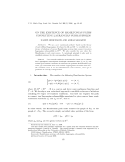
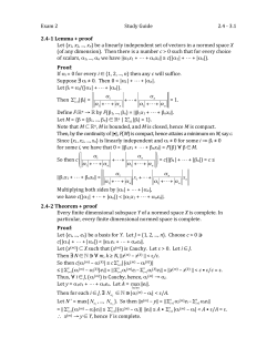
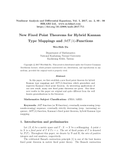
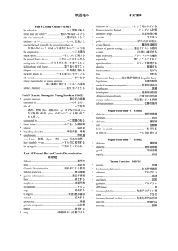
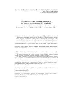
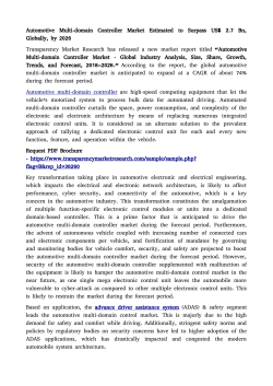
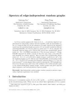
© Copyright 2026 Paperzz