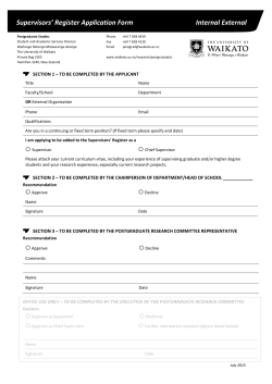
Supervisor Engine 32 Memory Installation Note
Product Numbers: MEM-XCEF720-512M=, MEM-XCEF720-1GB=
This publication describes how to replace the dynamic random-access memory (DRAM) dual inline
memory module (DIMM) on the Supervisor Engine 32.
Note
Any Supervisor Engine 32 that was shipped after May 2006 has 512 MB of DRAM as the default
memory configuration.
Contents
This publication consists of these sections:
Note
•
Safety Overview, page 2
•
Installing the DRAM Memory Kit, page 6
•
Translated Safety Warnings, page 22
•
Obtaining Documentation and Submitting a Service Request, page 30
For translations of the warnings in this publication, see the “Translated Safety Warnings” section on
page 22.
Corporate Headquarters:
Cisco Systems, Inc., 170 West Tasman Drive, San Jose, CA 95134-1706 USA
© 2005–2006 Cisco Systems, Inc. All rights reserved.
Safety Overview
Safety Overview
Safety warnings appear throughout this publication in procedures that may harm you if performed
incorrectly. A warning symbol precedes each warning statement.
Statement 1071—Warning Definition
Warning
IMPORTANT SAFETY INSTRUCTIONS
This warning symbol means danger. You are in a situation that could cause bodily injury. Before you
work on any equipment, be aware of the hazards involved with electrical circuitry and be familiar
with standard practices for preventing accidents. To see translations of the warnings that appear in
this publication, refer to the translated safety warnings that accompanied this device.
Note: SAVE THESE INSTRUCTIONS
Note: This documentation is to be used in conjunction with the specific product installation guide
that shipped with the product. Please refer to the Installation Guide, Configuration Guide, or other
enclosed additional documentation for further details.
Waarschuwing
BELANGRIJKE VEILIGHEIDSINSTRUCTIES
Dit waarschuwingssymbool betekent gevaar. U verkeert in een situatie die lichamelijk letsel kan
veroorzaken. Voordat u aan enige apparatuur gaat werken, dient u zich bewust te zijn van de bij
elektrische schakelingen betrokken risico's en dient u op de hoogte te zijn van de standaard
praktijken om ongelukken te voorkomen. Voor een vertaling van de waarschuwingen die in deze
publicatie verschijnen, dient u de vertaalde veiligheidswaarschuwingen te raadplegen die bij dit
apparaat worden geleverd.
Opmerking BEWAAR DEZE INSTRUCTIES.
Opmerking Deze documentatie dient gebruikt te worden in combinatie met de
installatiehandleiding voor het specifieke product die bij het product wordt geleverd. Raadpleeg de
installatiehandleiding, configuratiehandleiding of andere verdere ingesloten documentatie voor
meer informatie.
Varoitus
TÄRKEITÄ TURVALLISUUTEEN LIITTYVIÄ OHJEITA
Tämä varoitusmerkki merkitsee vaaraa. Olet tilanteessa, joka voi johtaa ruumiinvammaan. Ennen
kuin työskentelet minkään laitteiston parissa, ota selvää sähkökytkentöihin liittyvistä vaaroista ja
tavanomaisista onnettomuuksien ehkäisykeinoista. Tässä asiakirjassa esitettyjen varoitusten
käännökset löydät laitteen mukana toimitetuista ohjeista.
Huomautus SÄILYTÄ NÄMÄ OHJEET
Huomautus Tämä asiakirja on tarkoitettu käytettäväksi yhdessä tuotteen mukana tulleen
asennusoppaan kanssa. Katso lisätietoja asennusoppaasta, kokoonpano-oppaasta ja muista
mukana toimitetuista asiakirjoista.
Supervisor Engine 32 Memory Installation Note
2
78-16999-02
Safety Overview
Attention
IMPORTANTES INFORMATIONS DE SÉCURITÉ
Ce symbole d'avertissement indique un danger. Vous vous trouvez dans une situation pouvant causer
des blessures ou des dommages corporels. Avant de travailler sur un équipement, soyez conscient
des dangers posés par les circuits électriques et familiarisez-vous avec les procédures couramment
utilisées pour éviter les accidents. Pour prendre connaissance des traductions d'avertissements
figurant dans cette publication, consultez les consignes de sécurité traduites qui accompagnent cet
appareil.
Remarque CONSERVEZ CES INFORMATIONS
Remarque Cette documentation doit être utilisée avec le guide spécifique d'installation du produit
qui accompagne ce dernier. Veuillez vous reporter au Guide d'installation, au Guide de
configuration, ou à toute autre documentation jointe pour de plus amples renseignements.
Warnung
WICHTIGE SICHERHEITSANWEISUNGEN
Dieses Warnsymbol bedeutet Gefahr. Sie befinden sich in einer Situation, die zu einer
Körperverletzung führen könnte. Bevor Sie mit der Arbeit an irgendeinem Gerät beginnen, seien Sie
sich der mit elektrischen Stromkreisen verbundenen Gefahren und der Standardpraktiken zur
Vermeidung von Unfällen bewusst. Übersetzungen der in dieser Veröffentlichung enthaltenen
Warnhinweise sind im Lieferumfang des Geräts enthalten.
Hinweis BEWAHREN SIE DIESE SICHERHEITSANWEISUNGEN AUF
Hinweis Dieses Handbuch ist zum Gebrauch in Verbindung mit dem Installationshandbuch für Ihr
Gerät bestimmt, das dem Gerät beiliegt. Entnehmen Sie bitte alle weiteren Informationen dem
Handbuch (Installations- oder Konfigurationshandbuch o. Ä.) für Ihr spezifisches Gerät.
Figyelem!
FONTOS BIZTONSÁGI ELÕÍRÁSOK
Ez a figyelmezetõ jel veszélyre utal. Sérülésveszélyt rejtõ helyzetben van. Mielõtt bármely
berendezésen munkát végezte, legyen figyelemmel az elektromos áramkörök okozta kockázatokra,
és ismerkedjen meg a szokásos balesetvédelmi eljárásokkal. A kiadványban szereplõ
figyelmeztetések fordítása a készülékhez mellékelt biztonsági figyelmeztetések között található.
Megjegyzés ÕRIZZE MEG EZEKET AZ UTASÍTÁSOKAT!
Megjegyzés Ezt a dokumentációt a készülékhez mellékelt üzembe helyezési útmutatóval együtt kell
használni. További tudnivalók a mellékelt Üzembe helyezési útmutatóban (Installation Guide),
Konfigurációs útmutatóban (Configuration Guide) vagy más dokumentumban találhatók.
Avvertenza
IMPORTANTI ISTRUZIONI SULLA SICUREZZA
Questo simbolo di avvertenza indica un pericolo. La situazione potrebbe causare infortuni alle
persone. Prima di intervenire su qualsiasi apparecchiatura, occorre essere al corrente dei pericoli
relativi ai circuiti elettrici e conoscere le procedure standard per la prevenzione di incidenti. Per le
traduzioni delle avvertenze riportate in questo documento, vedere le avvertenze di sicurezza che
accompagnano questo dispositivo.
Nota CONSERVARE QUESTE ISTRUZIONI
Nota La presente documentazione va usata congiuntamente alla guida di installazione specifica
spedita con il prodotto. Per maggiori informazioni, consultare la Guida all'installazione, la Guida
alla configurazione o altra documentazione acclusa.
Supervisor Engine 32 Memory Installation Note
78-16999-02
3
Safety Overview
Advarsel
VIKTIGE SIKKERHETSINSTRUKSJONER
Dette varselssymbolet betyr fare. Du befinner deg i en situasjon som kan forårsake personskade.
Før du utfører arbeid med utstyret, bør du være oppmerksom på farene som er forbundet med
elektriske kretssystemer, og du bør være kjent med vanlig praksis for å unngå ulykker. For å se
oversettelser av advarslene i denne publikasjonen, se de oversatte sikkerhetsvarslene som følger
med denne enheten.
Merk TA VARE PÅ DISSE INSTRUKSJONENE
Merk Denne dokumentasjonen skal brukes i forbindelse med den spesifikke
installasjonsveiledningen som fulgte med produktet. Vennligst se installasjonsveiledningen,
konfigureringsveiledningen eller annen vedlagt tilleggsdokumentasjon for detaljer.
Aviso
INSTRUÇÕES IMPORTANTES DE SEGURANÇA
Este símbolo de aviso significa perigo. O utilizador encontra-se numa situação que poderá ser
causadora de lesões corporais. Antes de iniciar a utilização de qualquer equipamento, tenha em
atenção os perigos envolvidos no manuseamento de circuitos eléctricos e familiarize-se com as
práticas habituais de prevenção de acidentes. Para ver traduções dos avisos incluídos nesta
publicação, consulte os avisos de segurança traduzidos que acompanham este dispositivo.
Nota GUARDE ESTAS INSTRUÇÕES
Nota Esta documentação destina-se a ser utilizada em conjunto com o manual de instalação
incluído com o produto específico. Consulte o manual de instalação, o manual de configuração ou
outra documentação adicional inclusa, para obter mais informações.
¡Advertencia!
INSTRUCCIONES IMPORTANTES DE SEGURIDAD
Este símbolo de aviso indica peligro. Existe riesgo para su integridad física. Antes de manipular
cualquier equipo, considere los riesgos de la corriente eléctrica y familiarícese con los
procedimientos estándar de prevención de accidentes. Vea las traducciones de las advertencias
que acompañan a este dispositivo.
Nota GUARDE ESTAS INSTRUCCIONES
Nota Esta documentación está pensada para ser utilizada con la guía de instalación del producto
que lo acompaña. Si necesita más detalles, consulte la Guía de instalación, la Guía de
configuración o cualquier documentación adicional adjunta.
Varning!
VIKTIGA SÄKERHETSANVISNINGAR
Denna varningssignal signalerar fara. Du befinner dig i en situation som kan leda till personskada.
Innan du utför arbete på någon utrustning måste du vara medveten om farorna med elkretsar och
känna till vanliga förfaranden för att förebygga olyckor. Se översättningarna av de
varningsmeddelanden som finns i denna publikation, och se de översatta säkerhetsvarningarna som
medföljer denna anordning.
OBS! SPARA DESSA ANVISNINGAR
OBS! Denna dokumentation ska användas i samband med den specifika
produktinstallationshandbok som medföljde produkten. Se installationshandboken,
konfigurationshandboken eller annan bifogad ytterligare dokumentation för närmare detaljer.
Supervisor Engine 32 Memory Installation Note
4
78-16999-02
Safety Overview
Supervisor Engine 32 Memory Installation Note
78-16999-02
5
Installing the DRAM Memory Kit
Installing the DRAM Memory Kit
This section is divided into the following topics:
Warning
•
Required Tools, page 6
•
Removing the Supervisor Engine 32 from the Chassis, page 7
•
Removing and Installing the DRAM DIMMs, page 9
•
Installing the Supervisor Engine 32, page 13
Only trained and qualified personnel should be allowed to install, replace, or service this equipment.
Statement 1030
Required Tools
The following tools are required to perform the memory kit installation:
•
Antistatic mat or foam pad to support and protect the removed supervisor engine
•
3/16-inch flat-blade screwdriver for the captive installation screws on the supervisor engine
•
Your own ESD-prevention equipment or the disposable grounding wrist strap included with all
upgrade kits, field-replaceable units (FRUs), and spares
Caution
Always use an ESD wrist strap when handling modules or coming into contact with internal components.
Warning
Blank faceplates and cover panels serve three important functions: they prevent exposure to
hazardous voltages and currents inside the chassis; they contain electromagnetic interference (EMI)
that might disrupt other equipment; and they direct the flow of cooling air through the chassis. Do not
operate the system unless all cards, faceplates, front covers, and rear covers are in place.
Statement 1029
Warning
Hazardous voltage or energy is present on the backplane when the system is operating. Use caution
when servicing. Statement 1034
Supervisor Engine 32 Memory Installation Note
6
78-16999-02
Installing the DRAM Memory Kit
Removing the Supervisor Engine 32 from the Chassis
To install the DRAM memory kit, you must first remove the Supervisor Engine 32 from the chassis.
The Supervisor Engine 32 is a required system component. If only one Supervisor Engine 32 is present,
removing it while the system is operating causes the system to halt. When two Supervisor Engine 32s
are installed, hot swapping allows you to remove and replace one of the supervisor engines without
turning off the system power.
Warning
During this procedure, wear grounding wrist straps to avoid ESD damage to the card. Do not directly
touch the backplane with your hand or any metal tool, or you could shock yourself. Statement 94
To remove the Supervisor Engine 32, follow these steps:
Step 1
Attach an ESD grounding strap to your wrist and to ground. (If you are unsure about the correct way to
attach an ESD grounding strap, refer to the “Attaching Your ESD Grounding Strap” section on page 19
for instructions.)
Step 2
If there is only one SDisconnect any interface cables attached to the supervisor engine.
Step 3
Verify that the captive installation screws on all of the modules in the chassis are tight. This step ensures
that the space created by the removed supervisor engine is maintained.
Note
If the captive installation screws are loose, the EMI gaskets on the installed modules will push
the modules toward the open slot, reducing the opening size and making it difficult to reinstall
the supervisor engine.
Step 4
Loosen the two captive screws on the supervisor engine that is to be removed.
Step 5
Depending on the orientation of the slots in the chassis (horizontal or vertical), perform one of the
following two sets of steps:
Horizontal slots
a.
Place your thumbs on the left and right ejector levers, and simultaneously rotate the levers outward
to unseat the supervisor engine from the backplane connector. (See Figure 1.)
b.
Grasp the front edge of the supervisor engine, and slide the supervisor engine partially out of the
slot. Place your other hand under the supervisor engine to support the weight of the module. Do not
touch the module circuitry. (See Figure 2.)
Vertical slots
Step 6
a.
Place your thumbs on the ejector levers located at the top and bottom of the supervisor engine, and
simultaneously rotate the levers outward to unseat the supervisor engine from the backplane
connector.
b.
Grasp the edges of the supervisor engine, and slide the supervisor engine straight out of the slot. Do
not touch the module circuitry.
Immediately place the supervisor engine on an antistatic mat or antistatic foam.
Supervisor Engine 32 Memory Installation Note
78-16999-02
7
Installing the DRAM Memory Kit
Figure 1
Opening the Ejector Levers (Horizontal Chassis Shown)
1
2
WS-X6624-FXS
3
US
AT
ST
24 PORT FXS ANALOG
1
4
7
10
13
16
19
22
2
5
8
11
14
17
20
23
3
6
9
12
15
18
21
24
19
22
24
-1
STATION
WS-X6624-FXS
4
US
AT
ST
24 PORT FXS ANALOG
1
4
7
10
13
16
2
5
8
11
14
17
20
23
3
6
9
12
15
18
21
24
24
-1
STATION
5
1
WS-X6348-RJ-45V
2
12
14
24
26
6
36
38
48
2
3
4
5
6
7
8
9
10
11
12
48 PORT
10/100 BASE-T
13
14
15
16
17
18
19
20
21
22
23
24
ETHERNET SWITCHING
MODULE
25
26
27
28
29
30
31
32
33
34
35
36
37
38
39
40
41
42
43
44
45
46
47
48
130906
1
o
o
INPUT
OK
FAN
OK
OUTPUT
FAIL
INPUT
OK
Ejector lever
FAN
OK
OUTPUT
FAIL
Captive
installation
screw
Supervisor Engine 32 Memory Installation Note
8
78-16999-02
Installing the DRAM Memory Kit
Figure 2
Removing the Supervisor Engine from the Chassis (Horizontal Chassis Shown)
1
2
WS-X6624-FXS
3
US
AT
ST
24 PORT FXS ANALOG
1
4
7
10
13
16
19
22
2
5
8
11
14
17
20
23
3
6
9
12
15
18
21
24
19
22
24
-1
STATION
WS-X6624-FXS
4
US
AT
ST
24 PORT FXS ANALOG
1
4
7
10
13
16
2
5
8
11
14
17
20
23
3
6
9
12
15
18
21
24
24
-1
STATION
5
WS-X6348-RJ-45V
1
2
12
14
24
6
26
36
38
48
2
3
4
5
6
7
8
9
10
11
12
48 PORT
10/100 BASE-T
13
14
15
16
17
18
19
20
21
22
23
24
ETHERNET SWITCHING
MODULE
25
26
27
28
34
35
36
37
38
39
40
41
42
43
44
45
46
47
48
130907
1
o
o
INPUT
OK
FAN
OK
OUTPUT
FAIL
INPUT
OK
FAN
OK
OUTPUT
FAIL
Removing and Installing the DRAM DIMMs
This section covers the removal of the DRAM DIMM and the installation of the new DRAM DIMM.
To install the DRAM DIMM kit, perform these steps:
Step 1
Attach an ESD grounding strap to your wrist and to ground. (If you are unsure about the correct way to
attach an ESD grounding strap, refer to the “Attaching Your ESD Grounding Strap” section on page 19
for instructions.)
Step 2
Locate the DRAM DIMM on the supervisor engine. (See Figure 3.)
Supervisor Engine 32 Memory Installation Note
78-16999-02
9
Installing the DRAM Memory Kit
DRAM DIMM Location on the Supervisor Engine 32
DRAM DIMM
Step 3
130912
Figure 3
Release the old DRAM DIMM from its socket by simultaneously pulling the two locking spring tabs on
the socket sides outward and pivoting the DRAM DIMM free of the tabs. Be careful not to bend the
locking spring tabs too far, you can break the tabs on the DIMM socket. (See Figure 4.)
Supervisor Engine 32 Memory Installation Note
10
78-16999-02
Installing the DRAM Memory Kit
Figure 4
Releasing the Spring Clips
Pull the tabs away with
your thumbs, bracing your
forefingers against the
rails. The memory module
will be released. Then raise
the memory module to
a vertical position.
51543
Memory module
Step 4
Holding the DIMM by its edges, (see Figure 5), gently rock and lift it to disconnect it from the DIMM
socket. Immediately place the DRAM DIMM on an antistatic mat or in an antistatic bag.
Handling a DIMM
28580
Figure 5
Step 5
Remove the replacement DRAM DIMM from the antistatic package.
Step 6
Holding the DIMM between your thumbs and forefingers, with the connector edge (the metal fingers)
down, carefully slide the DIMM into the socket. Make sure that you fully insert the connector edge of
the DIMM into the socket connector.
Note
A notch (key) is located on the left connector edge of the DIMM. This notch key ensures that
the DIMM is correctly oriented in the socket.
Supervisor Engine 32 Memory Installation Note
78-16999-02
11
Installing the DRAM Memory Kit
Caution
Step 7
When inserting the DIMM, use firm but not excessive pressure. If you damage a socket, you will have
to return the supervisor engine to Cisco for repair.
Press down on the edges of the DIMM until the DIMM clicks into place (see Figure 6).
Installing the DIMM in the Socket
130913
Figure 6
Supervisor Engine 32 Memory Installation Note
12
78-16999-02
Installing the DRAM Memory Kit
Installing the Supervisor Engine 32
Warning
During this procedure, wear grounding wrist straps to avoid ESD damage to the card. Do not directly
touch the backplane with your hand or any metal tool, or you could shock yourself. Statement 94
To reinstall the Supervisor Engine 32 in the chassis, follow these steps:
Step 1
Attach an ESD grounding strap to your wrist and to ground. (If you are unsure about the correct way to
attach an ESD grounding strap, refer to the “Attaching Your ESD Grounding Strap” section on page 19
for instructions.)
Step 2
Verify that the captive installation screws are tightened on all supervisor engines installed in the chassis.
This action assures that the EMI gaskets on all supervisor engines are fully compressed in order to
maximize the opening space for the removed supervisor engine.
Note
Step 3
If the captive installation screws are loose, the EMI gaskets on the installed modules will push
adjacent modules toward the open slot, reducing the opening size and making it difficult to
install the removed supervisor engine.
Fully open both ejector levers on the supervisor engine being installed.
Supervisor Engine 32 Memory Installation Note
78-16999-02
13
Installing the DRAM Memory Kit
Step 4
Depending on the orientation of the slots in the chassis (horizontal or vertical), perform one of the
following two sets of steps:
Horizontal slots
a.
Position the supervisor engine in the slot. (See Figure 7.) Make sure that you align the sides of the
module carrier with the slot guides on each side of the slot.
b.
Carefully slide the supervisor engine into the slot until the EMI gasket along the top edge of the
module makes contact with the module in the slot above it and both ejector levers have closed to
approximately 45 degrees with respect to the module faceplate. (See Figure 8.)
c.
Using the thumb and forefinger of each hand, grasp the two ejector levers and press down to create
a small 0.040 inch (1 mm) gap between the supervisor engine’s EMI gasket and the module above
it. (See Figure 8.)
Note
d.
While pressing down, simultaneously close the left and right ejector levers to fully seat the
supervisor engine in the backplane connector. The ejector levers are fully closed when they are flush
with the module faceplate. (See Figure 8.)
Note
e.
Failure to fully seat the module in the backplane connector can result in error messages.
Tighten the two captive installation screws on the supervisor engine.
Note
f.
Do not press down too forcefully on the levers because they will bend and be damaged.
Make sure that the ejector levers are fully closed before tightening the captive installation
screws.
If the chassis is powered down, power-up the chassis.
Verify that the STATUS LED is lit. Periodically check the STATUS LED. If the STATUS LED
changes from orange to green, the supervisor engine has successfully completed the boot process
and is now online. If the STATUS LED remains orange or turns red, the supervisor engine has not
successfully completed the boot process and may have encountered an error.
Supervisor Engine 32 Memory Installation Note
14
78-16999-02
Installing the DRAM Memory Kit
Figure 7
Positioning the Module in a Horizontal Slot Chassis
Insert module
between slot guides
EMI gasket
3
4
5
6
4
5
6
1
2
3
4
FAN
STATUS 5
EMI gasket
130908
6
o
o
INPUT
OK
FAN
OK
OUTPUT
FAIL
INPUT
OK
FAN
OK
OUTPUT
FAIL
Ejector lever fully
extended
Supervisor Engine 32 Memory Installation Note
78-16999-02
15
Installing the DRAM Memory Kit
Figure 8
Clearing the EMI Gasket in a Horizontal Slot Chassis
1
2
3
Press down
4
Press down
1
2
FAN
STATUS 5
6
3
4
1mm
5
6
6
Gap between the module
EMI gasket and the
module above it
130909
4
Supervisor Engine 32 Memory Installation Note
16
78-16999-02
Installing the DRAM Memory Kit
Vertical slots
a.
Position the supervisor engine in the slot. (See Figure 9.) Make sure that you align the sides of the
module carrier with the slot guides on the top and bottom of the slot.
b.
Carefully slide the supervisor engine into the slot until the EMI gasket along the right edge of the
module makes contact with the module in the slot adjacent to it and both ejector levers have closed
to approximately 45 degrees with respect to the module faceplate. (See Figure 10.)
Figure 9
Positioning the Module in a Vertical Slot Chassis
Ejector lever fully
extended
FAN
STATUS
WS-X6224
24 PORT 100FX
ST
AT
US
AC
TIV
E
EMI
gasket
NE
XT
SE
LE
CT
EMI
gasket
o
o
INPUT
OK
FAN
OK
OUTPUT
FAIL
INPUT
OK
FAN
OK
OUTPUT
FAIL
6
Insert module
between slot guides
130910
3
4
Supervisor Engine 32 Memory Installation Note
78-16999-02
17
Installing the DRAM Memory Kit
Figure 10
Clearing the EMI Gasket in a Vertical Slot Chassis
Gap between the module
EMI gasket and the
module above it
1mm
FAN
STATUS
48
Press left
130911
Press left
o
o
INPUT
OK
FAN
OK
OUTPUT
FAIL
INPUT
OK
c.
OUTPUT
FAIL
Using the thumb and forefinger of each hand, grasp the two ejector levers and exert a slight pressure
to the left, deflecting it approximately 0.040 inches (1 mm) creating a small gap between the
supervisor engine’s EMI gasket and the module adjacent to it. (See Figure 10.)
Note
d.
FAN
OK
Do not exert too much pressure on the ejector levers because they will bend and be damaged.
While pressing down on the ejector levers, simultaneously close the levers to fully seat the
supervisor engine in the backplane connector. The ejector levers are fully closed when they are flush
with the supervisor engine faceplate.
Supervisor Engine 32 Memory Installation Note
18
78-16999-02
Attaching Your ESD Grounding Strap
e.
Tighten the two captive installation screws on the supervisor engine.
Note
Make sure that the ejector levers are fully closed before tightening the captive installation
screws.
f.
If the chassis is powered down, power-up the chassis.
g.
Verify that the STATUS LED is lit. Periodically check the STATUS LED. If the STATUS LED
changes from orange to green, the supervisor engine has successfully completed the boot process
and is now online. If the STATUS LED remains orange or turns red, the supervisor engine has not
successfully completed the boot process and may have encountered an error.
Attaching Your ESD Grounding Strap
Electrostatic discharge (ESD) damage, which can occur when modules or other FRUs are improperly
handled, results in intermittent or complete failures. Modules consist of printed circuit boards that are
fixed in metal carriers. Electromagnetic interference (EMI) shielding and connectors are integral
components of the carrier. Although the metal carrier helps to protect the board from ESD, always use
an ESD grounding strap when handling modules.
Follow these guidelines for preventing ESD damage:
•
Always use an ESD wrist strap and ensure that it makes maximum contact with bare skin. ESD
grounding straps are available with banana plugs, metal spring clips, or alligator clips. All
Catalyst 6500 series chassis and Cisco 7600 series routers are equipped with a banana plug
connector (identified by the ground symbol next to the connector) somewhere on the front panel. If
you have an older chassis equipped with a plastic banana plug connector, we recommend that you
use either the supplied ESD grounding wrist strap (with a metal clip) or an ESD grounding wrist
strap equipped with an alligator clip. If you have a newer chassis that has a bare metal hole as the
banana plug connector (also identified by the ground symbol next to the connector), we recommend
that you use a personal ESD grounding strap equipped with a banana plug.
•
If you choose to use the disposable ESD wrist strap supplied with most FRUs or an ESD wrist strap
equipped with an alligator clip, you must attach the system ground lug to the chassis in order to
provide a proper grounding point for the ESD wrist strap.
Note
•
This system ground is also referred to as the network equipment building system (NEBS)
ground.
If your chassis does not have the system ground attached, you must install the system ground lug.
Refer to the your chassis installation documentation for the procedure.
Note
You do not need to attach a supplemental system ground wire to the system ground lug; the
lug provides a direct path to the bare metal of the chassis
Supervisor Engine 32 Memory Installation Note
78-16999-02
19
Attaching Your ESD Grounding Strap
After you install the system ground lug, follow these steps to correctly attach the ESD wrist strap:
Step 1
Attach the ESD wrist strap to bare skin as follows:
a.
If you are using the ESD wrist strap supplied with the FRUs, open the wrist strap package and
unwrap the ESD wrist strap. Place the black conductive loop over your wrist and tighten the strap
so that it makes good contact with your bare skin.
b.
If you are using an ESD wrist strap equipped with an alligator clip, open the package and remove
the ESD wrist strap. Locate the end of the wrist strap that attaches to your body and secure it to your
bare skin.
Step 2
Grasp the spring or alligator clip on the ESD wrist strap and momentarily touch the clip to a bare metal
spot (unpainted surface) on the rack. We recommend that you touch the clip to an unpainted rack rail so
that any built-up static charge is then safely dissipated to the entire rack.
Step 3
Attach either the spring clip or the alligator clip to the ground lug screw as follows (See Figure 11):
a.
If you are using the ESD wrist strap that is supplied with the FRUs, squeeze the spring clip jaws
open, position the spring clip to one side of the system ground lug screw head, and slide the spring
clip over the lug screw head so that the spring clip jaws close behind the lug screw head.
Note
b.
The spring clip jaws do not open wide enough to fit directly over the head of the lug screw
or the lug barrel.
If you are using an ESD wrist strap that is equipped with an alligator clip, attach the alligator clip
directly over the head of the system ground lug screw or to the system ground lug barrel.
Supervisor Engine 32 Memory Installation Note
20
78-16999-02
Attaching Your ESD Grounding Strap
Figure 11
Attaching the ESD Wrist Strap Clip to the System Ground Lug Screw
Clip
ESD ground
strap
Grounding lug
Screw
Side view of
grounding lug
Slide clip
behind screw
Clip installed
behind screw
System ground
connector
WS-X6K-SUP2-2GE
T
M
LE
G
US
O
EM
M
T
AT
ST
NS
R
SE
ST
SY
CO
PW
RE
Switch
100%
CONSOLE
PORT
MODE
CONSOLE
SUPERVISOR2
Load
PORT 1
PCMCIA
PORT 2
EJECT
OSM-4OC12 POS-SI
NK
LI
1
ST
AT
3
AC
TIV
RX
4 PORT OC-12 POS
TX
TX
2
RE
4
SM IR
LIN
K
1
2 LIN
K
LIN
K
3
4 LIN
SE
NK
LI
E
US
AC
TIV
E
RX
TX
TX
RX
T
R
IE M
RR AR
CA AL
PO
RT
AC
TIV
E
RX
R
IE M
RR AR
CA AL
K
TX
TX
RX
1
PO
RT
AC
TIV
E
RX
2
TX
TX
RX
R
IE M
RR AR
CA AL
PO
RT
RX
3
R
IE M
R R AR
CA AL
PO
RT
4
RT
4
144607
1%
OSM-4OC12 POS-SI
1
3
A
ST
U
AT
IV
CT
RX
TX
TX
S
4 PORT OC-12 POS
E
2
RE
4
SM IR
LIN
K
1
2 LIN
K
LIN
K
3
4 LIN
K
SE
AC
TIV
R
IE M
RR AR
CA AL
RX
TX
TX
RX
T
E
PO
RT
1
T
AC
E
RX
TX
TX
RX
R
IE M
RR AR
CA AL
IV
PO
RT
2
AC
TIV
RX
TX
TX
RX
R
IE M
RR AR
CA A L
E
PO
RT
3
RX
R
IE M
RR AR
CA AL
PO
In addition, follow these guidelines when handling modules:
Caution
•
Handle carriers by available handles or edges only; avoid touching the printed circuit boards or
connectors.
•
Place a removed component board-side-up on an antistatic surface or in a static shielding container.
If you plan to return the component to the factory, immediately place it in a static shielding
container.
•
Never attempt to remove the printed circuit board from the metal carrier.
For safety, periodically check the resistance value of the antistatic strap. The measurement should be
between 1 and 10 megohm (Mohm).
Supervisor Engine 32 Memory Installation Note
78-16999-02
21
Translated Safety Warnings
Translated Safety Warnings
This section repeats in multiple languages the basic warnings that appear in this publication.
Statement 1030—Equipment Installation
Warning
Waarschuwing
Varoitus
Only trained and qualified personnel should be allowed to install, replace, or service
this equipment.
Deze apparatuur mag alleen worden geïnstalleerd, vervangen of hersteld door bevoegd
geschoold personeel.
Tämän laitteen saa asentaa, vaihtaa tai huoltaa ainoastaan koulutettu ja laitteen
tunteva henkilökunta.
Attention
Il est vivement recommandé de confier l'installation, le remplacement et la maintenance de ces
équipements à des personnels qualifiés et expérimentés.
Warnung
Das Installieren, Ersetzen oder Bedienen dieser Ausrüstung sollte nur geschultem, qualifiziertem
Personal gestattet werden.
Avvertenza
Advarsel
Aviso
¡Advertencia!
Varning!
Questo apparato può essere installato, sostituito o mantenuto unicamente da un personale
competente.
Bare opplært og kvalifisert personell skal foreta installasjoner, utskiftninger eller service på
dette utstyret.
Apenas pessoal treinado e qualificado deve ser autorizado a instalar, substituir ou fazer a revisão
deste equipamento.
Solamente el personal calificado debe instalar, reemplazar o utilizar este equipo.
Endast utbildad och kvalificerad personal bör få tillåtelse att installera, byta ut eller reparera
denna utrustning.
Supervisor Engine 32 Memory Installation Note
22
78-16999-02
Translated Safety Warnings
Aviso
Advarsel
Somente uma equipe treinada e qualificada tem permissão para instalar, substituir ou dar
manutenção a este equipamento.
Kun uddannede personer må installere, udskifte komponenter i eller servicere dette udstyr.
Supervisor Engine 32 Memory Installation Note
78-16999-02
23
Translated Safety Warnings
Statement 1029—Blank Faceplates and Cover Panels
Warning
Blank faceplates and cover panels serve three important functions: they prevent exposure to
hazardous voltages and currents inside the chassis; they contain electromagnetic interference
(EMI) that might disrupt other equipment; and they direct the flow of cooling air through the chassis.
Do not operate the system unless all cards, faceplates, front covers, and rear covers are in place.
Waarschuwing
Lege vlakplaten en afdekpanelen vervullen drie belangrijke functies: ze voorkomen blootstelling
aan gevaarlijke voltages en stroom binnenin het frame, ze bevatten elektromagnetische storing
(EMI) hetgeen andere apparaten kan verstoren en ze leiden de stroom van koellucht door het frame.
Het systeem niet bedienen tenzij alle kaarten, vlakplaten en afdekkingen aan de voor- en achterkant
zich op hun plaats bevinden.
Varoitus
Tyhjillä tasolaikoilla ja suojapaneeleilla on kolme tärkeää käyttötarkoitusta: Ne suojaavat
asennuspohjan sisäisille vaarallisille jännitteille ja sähkövirralle altistumiselta; ne pitävät
sisällään elektromagneettisen häiriön (EMI), joka voi häiritä muita laitteita; ja ne suuntaavat
tuuletusilman asennuspohjan läpi. Järjestelmää ei saa käyttää, elleivät kaikki tasolaikat, etukannet
ja takakannet ole kunnolla paikoillaan.
Attention
Ne jamais faire fonctionner le système sans que l’intégralité des cartes, des plaques métalliques et
des panneaux avant et arrière ne soient fixés à leur emplacement. Ceux-ci remplissent trois
fonctions essentielles : ils évitent tout risque de contact avec des tensions et des courants
dangereux à l’intérieur du châssis, ils évitent toute diffusion d’interférences électromagnétiques
qui pourraient perturber le fonctionnement des autres équipements, et ils canalisent le flux d’air de
refroidissement dans le châssis.
Warnung
Blanke Faceplates und Abdeckungen haben drei wichtigen Funktionen: (1) Sie schützen vor
gefährlichen Spannungen und Strom innerhalb des Chassis; (2) sie halten elektromagnetische
Interferenzen (EMI) zurück, die andere Geräte stören könnten; (3) sie lenken den kühlenden
Luftstrom durch das Chassis. Das System darf nur betrieben werden, wenn alle Karten, Faceplates,
Voder- und Rückabdeckungen an Ort und Stelle sind.
Avvertenza
Le piattaforme bianche e i panelli di protezione hanno tre funzioni importanti: Evitano l'esposizione
a voltaggi e correnti elettriche pericolose nello chassis, trattengono le interferenze
elettromagnetiche (EMI) che potrebbero scombussolare altri apparati e dirigono il flusso di aria per
il raffreddamento attraverso lo chassis. Non mettete in funzione il sistema se le schede, le
piattaforme, i panelli frontali e posteriori non sono in posizione.
Advarsel
Aviso
Blanke ytterplater og deksler sørger for tre viktige funksjoner: de forhindrer utsettelse for farlig
spenning og strøm inni kabinettet; de inneholder elektromagnetisk forstyrrelse (EMI) som kan
avbryte annet utstyr, og de dirigerer luftavkjølingsstrømmen gjennom kabinettet. Betjen ikke
systemet med mindre alle kort, ytterplater, frontdeksler og bakdeksler sitter på plass.
As faces furadas e os painéis de protecção desempenham três importantes funções: previnem
contra uma exposição perigosa a voltagens e correntes existentes no interior do chassis; previnem
contra interferência electromagnética (EMI) que poderá danificar outro equipamento; e canalizam
o fluxo do ar de refrigeração através do chassis. Não deverá operar o sistema sem que todas as
placas, faces, protecções anteriores e posteriores estejam nos seus lugares.
Supervisor Engine 32 Memory Installation Note
24
78-16999-02
Translated Safety Warnings
¡Advertencia!
Las placas frontales y los paneles de relleno cumplen tres funciones importantes: evitan la
exposición a niveles peligrosos de voltaje y corriente dentro del chasis; reducen la interferencia
electromagnética (EMI) que podría perturbar la operación de otros equipos y dirigen el flujo de aire
de enfriamiento a través del chasis. No haga funcionar el sistema a menos que todas las tarjetas,
placas frontales, cubiertas frontales y cubiertas traseras estén en su lugar.
Varning!
Tomma framplattor och skyddspaneler har tre viktiga funktioner: de förhindrar att personer utsätts
för farlig spänning och ström som finns inuti chassit; de innehåller elektromagnetisk interferens
(EMI) som kan störa annan utrustning; och de styr riktningen på kylluftsflödet genom chassit. Använd
inte systemet om inte alla kort, framplattor, fram- och bakskydd är på plats.
Aviso
Advarsel
Plaquetas vazias e painéis de proteção têm três funções importantes: impedem a exposição a
tensões e correntes elétricas perigosas dentro do chassi; apresentam interferência
eletromagnética (EMI) que pode danificar outros equipamentos: direcionam o fluxo do ar
refrigerado pelo chassi. Não opere o sistema a menos que todas as placas, plaquetas, tampas
frontais e tampas traseiras estejam em seu devido lugar.
Blanke frontplader og sidepaneler tjener tre vigtige formål: de forhinder udsættelse for farlig
spænding og strøm inde i chassiset, de isolerer elektromagnetisk interferens (EMI), der kan forstyre
andet udstyr, og de leder en strøm af kølig luft gennem chassiset. Betjen ikke systemet medmindre
alle kort, frontplader, sidepaneler og bagpaneler er på plads.
Supervisor Engine 32 Memory Installation Note
78-16999-02
25
Translated Safety Warnings
Supervisor Engine 32 Memory Installation Note
26
78-16999-02
Translated Safety Warnings
Statement 1034—Backplane Voltage
Warning
Waarschuwing
Varoitus
Hazardous voltage or energy is present on the backplane when the system is operating. Use caution
when servicing.
Er is gevaarlijke spanning of energie aanwezig op de achterplaat wanneer het systeem bediend
wordt. Wees voorzichtig bij het onderhoud.
Kun laite on toiminnassa, taustalevyyn muodostuu vaarallista jännitettä. Ole varovainen
huoltaessasi laitetta.
Attention
Lorsque le système est en fonctionnement, des tensions électriques circulent sur le fond de panier.
Prendre des précautions lors de la maintenance.
Warnung
Wenn das System in Betrieb ist, treten auf der Rückwandplatine gefährliche Spannungen oder
Energien auf. Vorsicht bei der Wartung.
Avvertenza
Advarsel
Aviso
¡Advertencia!
Varning!
Aviso
Quando il sistema è in funzione, il pannello posteriore è sotto tensione pericolosa. Prestare
attenzione quando si lavora sul sistema.
Farlig spenning er til stede på bakpanelet når systemet kjøres. Utvis forsiktighet under service.
Há presença de voltagem perigosa ou de energia na placa traseira quando o sistema está em
operação. Tenha cuidado ao fazer a manutenção.
Cuando el sistema está en funcionamiento, el voltaje del plano trasero es peligroso. Tenga cuidado
cuando lo revise.
Farlig spänning föreligger på bakplattan när systemet körs. Var försiktig vid service.
O sistema em funcionamento emite tensão ou energia elétrica perigosa no painel traseiro. Seja
cauteloso ao fazer a manutenção.
Supervisor Engine 32 Memory Installation Note
78-16999-02
27
Translated Safety Warnings
Advarsel
Der er farlig spænding og energi på bagpladen når systemet er i brug. Vær forsigtig under
servicering.
Statement 94—Wrist Strap Warning
Warning
During this procedure, wear grounding wrist straps to avoid ESD damage to the card. Do not directly
touch the backplane with your hand or any metal tool, or you could shock yourself.
Waarschuwing
Draag tijdens deze procedure aardingspolsbanden om te vermijden dat de kaart beschadigd wordt
door elektrostatische ontlading. Raak het achterbord niet rechtstreeks aan met uw hand of met een
metalen werktuig, omdat u anders een elektrische schok zou kunnen oplopen.
Varoitus
Käytä tämän toimenpiteen aikana maadoitettuja rannesuojia estääksesi kortin vaurioitumisen
sähköstaattisen purkauksen vuoksi. Älä kosketa taustalevyä suoraan kädelläsi tai metallisella
työkalulla sähköiskuvaaran takia.
Supervisor Engine 32 Memory Installation Note
28
78-16999-02
Translated Safety Warnings
Attention
Lors de cette procédure, toujours porter des bracelets antistatiques pour éviter que des décharges
électriques n’endommagent la carte. Pour éviter l’électrocution, ne pas toucher le fond de panier
directement avec la main ni avec un outil métallique.
Warnung
Zur Vermeidung einer Beschädigung der Karte durch elektrostatische Entladung während dieses
Verfahrens ein Erdungsband am Handgelenk tragen. Bei Berührung der Rückwand mit der Hand oder
einem metallenen Werkzeug besteht Elektroschockgefahr.
Avvertenza
Durante questa procedura, indossare bracciali antistatici per evitare danni alla scheda causati da
un’eventuale scarica elettrostatica. Non toccare direttamente il pannello delle connessioni, né con
le mani né con un qualsiasi utensile metallico, perché esiste il pericolo di folgorazione.
Advarsel
Bruk jordingsarmbånd under prosedyren for å unngå ESD-skader på kortet. Unngå direkte berøring
av bakplanet med hånden eller metallverktøy, slik at di ikke får elektrisk støt.
Aviso
Durante este procedimento e para evitar danos ESD causados à placa, use fitas de ligação à terra
para os pulsos. Para evitar o risco de choque eléctrico, não toque directamente na parte posterior
com a mão ou com qualquer ferramenta metálica.
¡Advertencia!
Usartiras conectadas a tierra en las muñecas durante este procedimiento para evitar daños en la
tarjeta causados por descargas electrostáticas. No tocar el plano posterior con las manos ni con
ninguna herramienta metálica, ya que podría producir un choque eléctrico.
Varning!
Använd jordade armbandsremmar under denna procedur för att förhindra elektrostatisk skada på
kortet. Rör inte vid baksidan med handen eller metallverktyg då detta kan orsaka elektrisk stöt.
Supervisor Engine 32 Memory Installation Note
78-16999-02
29
Obtaining Documentation and Submitting a Service Request
Obtaining Documentation and Submitting a Service Request
For information on obtaining documentation, submitting a service request, and gathering additional
information, see the monthly What’s New in Cisco Product Documentation, which also lists all new and
revised Cisco technical documentation, at:
http://www.cisco.com/en/US/docs/general/whatsnew/whatsnew.html
Subscribe to the What’s New in Cisco Product Documentation as a Really Simple Syndication (RSS) feed
and set content to be delivered directly to your desktop using a reader application. The RSS feeds are a free
service and Cisco currently supports RSS Version 2.0.
This document is to be used in conjunction with the Catalyst 6500 Series Switch Module Guide.
CCSP, CCVP, the Cisco Square Bridge logo, Follow Me Browsing, and StackWise are trademarks of Cisco Systems, Inc.; Changing the Way We
Work, Live, Play, and Learn, and iQuick Study are service marks of Cisco Systems, Inc.; and Access Registrar, Aironet, BPX, Catalyst, CCDA,
CCDP, CCIE, CCIP, CCNA, CCNP, Cisco, the Cisco Certified Internetwork Expert logo, Cisco IOS, Cisco Press, Cisco Systems, Cisco Systems
Capital, the Cisco Systems logo, Cisco Unity, Enterprise/Solver, EtherChannel, EtherFast, EtherSwitch, Fast Step, FormShare, GigaDrive,
GigaStack, HomeLink, Internet Quotient, IOS, IP/TV, iQ Expertise, the iQ logo, iQ Net Readiness Scorecard, LightStream, Linksys, MeetingPlace,
MGX, the Networkers logo, Networking Academy, Network Registrar, Packet, PIX, Post-Routing, Pre-Routing, ProConnect, RateMUX,
ScriptShare, SlideCast, SMARTnet, The Fastest Way to Increase Your Internet Quotient, and TransPath are registered trademarks of Cisco Systems,
Inc. and/or its affiliates in the United States and certain other countries.
All other trademarks mentioned in this document or Website are the property of their respective owners. The use of the word partner does not imply
a partnership relationship between Cisco and any other company. (0601R)
© 2005–2006 Cisco Systems, Inc. All rights reserved.
Supervisor Engine 32 Memory Installation Note
30
78-16999-02
© Copyright 2026 Paperzz