1/7
AUGUST 2004
DS010005
THERMAL
ENERGY
METER
MC 108/ET
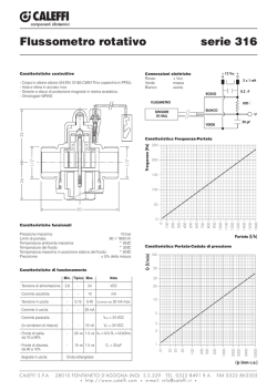
The temperature of thermal energy transported in a liquid vector traditionally needs a flow meter, two
temperature sensors and a calculation unit. Diagram 1 represents a simple diagram of the meter described in this
brochure. The EUROMAG INTERNATIONAL solution foresees the use of a flow meter with magnetic
induction coupled with an MC 108/ET converter plus two RTD. This system permits measurements, with a
single electronic, the thermal power and/or the thermal energy transported by the liquid beyond its range.
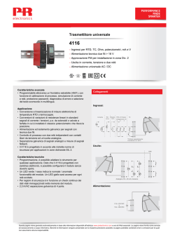
The MC108/ET converter is a special version of the MC108 converter normally
manufactured by EUROMAG INTERNATIONAL, from which it differs in
the added circuits of conditioning, the two RTD Pt 100 and the programme for
measuring the thermal energy (diagram 2). The MC108/ET converters can be
coupled with any “full board” sensor
manufactured by EUROMAG
INTERNATIONAL (table 1) according to the foreseen flow.
USCITE
CONTATORE
DI CALORE
CONVERTITORE
SENSORE
ELETTROMAGN.
LA VECCHIA SOLUZIONE
Diagram 1.
MC 108/ET
E
C
(KW)
4-20 mA potenza termica
EUROMAG
CONTATORE DI ENERGIA TERMICA
4-20 mA temperaturaA t
uscite:
PORTATA: SENSORE ELETTROMAGN.
4-20 mA potenza termica
TEMPERATURE: Pt 100
4-20 mA temperatura tA
impulsi (1 per KWh)
impulsi (1 per mc)
ALIMENTAZIONE......................................
TEMP. AMBIENTE: -20 °C ..... + 60 °C
n. matr........................................
GRADO DI PROTEZIONE : IP 67
energia termica (KWh)
volume (mc)
ALLARMI
RS 485
SENSORE
ELETTROMAGN.
Pt 100
Diagram 2.
2/7
AUGUST 2004
DS010005
1. CASE AND ASSEMBLY
The MC108/ET converters are cased in die-cast Aluminium with an IP 67 rate of protection. Access to the box
terminal board and the fuses is possible simply by removing the relative inspection cover on which all data is
indicated. On the front of the apparatus there is an LCD 2 line x 16 character display (eventually with back
lighting) and a 6 key keyboard provided with software key and, on request, a sealed cover. Also on request the
MC108 converter can be supplied blind, that is, without display and keyboard. Both the compact and separate
versions are available for assembly. In the compact version the MC108/ET converter can be installed in the
vertical position independent of the position of the sensor.
2. ON/OFF OUTPUT
The standard version of the MC108/ET converter has three ON/OFF outputs; the first is for the signal with a
frequency proportional to the range or the impulses of totalization, the second for programming alarms, the
third for hardware alarms. The first and second ON/OFF outputs permit the choice of connection of the load
to the collector or to the emitter so as to adapt the converter to any type of receiver (electromagnetic, electronic,
CMOS, TTL, etc.) and to any continuous external power supply inferior to 40 Vdc ( d 40 Vdc ) or to internal at
24 Vdc. Only the hardware alarm output is an open collector, in which case the load is connected between
converter and the positive clamp (+) of the output of the internal 24V. Protection is also foreseen for the output
in the case of: momentary over-voltage (zener intervention), inversion of polarity (ICC d 1A), short circuit for an
unlimited period in the case of internal supply. Should an external power supply be used for the ON/OFF
outputs, this MUST BE CONTINUOUS AND MUST NOT EXCEED 40 Vdc. Each output is able to pilot a
maximum power supply of 100mA. In the case of internal power supply of 24 Vdc, its MAXIMUM
RECEPTIVENESS IS 100 mA, and consequently the maximum supply deliverable from an output depends on
how many ON/OFF outputs are used contemporaneously; the additional modules must be taken into account.
3. OUTPUT 4(0) y 20 mA
This output permits the flow signal or the thermal power (client’s choice) to be transported to a distance of up
to 1 Km via a shielded two-wire cable, the maximum load permitted being 1000 Ohm. This output can also
supply information in conformity with the NAMUR NE 43 regulation regarding any possible faults in the meter
or malfunctions in the process. On request, a second output 4-20 mA for the transmission of the signal of a
temperature can be provided
4. INTERFACE RS485
This is an insulated interface found both on the terminal board and on the DIN socket. It permits the
connection of up to 32 flow meters on the network. In the case of blind measurers, without display, the interface
RS485 permits, via the DIN outlet, connection to the remote control TRM100, visualization of data and
predisposition of the necessary parameters for correct functioning of the measurers. The RS485 Interface
permits also connection to flow meters with the remote terminal TRM200 which can be installed at a distance of
1500 m. With this remote terminal the flow rate can be visualised at a distance and it is also possible to
programme at a distance.
5. DIGITAL INPUT
This input can be used in three different modes: to reset the counters, to stop them, or to choose the
measurement scale. There are two types of protection:
a) for momentary over-voltage (200 Vdc MAX per 1 ms, duty cycle 1%)
b) polarity inversion for unlimited time (Vin max =32 Vdc or 200 max V dc per 1 ms, duty cycle 1%)
6. INPUT FOR THERMAL RESISTENCE
Within the case of the MC108/ET converter a 4 wire module with two inputs for thermal resistance Pt100 for
measuring the temperature in the tubes both transmitting and receiving is installed.
3/7
AUGUST 2004
DS010005
7. REMOTE TRANSMISION OF MEASURMENTS
For remote transmission of measurements, two solutions, independent of the client’s requirements, are possible.
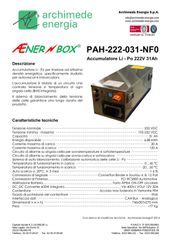
The first solution foresees a system similar to that shown in diagram 3. A TRM200 connected to the output
RS485, placed at a distance maximum of 1500 meters, permits both readings of the measurements available on
the MC108/ET converter and operation of all the presetting (full scale flow meter, temperature range,
measurement unites, etc.). It should also be remembered that numerous flow meters equipped with as many
MC108/ET can be connected in a single network capable of transmitting all measurements to a central unit
(TRM 200, PC, PLC, etc.)
MC 108/ET
anche in
esecuzione
compatta
EUROMAG
CONTATORE DI ENERGIA TERMICA
PORTATA: SENSORE ELETTROMAGN.
TEMPERATURE: Pt 100
ALIMENTAZIONE......................................
TEMP. AMBIENTE: -20 °C ..... + 60 °C
GRADO DI PROTEZIONE : IP 67
uscite:
4-20 mA potenza termica
4-20 mA temperatura tA
impulsi (1 per KWh)
impulsi (1 per mc)
n. matr........................................
TRM 200
distanza massima 1500 metri
EUROMAG
- ITALY
E
C
predisposizioni
indicazioni
uscite
SENSORE
ELETTROMAGN.
Pt 100
Diagram 3.
The second solution foresees only visualisation at a maximum distance of 1500 meters of the impulses emitted
by the converter MC108/ET via the use of an electronic impulse counter connected to the impulse output as
shown in diagram 4.
Diagram 4.
4/7
AUGUST 2004
DS010005
8. FUNCTIONS
The density of the water is given by equation supposing that the water is in such temperature and pressure
conditions that it will never reach saturation point (steam development). The apparatus integrates with respect to
time the thermal power and supplies an impulse every kWh (or its sub multiple). On the display it is possible to
visualise (in unit S.I. or techniques chosen by the client):
(1) water flow rate
(2) water volume
(3) inlet temperature
(4) outlet temperature
(5) thermal power
(6) thermal energy
(7) date and time
The totalized values (energy and volume) as well as the date and time are memorized, even in case of an
interruption of the mains power supply.
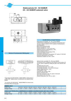
9. THERMO RESISTANCE
The temperature of the inlet and the outlet are established via
the RTD Pt 100 DIN 43760, selected in couples (max. error r
0,1 °C to 0°C). These RTD have 4 wires so that during
measurement the influence of the cable length is completely
eliminated. There are two standard models:
1) Model TRM-B-30-100, complete with a sump in AISI 316, of
5 mm diameter and 50 mm long under the connection. The
fitting of the sensor pocket to the process is a 1/4" gas
threaded joint. The RTD is also equipped with an IP 67
connector at 90° and 10 metres of 4 wire cable.
2) Model TRC-B-30-100 for insertion directly in the process by
means of a 1/8" threaded attachment gas UNI 338 and a
connector at 90°. Sensitive element in AISI 316 of 3 mm
diameter and length 24 mm. The thermal element is equipped
with a 4 contacts IP 67 connector.
Diagram 5.
10. CALIBRATION
Calibration of the instrument comprises calibration of the flow rate and of the two RTD’s.
For the first, a hydraulic bench equipped with an SIT certified balance can be used. The water measured by the
magnetic flow meter ("measured volume") is weighed on the scales; from this weight the "true volume" can be
obtained using the density value of test temperature. By means of digital operations on the instrument gain, one
can make the measured volume coincide with the true volume. To calibrate the temperature measurement
section, one can use sample resistances with values equal to those assumed by the PT 100 at the minimum and
maximum temperatures of the operating range of the instrument. These values are supplied by DIN 43760
Standard tables. The values of the sample resistances are controlled by a HP 34401 A multi-meter. While
awaiting to perform accurate tests in specialized laboratories, one can expect a global error of the thermal power
in the order of 1.5% of the full scale working with an 't of 20°C and a water velocity of 2-3m/s.
5/7
AUGUST 2004
DS010005
11. REFERENCE STANDARDS
The apparatus is manufactured according to the following standards:
CEI 66-5 (EN 61010/1)
EN 50081-1 (electromagnetic compatibility - emission)
EN 50082-1 (electromagnetic compatibility - immunity)
IEC 801-2
IEC 801-4
EN 55011
CEI ENV 50140
EN 61000-4-11
ISO 6817
ISO 11631
NAMUR NE 43
The apparatus is made according to EC regulations.
12. NOTES ON MEASUREMENTS
The equivalence between the principal measurements of thermal power and energy can be seen in Tables 2 and
3. Concerning this, the International System of units in force in Italy as of 1 January 1979 (Law of 14 April 1978
n. 122) foresees the use of watt and watt-hour and their multiples for thermal power and energy; the use of
calories and their multiples is no more in force.
MUT500
CP
SP
[2]
[1]
MC108/ET
x
x
[1] SP: SEPARATE
[2] CP: COMPACT
Table 1.
MUT501
CP
SP
[2]
[1]
x
x
W
1W
1
1 kW
103
1 MW
106
1 Btu/h
0,293
1 kcal/h
1,163
Table 2 – Thermal Power
COUPLING SENSORS
MUT1000
MUT1100
MUT2200
CP
SP
CP
SP
CP
SP
[2]
[1]
[2]
[1]
[2]
[1]
x
x
x
x
x
x
kW
10-3
1
103
MW
10-6
10-3
1
0,293 10-3
1,163 10-3
0,293 10-6
1,163 10-6
MUT2400
CP
SP
[2]
[1]
x
x
MUT2500
CP
SP
[2]
[1]
x
x
Btu/h
3,413
kcal/h
0,8598
3,413 103
3,413 106
1
3,968
0,8598 103
0,8598 106
0,2519
1
6/7
AUGUST 2004
DS010005
Wh
1
103
106
1 Wh
1 kWh
1 MWh
1J
0,278 10-3
1 Btu
0,293
1 kcal
1,163
Table 3 – Thermal Energy
kWh
10-3
1
103
MWh
10-6
10-3
1
0,278 10-6
0,293 10-3
1,163 10-3
0,278 10-9
0,293 10-6
1,163 10-6
J
3,6 103
3,6 106
3,6 109
1
1,0545 103
4,187 103
Btu
3,413
kcal
0,8598
3,413 103
3,413 106
0,948 10-3
1
3,968
0,8598 103
0,8598 106
0,239 10-3
0,2519
1
GENERAL CHARACTERISTICS
CHARACTERISTICS AND PERFORMANCE
MC108 HV
[1]
MC108 LV
[2]
x
x
x
[4]
x
x
x
x
x
x
x
x
x
x
x
x
x
x
x
x
x
x
x
x
[4]
x
x
x
x
x
x
x
x
x
x
x
x
x
x
x
x
x
Display with 2 lines of 16 characters
Keyboard
Output power supply 4(0) - 20 mA [3]
Second output power supply 4(0) - 20 mA [3][4]
Output Imp./ freq. 24 Vdc for impulses thermal energy [5]
Second output on/off 24 Vdc impulses water flow [5]
Third output on/off 24 Vdc (hardware alarms) [5]
Interface RS 485
Entrance for TRM 100
Network connection (RS 485)
Entrance Reset totalizers
Entrance for two RTD Pt 100 with 4 wires
Velocity of communication: 1200 y 2400 y 9600 y 19200 baud
Auto-ranging
Metric system: Decimal, English, American
Message languages: Italian or English
Power: 3y10 W [5]
Installation: Separate or Compact [6].
Degree of protection IP67
Working environmental temperature -20 °C a + 60 °C
Weight converter: 4000 g
[1] Electric power supply (high tension): 90y264 Vac, 45y66 Hz.
[2] Electric power supply (low tension): 16y28 Vac, 45y66 Hz, 19y33 Vdc.
[3] Maximum load 1000 Ohm.
This second output is optional on request
[5] Overall delivery of the two outputs ON/OFF max 100 mA
[6] Depends on the diameter of the sensor.
[7] The maximum length of the cable is 10 m.
Table 4.
7/7
AUGUST 2004
DS010005
OVERALL DIMENSIONS
MC108/ET
[1] Diagram 6
Table 5.
Dimensions and weight of MC308
Length
Height
176.0 mm
275.0 mm
Depth
132.0 mm
Weight
4000 g
265
275
C
2 FORI 0 6
E
275
218
176
136
2 FORI 0 6
132
Diagram 6.
The data shown in this manual are subject to modification without prior notice.
© Copyright 2026 Paperzz