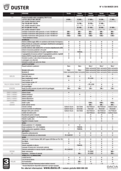
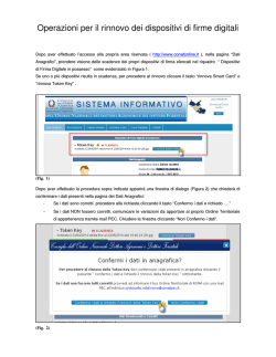
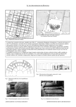
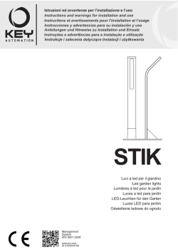
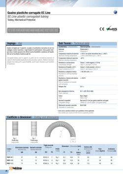
Mem. S.A.It. Suppl. Vol. 16, 14
c SAIt 2011
Memorie della
Supplementi
DUSTER (Dust in the Upper Stratosphere
Tracking Experiment and Return):
a balloon-borne dust particle collector
V. Della Corte1 , P. Palumbo1 , S. De Angelis1,2 , A. Ciucci1,2 , R. Brunetto1,3 , A. Rotundi1 ,
F.J.M. Rietmeijer4 , E. Zona1 , E. Bussoletti1 , L. Colangeli5 , F. Esposito6 ,
E. Mazzotta Epifani6 , V. Mennella6 , S. Peterzen7 , S. Masi8 , and R. Ibba9
1
2
3
4
5
6
7
8
9
Dip Scienze Applicate, Università di Napoli ’Parthenope’, Centro Direzionale 80143
Napoli, Italy. e-mail: [email protected]
Dipartimento Ingegneria Aerospaziale, Università di Napoli Federico II 80143 Napoli,
Italy.
European Space Astronomy Centre, 28691 Villanueva de la Cañada, Madrid, Spain
Department of Earth and Planetary Sciences, University of New Mexico, Albuquerque,
NM 87131-1116, USA
Solar System Division, Research and Scientific Support Department, European Space
Agency, ESTEC, Keplerlaan 1, PO Box 299, 2200 AG Noordwijk ZH, The Netherlands
INAF - Osservatorio Astronomico di Capodimonte 80131 Napoli, Italy
ISTAR (International Science Technology And Research) Pagosa Springs, Colorado USA
Dipartimento di Fisica, Università La Sapienza, 00100 Roma, Italy
ASI (Agenzia Spaziale Italiana),
The DUSTER (Dust in the Upper Stratosphere Tracking Experiment and
Retrieval) project is aimed at uncontaminated collection and retrieval of stratospheric solid
aerosol particles, in the submicron/micron range, from the upper stratosphere. The approach
implies: (1) in-situ particles collection; (2) sample recovering; and (3) laboratory analyses.
The scientific aim is deriving the dust size distribution, the concentration, chemistry and
mineralogy of the collected stratospheric aerosols. The main characteristics of the instrument are: (1) Capability of working autonomously during balloon flight at 30 − 40 km
altitude, temperatures down to −80◦C; (2) sampling at least 20 m3 of air to collect several
hundreds of aerosol particles); (3) Samples storage and retrieval under controlled conditions. A detailed description of the experiment is reported here.
Abstract.
Key words. Interplanetary dust – Stratospheric aerosol collection - balloon-borne
1. Introduction
Send offprint requests to: V. Della Corte
Stratospheric aerosols of grains with irregular shapes, variable sizes and chemi-
Della Corte et al.: DUSTER:a balloon-borne dust particle collector
cal compositions strongly influence climate
(Lacis et al. 1992; Wang et al. 2004) because
of their role in atmospheric chemistry, e.g.
ozone partitioning, heterogeneous reactions
(McElroy et al. 1986; Solomon et al. 1996)
(He & Carmichael 1999), and in radiative
forcing (Saxena & Yu 1996). Aerosols can
also be used as a tracer of atmospheric dynamics.
The long-term satellite-borne atmospheric
experiments of the past two decades yielded
global scale data about stratospheric aerosols.
To provide a complete and reliable estimate
of the properties of stratospheric aerosols,
it is desirable to validate satellite data with
in-situ aerosol sampling and remote scattering (Berthet et al. 2002) (Ackerman et al.
1989; Okada et al. 1997) and spectral measurements of twilight sky brightness in visual band (Mateshvili & Rietmeijer 2002;
Mateshvili et al. 2005).
A sampling of the stratosphere will invariably include particles from different sources
with relative contributions that vary as a function of time, altitude, and possibly geographic
location. At any time the stratosphere contains
extraterrestrial dust, dust from natural terrestrial sources (volcanic dust, wind-blown dust,
biomass burning) and dust related to anthropogenic activities.
While the previous experiments collecting and characterizing stratospheric dust at
the same altitudes and comparable particle
size ranges as investigated by DUSTER,
(Palumbo et al. 2008; Testa et al. 1990;
Okada et al. 1997) involved several steps in
laboratory handling, DUSTER was specifically designed to minimize and control
spurious effects, such as contamination, by
reducing post-flight sample manipulation
during laboratory analyses. We anticipate
DUSTER that will allow provide the following
critical information on solid aerosols:
– relative abundances of dust from different
sources (biomass burning, anthropogenic
activities, e.g. coal fly ash, volcanic and extraterrestrial particles);
15
– the efficiency of stratosphere injection
from these sources, residence time and
stratosphere mixing;
– chemical and physical properties of individual aerosol components;
– solid aerosol interactions with solar radiation, chemical and physical stability and
the role of aerosol as catalyst of chemical
reactions, their influence on local stratospheric physical and chemical conditions,
and any effects on atmospheric chemistry
and the global terrestrial radiation budget.
2. Requirements
The DUSTER instrument was developed
following previous experiences on stratospheric dust loading (Testa et al. 1990;
Mateshvili & Rietmeijer 2002) and the main
technical and operational requirements of collecting and characterizing solid stratospheric
aerosols on a regular basis as will be discussed
below. While the volatile component is routinely investigated, the refractory component
remains poorly studied.
Sample collection altitude range: 30 − 40
km. We concentrate on a poorly known stratospheric region, as it is not accessible with frequently operated high-flying aircraft platforms.
Ground-based observations are affected by the
foreground with much higher signal from the
troposphere and the lower stratosphere. Spacebased techniques can be more effective, but
data interpretation is based on assumed physical and chemical properties of the aerosol.
The targeted collection altitudes, together with
the choice of direct and low velocity dustdeposition collection on analytical substrates,
will require a stratospheric balloon-borne platform.
The collection device will allow low-speed
non-destructive and non-contaminant collection by sampling a sufficient volume of air. We
estimated that a minimum sampled volume of
about 20 m3 will be needed to achieve the collection of several hundreds of aerosol particles even in low stratospheric load conditions.
The collection technique we have chosen is the
inertial collection. This is a well-established
technique for solid particle monitoring, which
16
Della Corte et al.: DUSTER:a balloon-borne dust particle collector
is based on the decoupling between the gas
flux and particle when proper acceleration is
induced in the flux.
Sampling will be repeated at different times
and locations. The relative abundance of the
different aerosol components does depend on
time of the year, altitude and location, as different sources of dust with a wide size range
will have different residence times. Multiple
sampling at different times and locations either
implies an expensive long-term program for
multiple dedicated flights, or a flexible strategy to reduce costs. In order to have doable
program a small, lightweight and autonomous
instrument is needed. The instrument has to
be used as a piggyback payload, included as
a part of synergic payload ensemble on large
gondola, or as autonomous experiment on light
balloons. The technical requirements listed in
Table1 were considered for the instrument design. The block diagram is reported in Fig.1.
Table 1. Technical requirements for DUSTER instrument
Mass
Power
Volume
Operative Altitude
Operative Temperature
Flow Rate
Particle size range
≤ 35 kg
≤ 30 W
≤ 0.05 m3
30..40 km
−50..80 ◦C
1 m3 /h
0.1..100 µm
3. Instrument design
The instrument structure consists of a box
(410 × 310 × 310) mm3 realized by aluminum
bars Bosh Rexroth (Fig.2) and two aluminum
plates inserted into the box. The plates act as
support for the collecting and control elements
of the instrument, the first plate fixed under the
box holds the electronics and the battery of the
instrument, the second plate is mounted above
the electronics and holds the collection chamber and the pumping system.
The aluminum box is covered with 5 teflon
panels to ensure a benign environment for the
sensors, electronics and mechanical devices of
Fig. 1. DUSTER blocks diagram: (1)Control Unit;
(2)IRIDIUM Transceiver; (3)INLET pipe exposed
to atmosphere; (4)Gate valve connecting INLET
to collecting chamber; (5)Butterfly valve between
collecting chamber and pumping system; (6)pressure gauge monitoring flow through the instrument; (7)Pumping System with 6 micro-pump carbon vane; (8)Collecting susbstrate; (9)contamination control substrate.
the instrument. All the components of the instruments are inside the box except for the inlet
pipe, which to allow the atmospheric sampling,
protrudes from the teflon cover (Fig.3).
The atmospheric sampling is performed by
means of 6 carbon vane volumetric micropumps mounted on a supporting duct connected to the collection chamber, with a flow
rate of 1 m3 /h. An electrovalve is connected to
each pump exhaust (Fig.4): if a pump fails it
can be excluded from the pumping system by
closing the corresponding electrovalve without
compromising the sampling. The pumping system is connected to the collection chamber by
a flexible steel fitting.
In order to satisfy the cleanliness requirements the collection chamber is realized following Ultra High Vacuum Standards. The
chamber is constructed from Ergal (7075 aluminium alloy): 4 parts are connected with ConFlat flanges and copper gaskets (Fig.5). In the
chamber 2 identical substrates are accommodated: one exposed directly to the gas flow
(sample collector) the other in a secondary
chamber orthogonal to the flow (blank) dedicated to monitoring the contamination. The
chamber is sealed by two UHV valves, a gate
Della Corte et al.: DUSTER:a balloon-borne dust particle collector
17
valve connected to the inlet pipe and a butterfly
valve connected to the pumping system.
The valves are driven by two stepper motors controlled by the main electronics. In
order to guarantee cleanliness, a single shot
valve protects the inlet pipe; when the instrument reach the operative altitude the valve autonomously opens.
Fig. 3. DUSTER Instrument without teflon cover:
inlet pipe protruding from the structure.
Fig. 2. DUSTER mechanics: (1)Instrument assembled; (2)External box; (3)Instrument plate
with collecting chamber and pumping system;
(4)Electronics Box; (5)Bottom plate.
3.1. Instrument Control (electronics and
software, sensors)
Instrument electronics.
The heart of the electronics control system is an Athena II Diamond Systems PC104
SBC (Single Board Computer). The SBC combines the low-power, highly integrated VIA
Mark CoreFusionT M processor with on-board
memory and data acquisition into a compact
form factor. The Athena II is a small, low-heatdissipation, and extremely rugged embedded
CPU that fits in tight spaces and survives harsh
environments.
The SBC has 4 16450-compatible RS-232
serial ports. The built-in PC/104 expansion bus
enables the SBC to work with standards I/O
pc104 boards to control electromechanical devices of the instrument. The SBC has a fan-less
operating temperature range of −40 ◦C to +85
◦
C. The data acquisition circuit on board the
Athena II SBC performs all the sensors readings.
In order to control the stepper motors connected to the gate valves, 2 pc-104 AIMMotion-104 boards has been connected to the
SBC. The AIM104-MOTION-1 is an 8-bit
PC/104 module providing single axis motor
control, using Hewlett Packard’s HCTL-1100
motion controller IC. To control the pumps
switch on/off a relay module pc-104 has been
connected to the SBC. The DiamondSystems
IR104-PBF High Density Optoisolated Input
+ Relay Output PC/104 Module, 20 optoisolated digital inputs and 20 relay outputs, has
18
Della Corte et al.: DUSTER:a balloon-borne dust particle collector
Fig. 5. Collecting Chamber parts exploded view.
Fig. 4. DUSTER Instrument plate: pumping system
mounted with pumps and electrovalves.
been used. We designed and produced 2 custom pc104 in order to:
– Manage the 6 electrovalves of the pumping
system;
– Condition thermal and power consumption
sensors.
Instrument Telemetry Hardware.
An IRIDIUM 9601 SBD (Short Burst
Data) Transceiver has been used to implement
a telecommand/telemetry (TC/TM) system allowing operations control from ground through
commanding and housekeeping data transmission. The 9601 SBD Transceiver is a low cost,
Iridium Satellite LLC manufactured product,
designed as an OEM module to be integrated
into applications that only use the Iridium SBD
service. The transceiver is connected by a serial port (RS232 interface) to the instrument
main electronic boards. The 9601 is the core
transceiver module required to communicate
via the iridium network. Applications can read-
ily drive the transceiver using an extended AT
Command Set. The Iridium SBD service provides:
– Mobile Originated (instrument) messages
up to 340 bytes;
– Low, uniform global latency (less than 1
minute)
– Mobile Terminated (experimenter) messages up to 270 bytes
– Global Coverage.
The on-board Software sends Mobile
Originated SBD (MO-SBD) data messages via the Iridium Transceiver: it loads
the data message into the Transceiver and
instructs it to send the data message. The
data message is transmitted across the Iridium
satellite network to the Iridium Gateway. Then
the data message is transferred via e-mail or
an IP Socket to experimenter host computer
system where it is stored in a database for
further data processing. Mobile Terminated
SBD (MT-SBD) messages are sent to the
Iridium Gateway via e-mail or IP Socket from
the experimenter host computer system. The
Iridium Gateway sends a ’Ring Alert’ to the
Della Corte et al.: DUSTER:a balloon-borne dust particle collector
Transceiver when a MT-SBD message has
been queued.
Instrument Sensors and Thermal control.
The atmospheric pressure sensor (but for
redundancy two sensors are used) is a critical
part of the electronic subsystem: it measures
the barometric altitude and triggers the sampling process. The sensors HPA by Honeywell
provide an absolute pressure range from 0 to
121 kPa with ±0.03% full scale accuracy, in
the operating temperature range ( −40to85 ◦C
).
These sensors are connected to the Athena
II SBC by 2 RS 232 serial ports. A micro
electro-mechanical systems (MEMS) pressure
gauge sensor is connected to the pumping systems, with sensitivity of 0.1 mbar, in order to
monitor the flow rate through the instrument.
The thermometers used are 12 LM135 integrated circuit sensors, with a breakdown voltage directly proportional to absolute temperature (+10 mV/K). When calibrated at 25 ◦C the
LM135 has typically less than 1 ◦C error over a
100 ◦C temperature range; unlike other sensors
the LM135 has a linear output.
The sensors were used in conjunction with
the LM134 component (3-terminal adjustable
current sources) using the circuit reported in
Fig.6. Heaters are mounted on the valves of
the collecting chamber and on the support of
the pumps: if the temperature drops below
a set value the software activates the heaters
to maintain the components within the operational temperature.
19
Instrument Software.
The on-board software allows the complete management of the instrument operations
(open-close valve, switch on/off pumping system, sensors data storing and TC/TM managing). The instrument can operate in two different modes:
– Autonomous Mode;
– Slave Mode.
In the Autonomous Mode all operations
to sample and collect stratospheric aerosol are
handled by the software following data from
instrument sensors (atmospheric pressure, temperature, battery status). At the instrument
switch-on it is in the Safe Status (valves of the
collecting chambers closed and pumping system switched off).
The software continuously monitors and
stores the sensor readings (pressure, temperature and other housekeeping parameters);
when the pressure reaches the operative value
it changes the instrument to the Sampling
Status: opens the valves and switches on the
pumping system. The software sends, at regular time interval, sensors readings and instrument status by Iridium Transceiver. The sampling activity is triggered by the pressure readings (i.e. the balloon altitude).
If during the mission a thermal contingency, registered by sensors, occurs on critical
components (main electronics) the instrument
switch to the Safe Status configuration protecting the collected sampling. In Slave Mode the
operation is handled by the experimenter using
Telecommands. The Instrument receives TC
by the Iridium Transceiver and either changes
the instrument status or executes operations.
The software sends, by Iridium Transceiver,
sensors readings and instruments status. When
a thermal contingency occurs the instrument is
forced into Safe Status, in order to preserve the
collected sample.
Power Supply.
Fig. 6. Temperature sensors circuit with LM134
current source.
The electrical power required to operate
the instrument (20 W) during the sampling
20
Della Corte et al.: DUSTER:a balloon-borne dust particle collector
phase, is guaranteed by the combination of a
rechargeable battery with capacity of 20 Ah
and four solar panels (27 W each). The four
panels, connected in parallel to the rechargeable battery, are mounted in such a configuration that at least one them is pointed towards
the sun.
4. The 2008 Flight
The first DUSTER scientific flight was held
in June 2008. The Instrument was launched
with a 30000 m3 balloon from Longyearbyen
(Svalbard islands, Norway) on 21 st of June and
was recovered after a flight of about 3 days on
the west coast of Greenland (Fig.7). During the
flight the instrument was in Sampling Status
for 36 hours operating in the Autonomous
Mode, and was able to properly handle a thermal contingency of the main electronics. The
thermal and pressure data collected and stored
on board are displayed in Fig.8 and Fig.9. After
retrieval of the instrument 26 particles collected in the stratosphere at 37 km altitude were
identified by field emission scanning electron
microscopy (Ciucci et al. 2011).
Fig. 8. Pressure and Temperature measured and
stored on board by the DUSTER Altimeter during
2008 flight.
Fig. 9. Temperature measured by thermal sensors
during the 2008 flight, after the thermal contingency
on the CPU the instrument autonomously switch to
Safe Mode.
Fig. 7. DUSTER 2008 flight trajectory from
Longyearbyen (Svalbard, Norway) to Thule (northwest of Greenland).
5. Conclusions
The DUSTER instrument was developed to
collect small aerosol solid particles (0.1 −
150 µm) in the upper stratosphere (about 37
km. It operated for 36 hours autonomously
in a flight from Svalbard to Greenland (June
2008) sampling about 36 m3 of atmosphere
. The telecommand/telemetry system allowed
the control of the instrument during the flight.
The software properly managed a thermal contingency occurred to the main electronics saving the collected samples. The mechanical
structure and the collecting chamber safely survived the release and landing phases.
Acknowledgements. The DUSTER project has been
funded by the Italian Space Agency under contract I/015/07/0, SubTask 3350. We thank ASI for
the support given during the operational flight performed within launching site verification activities.
Della Corte et al.: DUSTER:a balloon-borne dust particle collector
References
Ackerman et al., 1989 J. Geophys. Res., 94,
8399
Berthet G. et al., 2002, Applied Optics, 41,
7522
Ciucci, A. et al., 2011, Memorie della Società
Astronomica Italiana Supplementi, 16, 119
He S. and Carmichael G.R., 1999, J. Geophys.
Res., 104, 26307
Lacis A. et al., 1992, Geophys. Res. Lett., 19,
1607
Mateshvili N. and Rietmeijer F.J.M., 2002, J.
Volc. Geothermal Res., 120, 55
21
Mateshvili N. et al., 2005, J. Geophys. Res.,
110, 1
McElroy, M. B., et al., 1986 Nature, 321, 759
Okada K. et al., 1997, J. Meteorological Soc.
of Japan., 75, 753
Palumbo,
P.,
et
al.
2008,
Mem. Soc. Astron. Italiana, 79, 853
Saxena V. and Yu S., 1996, J. Geophys. Res.,
101, 9063
Solomon S. et al., 1996, J. Geophys. Res.,
101(D3), 6713
Testa J.P. et al., 1990, Earth and Planet. Sci.
Letters, 98, 287
Wang C., 2004, J. Geophys. Res., 109, 4084
© Copyright 2026 Paperzz