-m
30-200
60, 90 AND 125 SKID-STEER
LOADERS
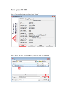
60 Skid-Steer Loader with utility bucket
CSM286
C'SM287
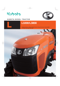
90 Skid-Steer Loader with light material bucket
CSM7Z4
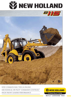
125 Sk/d-St8er Loader with dirt and foundry bucket and teeth
Aug. 64 litho in U.S.A.
~,
30-200-2
60,90
and 125 Skid-Steer
CI
Loaders
PRODUCT PROFILE
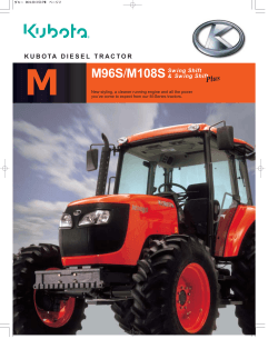
LARGE OPERATING CAPACITIES
Model 60-600 lb.
Model 90-700 lb.
Model 125 Gas-1325 lb.
Model 125 Diesel-141O lb.
Good productivity,
ROPS ROLL-GARD - STANDARD
Comes with canopy, side
screens and built-in lift
arm lock. - Operator
Safety.
'\
/
/
/
---
/
/
""",
- _/
,
.?""-
/:;.c:;
--
II
J I
\
~
\
\
\
'\
COMPACT DESIGN
Narrow width and short
overall length allows
working in tight areas.
'\
\
RUGGED ENGINES
Model 60 has 17-h.p.,
Model 90 has 23.0-h.p. and
Model 125 has 37-h.p. gas
or 40-h.p. diesel engines.
All engines have proven
themselves as reliable
power plants.
VARIETY OF BUCKETS
AND FORKS AVAILABLE
Handles many applications.
'OPERATIONAL AND
PARKING DISK BRAKES
CSM947
-
Providesafety and precise
control.
HYDROSTATIC DRIVES
Quick and responsive for
greater productivity.
Requires less maintenance
than belt-driven machines.
a
60, 90 and 125 Skid-Steer
30-200-3
Loaders
PRODUCT FEATURES
Compact and Maneuverable
John Deere skid-steer loaders are compact in design for
greater maneuverability in tight, close-quarter areas. They
will operate in areas in which the conventional, tractormounted loaders are too large to fit. Narrow and able to turn
within their own radiuses, these machines are fully at home
inside calf pens, milking barns and poultry houses. Other
applications include: general contractors, foundries, fertilizer plants, barge lines, nurseries and rental.
The little 60 Loader is only 35-1/4 inches wide; the 90 is 47
inches wide;and the Model 125is 59-1/2 inches wide. These
dimensions apply to those loaders equipped with standardequipment tires, and without buckets. For further information on size, see "Specifications".
Another reason that these machines will provide such outstanding maneuverability is their four-wheel drive features.
Left and right wheels operate independently of each other,
and can counter-rotate so that the loader can turn 360 degrees in its own track.
Engines
John Deere skid-steer loaders use engines that are designed for the rugged, tough use to which skid-steer loaders
are subjected.
125 Skid-Steer Loader
The 125is available with a liquid-cooled gasoline or diesel
engine. Both engines are compact and smooth in operation.
The 125 gasoline engine develops 37 horsepower at 2800
rpm. The continental engine has earned its reputation in
forklift trucks and other heavy-duty, industrial-type equipment. It provides a 21 percent torque rise.
The 125 Diesel engine develops 40 horsepower at 2800
rpm. The Isuzu Diesel has provided years of dependable
service for refrigeration units in semi-trailer trucks. John
Deere was the first to use Isuzu in a skid-steer loader. Today
it sets the standard for the industry.
Hydrostatic Drive
All three models utilize hydrostatic drive, for immediate
response and increased productivity. The hydrostatic system is totally independent of the hydraulic system. Hydrostatic drive also means less maintenance than for loaders
with variable drive systems. Hydrostatic drive eliminates
gear boxes, clutches, and variable drive belts, all high maintenance parts. This lower maintenance requirement will
help to increase productivity potential.
Hydrostatic
Drive Operation-60
and 90 Loaders
(60 Skid-Steer Loader shown)
The hydrostatic variable displacement, piston pumps are
mounted, side by side, under the loader seat. Drive pulleys
are located on the back of each pump behind the mounting
plate.
RIGHT
PUMP PULLEY
LEFT
,
P.UMP PULLEY
90 Skid-Steer Loader
The 90 uses a proven, two-cylinder, 23-horsepower, gasoline engine.This engine is well matched for the size of the 90
and is designed to giveexcellent reliability throughout years
of service.
60 Skid-Steer Loader
The engine used in the 60 is a two-cylinder, 17-horsepower, air-cooled, gasoline engine.
\
CSM948
ENGINE PULLEY
The two top pulleys are attached to the hydrostatic
pumps, and the lower pulley is attached to the engine crankshaft. A drive belt is routed around the pulleys. A belt idler,
activated by the drive clutch lever, takes up the slack in the
belt when the pumps are engaged.
(Continued on next page)
60, 90, and 125 Skid-Steer
30-200-4
D
Loaders
Hydrostatic Drive Operation60 and 90 Loaders-Continued
0
0
PUMP
FILTER
~
CSM949
(60 Skid-Steer Loader shown)
Each pump is connected by hose routing to a hydrostatic
gear motor. Hydraulic fluid is drawn by the pumps from the
reservoirthrough a filter. The pumps then deliver the pressurized fluid to the motors.
The motors and chains of the 60 Skid-Steer Loader are
located under the floor panel, in the 18-U.s.-gallon reservoir,
for cooling and lubrication.
REAR PRIVE SPROCKET
\
"'"
CSM950
FRONT DRIVE SPROCKET
(90 Skid-Steer Loader shown)
Sprockets on the output shaft of each motor are connected to each axle drive sprocket by a one-step drive chain, in
order-to obtain four-wheel drive.
(90 Skid-Steer Loader shown)
On the 90 Skid-Steer Loader, the ratio between engine
horsepower, hydrostatic motor size and reservoir size is such
that the motors have sufficient coolingwithout being placed
in the hydraulic reservoir.The chains are located in 1.5-U.S.gallon chain cases for lubrication ("A" above).
The 90 Loader features a T-bar, and the 60 Loader uses
two levers to control the direction and ground speed of the
loader. Two-lever control is necessary on the 60, in order to
allow easy entry and exit of its narrow operator station.
A neutral start safety switch is provided at the base of the
drive clutch lever. This means that the pumps must be disengaged before the engine will crank.
Aug. 84 Utho in U.S.A.
D
60, 90, and 125 Skid-Steer
Hydrostatic Drive Operation-125
Loader
,~~
MDUNTING
PLATE
(-'- -
/ВЈ1/
'\ ENGINE
FLYWHEEL
HOUSING
CSM951
&~
C7T\I---~~'
----"-:""
-- ---
--
I
_~I
--
I
-../;--~
'
y" ,:
, 'I . -;',
", ,;', :,' "
'" \"
--'I
,
c..:-::
\
II
,I
PUMP
(\
"'"
~
\\
-..-)
-
,~ z.'>"'-----~--
"'-'::-: ,<1-
, --:::::
"
\
\
I
\ ' \
\ \ \
\\\
~-,--""::::...~~ \ \
-- "; \ ~
II,' "I "' 2\
,. '.."~I,.?\'!
I, I__~__~ 'I" \ 1.---,..
"
..
\t
\\~---~
" .-~:- t-:/
\ " , --,
~-
\
/
1
-,.,'
CSM73'S
'
,
----,--" ,'r' -~
;:' .S'
-.. - ,
Engine power is transmitted to the hydrostatic, variabledisplacement-piston pumps. This is achieved by coupling
the rear hydrostatic pump input shaft with a splined hub
that is bolted to the engine flywheel.
-.;..-:'.:~---.(...., -\
',-",-..""- ..
--' ==-,-~,,=-,-~~,
.'" " - - - -,- - - ..:t~.
i~""-,
't, -~ -- 1_/
it}
'-- -
FLYWHEEL
SPLINED
HUB
30-200-5
Loaders
I
/~__~', t
'\' :'!
~\
\ '\
I'I:"'~'
I'/ 11,-""
I '/
1 II
I I
\
I,
\
\\
""
\
~
'~(
""'-",
I I , ,),\
',_~"":"r-:::::::" -~-::.-:.",...' -"'/'
..,.~'C~'- '",;:::"
. .,..
"
-
CSM952
-
-/..- \"---~'i
\,1 "
-' \ ,\~\ \~"'-
I
\
I,
I
\,,', "--"!"'~~' ,
"
-',
~
'I
~~
~
.~-'
~I/,
~
.-<
A sprocket on the output shaft of each motor is connected
to the axles by a two-step chain drive, in order to obtain fourwheel drive. Each side of the loader houses a 9-D.S.-gallon
hydraulic reservoir that also acts as a chain case to lubricate
the drive chains.
A neutral-start safety switch prevents the Model 125 from
being started while the T -bar control lever is activated.
Hydraulics
"I
\ \ \..\
\.
The front pump is coupled in tandem to the rear pump by
a splined input shaft. Each pump is connected by hoserouting to a fiXed-displacement-piston hydrostatic motor.
Hydraulic fluid is drawn by the pumps from the oil reservoir
through a filter. The pumps then deliver the fluid, under
pressure, to the motors through the dark colored hoses. One
hose is for forward motion and one is for rearward motion.
The hydraulic power for loader operation is supplied by a
15-gpm,gear-type pump on the 125and a 7.5-gpmpump on
the 60 and 90. The hydraulic system has a 1500-psi relief
setting on the 60; 1750-psion the 90;and 2000-psion the 125.
The standard spool valve directs oil flow to the lift and tilt
cylinders by actuating the foot pedals. The left pedal controls the up and down motion of the boom, with a heel-toe
movement; and the right pedal controls the bucket, in the
same fashion. The boom pedal (left) can be pushed down
with the toe and locked in a detent position, allowing the
boom to float with the contour of the ground when backdragging with the bucket. An auxiliary hydraulic valve kit
can be ordered as an attachment for field conversion. This
kit is standard on 125 (SNI20,OOI). This valve is
used to operate front-mounted attachments requiring hydraulic power.
Aug, 84 Litho in U,S,A,
30-200-6
60, 90, and 125 Skid-Steer
D
Loaders
lift Capacity
Although these machines are compact and able to work in
confined areas, they have large lift capacities. The operating
capacities are: 600 pounds for the 60 Loader; 700 pounds for
the 90 Loader; a big, 1325 pounds for the 125 Gas; and 1410
pounds for the 125 Diesel.
Operating Capacity, sometimes referred to as rated lift
capacity, is the safe load the loader can realistically handle
while operating. (SAE states it is not to exceed 50 percent of
the tipping load.)
It is important not to confuse operating capacity with
tipping load. Tipping Load is defined as the amount of
weight that causes the back wheels to come off the ground
under the following conditions:
(a)
(b)
(c)
(d)
(e)
loader at operating weight
loader on a hard level surface
loader stationary
maximum bucket rollback
center of gravity of the load is at the maximum forward position in the raising cycle. (see specifications
for specified height.)
Durability
Skid-steer loaders are commonly used hi abusive conditions and applications. For this reason, it is essential that
they be well built and durable. The John Deere skid-steer
loaders feature unitized main-frame construction. The
booms are of box construction, which gives maximum
strength with minimum weight.
A full length belly pan, standard on all units, provides
protection to the undercarriage.
Easy Servicing
(125 Skld-Steer Loader shown)
The operator's seat canbe removedin orderto exposethe
hydrostatic pumps and linkages on all units, and also the
hydrostatic motors on the 125.
(125 Skld-Steer
The cover for the hydraulic reservoir can be removed to
. provide accessto the drive chains on the 125;and to the drive
chains, drive motors and brakes on the 60 (as pictured on
page 25-1-4 showing the 60's motors and chains).
CSM295
(90 Skid-Steer
Loader shown)
Because of the compact size of skid-steer loaders, some
competitors do not provide easy access to their engines. This
is not the case with the John Deere skid-steer loaders. Routine engine maintenance can be performed easily at the rear
of the machine.
Aug. 84 Litho in U.S.A.
Loader shown)
(Continued on next page)
D
60, 90, and 125 Skid-Steer
30-200-7
PLASTIC FUEL LINERS
Easy Servicing-Continued
(90 Skid-Steer
Loaders
Loader shown)
The motors are under the floor panel on the Model 90.
The reservoir is located in the crossbeam between the boom
tower and in the boom towers. A convenient fill tube is
located on top of the crossbeam with a visible sight gauge
showing when the reservoir is full or when additional fluid is
needed. Access to the motors on the Model 90 is obtained by
pulling two clip pins to remove the seat, and removing four
capscrews to remove the one-piece T-barcowl and floor panel.
ENGINE SLIDE RAIL
(125 Loader Only)
(125 Skid-Steer Loader liner shown)
Removable plastic fuel tank liners are used on all three
models. This liner became standard equipment on 60 and
125 (SNI20,OOI) and 90 (SNI55,OOI). Plastic liners eliminate rust due to condensation. Also, if a foreign substance gets into the tank, cleaning and flushing is
easier.
Safety
A Roll-Gard~ ROPS with seat belt, canopy and side
screens is standard equipment on all models. This Roll-Gard
is also certified by the state of California. The ROPS canopy
and side screens will protect the operator in case of roll-over.
A slide rail system is used to remove the 125 Skid-Steer
Loader engine and hydrostatic pumps for major repair work.
The time required to remove these components from major
competitive loaders can take up to twice as long. The slide
rail feature saves the operator costly downtime by allowing
repair work to be done outside of the loader.
aUICK.TATCH
HOOK.UP
(125 Skid-Steer Loader shown)
The Quick-Tatch feature allows attachments to be
changed quickly and easily.
Aug. 84 Litho in U.S.A.
Lift arm locksare built into the ROPS. They must be used
to lock the lift arms up for safe servicing.
A three-waybrakingsystemis standard on all machines.
First, the hydrostatic drive provides a dynamic brake when
the engine is running-when the steering contoIs are in neutral, the machine will not move. Second, a foot pedal activates a disk brake mounted on the output shaft of the drive
motor on all three models, in case the engine should stall.
Third, the brake pedal can be locked for parking.
Neutral-start switches are standard equipment, in order
to prevent the engine from starting unless the controls are in
the neutral position.
Convenient Instrumentation
The throttle, ignition switch, choke and instrument
gauges are located within easy reach of the operator. On the
60 and 90,a lever is used to engageand disengage the hydrostatic pump drive belt for easier cold-weather starting.
30-200-8
60, 90, and 125 Skid-Steer
a
Loaders
SPECIFICATIONS
(Specifications
and design subject to change without notice)
90
(SN155,001-
60
(SN120,001-
ENGINE:
Make and model. . . . . . . .
Fuel. . . .. .
Cooling System. . . . . . . . .
Cylinders
Displacement.
.. . . . . . .
,..
Horsepower (Net)
. . . . . ..
)
125 DIESEL
(SN120,O01-
Continental Y112
Gasoline (unleaded)
Liquid
4
112 cu. in.
(1836 cm3)
3.19 in. (81.0 mm)
3.50 in. (89.0 mm)
37 @ 2800 rpm
3000
90 ft-Ibs (122 N'm)
@ 1500 rpm
6.07 to 1
Isuzu C190
No.2 Diesel
Liquid
4
119 cu. in.
(1950 cm3)
3.39 in. (86.0 mm)
3.31 in. (84.0 mm)
40 @ 2800 rpm
3000
79.6 ft-lbs (108 N'm)
@ 2000 rpm
20 to 1
5 (18.9 L)
4.2
1.9 (1.8 L)
1.7
7.2 (27 L)
6.7
4 (3.8 L)
3.3
15 (56.8 L)
12.5
4 (3.8 L)
3.3
15 (56.8 L)
12.5
5.8 (5.5 L)
4.8
18 (68 L)
15.0
11 (41.8 L)
9.16
18 (68 L)
15.0
18 (68 L)
15.0
12 (11.4 L)
10.0
12 (11.4 L)
10.0
2.75 in. (70mm)
17 @ 3400 rpm
Maximum Governed rpm 3400
Torque.
. . . . . . . . . . . 29-1/2 ft-Ibs (40 N'm)
@ 2400 rpm
. N/A
Compression Ratio
Capacities:
Fuel Tank, U.S. Gal. .."
Imp. Gal. . . . .
Crankcase, U.S. Qt.
Imp. Qt. . . . ..
Hydraulic System,
U.S. Gal.
Imp.Gal
Cooling System,
U.S.Qt...............-Imp.Qt...............--
125 GAS
(SN120,O01-
Onan NHC
Gasoline (unleaded)
Air
2
60 cu. in.
(983 cm3)
3.56 in. (90.4 mm)
3 in. (76.2 mm)
23 @ 3000 rpm
3200
41 ft-Ibs (55.60 N'm)
@ 2200 rpm
7 to 1
Kohler KT17
Gasoline (unleaded)
Air
2
42.18 cu. in.
(691 cm3)
. . . . . . . . . 3.125 in. (79 mm)
Bore.
Stroke
)
HYDRAULIC SYSTEM:
Type
Open-Center
Pump Capacity. . . . . . . . . 7.5 gpm
(28.4 L/min.)
Pumps (Hydrostatic) . . ., Sundstrand
(15 Series)
Motors (Hydrostatic) . . . . Ross TRW
(MAB Series)
Relief Setting. . . . . . . . . . . 1500 psi
(103.35 bar)
Lift Cylinder Bore. . . . . . 2 in. (51 mm)
Lift Cylinder Stroke. . . .. 22 in. (559 mm)
Lift Cylinder Rod Dia.. .. 1 in. (25.4 mm)
Tilt Cylinder Bore. . . . .. 2.5 in. (63 mm)
Tilt Cylinder Stroke. . . .. 13 in. (330 mm)
Tilt Cylinder Rod Dia.. .. 1.25 in. (32 mm)
Open-Center
7.5 gpm
(28.4 L/min.)
Sundstrand
(15 Series)
Ross TRW
(MAE Series)
1750 psi
(120.0 bar)
2 in. (51 mm)
22 in. (559 mm)
1 in. (25.4 mm)
2.5 in. (63.5 mm)
13.13 in. (333.4 mm)
1.25 in. (31.8 mm)
Open-Center
15 gpm
(56.8 L/min)
Cessna
(2.5 d.)
Cessna
Open-Center
15 gpm
(56.8 L/min.)
Cessna
(2.5 c.i.)
Cessna
2000 psi
(137.8 bar)
2.5 in. (64 mm)
24.81 in. (630.1 mm)
1.5 in. (38 mm)
2.5 in. (64 mm)
16.25 in. (412.7 mm)
1.25 in. (32 mm)
2000 psi
(137.8 bar)
2.5 in. (64 mm)
24.81 in. (630.1 mm)
1.5 in. (38 mm)
2.5 in. (64 mm)
16.25 in. (412.7 mm)
1.25 in. (32 mm)
Electrical System:
Voltage
12-Volt
12-Volt
12-Volt
12-Volt
5.70-12 (Std.)
8.50-12 in. (Opt.)
8.50-15
10-16.5, 6 PR,
flotation
10-16.5, 6 PR,
flotation
Hydrostatic
0-5 mph
(8.0 km/h)
3600 in its own
length
No. 60
Hydrostatic
0-6.07 mph
(9.8 km/h)
3600 in its own
length
No. 50 Primary
No. 80 Final
Hydrostatic
0-6.07 mph
(9.8 km/h)
3600 in its own
length
No. 50 Primary
No. 80 Final
Tires
,
Drive:
Type
Travel Speed.
Turning
Chains.
.'.
Hydrostatic
. . . . . . . . . . 0-4.25 mph
(6.8 km/h)
3600 in its own
length
.,
No.60
(Continued on next page)
Aug. 84 Litho in U.S.A.
1:1
60, 90, 125 Skid-Steer
Loaders
30-200-9
SPECIFICATIONS-Continued
90
60
(SN120;o01-
125 GAS
(S-
(SN1SS;oo1-
Operational
Specifications
(with Utility Bucket):
700 lb. (318 kg)
Operating Capacity. . . . . . 600 lb. (272 kg)
1400 lb. (635 kg)
Tipping Load. . . . . . . . . .. 1200 lb. (544 kg)
Weight Distribution
Front
20%
32%
Rear
80%
68%
Cycle Times with Empty Bucket, In Seconds (Approx.)
Boom Raising. . . . . . . . . . . 5.67
5.0
Boom Lowering. . . . . . . . . 3.78
3.0
Bucket Dumping. . . . . . .. 2.83
2.5
Bucket Rollback. . . . . . .. 1.89
2.5
Operating Weight.
. . . . . . 2076 lb. (942 kg)
2825 lb. (1281 kg)
)
125 DIESEL
(SN120,O01-
1325 lb. (601 kg)
2650 lb. (1202 kg)
1410 lb. (640 kg)
2820 lb. (1279 kg)
33%
67%
27%
73%
4.5
2.4
2.2
2.2
5420 lb. (2458 kg)
4.5
2.4
2.2
2.2
5470 lb. (2481 kg)
BUCKET SPECIFICATIONS
(Specifications
are in accordance with SAE Standards)
Width
60 Skid-Steer
Earth
Earth
'"
'
35in.(890mm)
44 in. (1118mm)
...
.,
Utility
36-in. Pallet
Weight
Capacity (Heaped)
Loader
Fork.
47in.(1194mm)
. . . . . . . . . . . . .. 38 in. (965 rom)
Utility Fork
,
Utility Fork
90 Skid-Steer Loader
Earth
Earth & Foundry. . . . . . . . . . . . . . .
Utility
,
Light Material. . . . . . . . . . . . . . . . . .
Light Material. . . . . . . . . . . . . . . . ..
36-in. Pallet Fork. . . . . . . . . . . . . . .
Utility Fork
Earth & Foundry. . . . . . . . . . . . . . .
Earth & Foundry. . . . . . . . . . . . . . .
Utility
Utility
Fertilizer
Manure Fork
Light Material. . . . . . . . . . . . . . . . . .
Industrial scrap grapple bucket. . .
46 In. Pallet Fork. . . . . . . . . . . . . . .
36 In. Pallet Fork. . . . . . . . . . . . . ..
Bracket/spill plate for Pallet Forks
4.5 cu. ft. (.13 m3) [1/6 yd.]
5.5 cu. ft. (.15 m3) [1/5 yd.]
9 cu. ft. (.25 m3) [1/3 yd.]
105
120
147
220
141
155
lb.
lb.
lb.
lb.
lb.
lb.
(47.63 kg)
(54.45 kg)
(66.68 kg)
(99.79 kg)
(63.9 kg)
(69.7 kg)
6 cu. ft. (.14 m3) [1/5 yd.]
8 cu. ft. (.23 m3) [1/3 yd.]
9 cu. ft. (.25 m3) [1/3 yd.]
11 cu. ft. (.31 m3) [2/5 yd.]
11 cu. ft. (.31 m3) [2/5-yd.]
150
172
180
162
226
220
155
lb.
lb.
lb.
lb.
lb.
lb.
lb.
(68 kg)
(78 kg)
(81 kg)
(72 kg)
(102 kg)
(100 kg)
(70.31 kg)
295
330
350
402
368
375
415
650
450
430
60
lb.
lb.
lb.
lb.
lb.
lb.
lb.
lb.
lb.
lb.
lb.
(134
(150
(159
(182
(167
(170
(188
(295
(204
(193
(27
35 in. (889mm)
39 in. (991mm)
47 in. (1193.8mm)
49 in. (1245 rom)
47in.(1321mm)
52 in. (1321 rom)
64 in. (1626 rom)
30 in. (965.2 rom)
39 in. (990.6mm)
(28 in. length)
56 in. (1425 rom)
61 in. (1549 rom)
56in.(1425mm)
65in.(1651mm)
56 in. (1425mm)
65in.(1651mm)
67 in. (1700 rom)
61 in. (1540 rom)
54 in. (1372 rom)
54 in. (1372 rom)
54 in. (1372 rom)
125 Skid-Steer Loader
10 cu. ft. (.28 m3) [2/5 yd.]
10.5 cu. ft. (.30 m3) [2/5 yd.]
12 cu. ft. (.34 m3) [2/5 yd.]
14 cu. ft. (.40 m3) [1/2 yd.]
13 cu. ft. (.37 m3) [1/2 yd.]
20.25 cu. ft. (.57 m3) [3/4 yd.]
kg)
kg)
kg)
kg)
kg)
kg)
kg)
kg)
kg)
kg)
kg)
PALLET FORK RATINGS
(Specifications in accordance with ANSI B56.1-1975*)
Model
TippingLoadwithFork.
60
500 lb. (227 kg)
90
600 lb. (272 kg)
125G
1240 lb. (562 kg)
125D
1240 lb. (562 kg)
NOTE:
'
"
Tipping load capacities with pallet forks are considerably less than buckets, for the foll~wing reasons:
a) The bucket capacity is rated at maximum curlback, which shifts the load center back for better stability. The forks
are maintained at a level position, which shifts the load center forward for less stability.
b) The bucket calculations are obtained with the loader on a level surface. With the pallet forks, the loader is tested at
various degrees of slope.
c) The load center of gravity is further out with the pallet forks than with a bucket. This moves the center of gravity, of
the loaded vehicle forward and reduces stability.
*ANSI B56.1-1975 is a lift-truck rating specification with 24-inch load center of gravity.
Aug. 84 Litho in U.S.A.
30-200-10
60, 90 and 125 Skid-Steer
a
Loaders
DIMENSIONS
/\
M
\~
h.\_1~,.~.. """"t=,.=,,-\
{
\
- -'--:-d~~-'-~
t
/
I
~.i;Y
~\
3
'.
'~.\
G .
'\. .
/
.'
F -r
J..- I
-t
0
0
Vo
~
>:"'O
t~-~
'"
.\
..
~
~t~l"'-'--~lo
'-I
l
i-p
'
R
1_0-
,
CSMJO5
T
CSMJO4
II
Specifications are in accordance with IEMC standards. Dimensions
and foundry bucket (125).
A - Overall Height-Lift
Raised..
Arms
. .. .. .. .. .. .. .. .
B - Height to Hinge Pin (max.)
......
C - Overall Height (without Roll Gard) ....
D E
/
/
I
I
w) I 0
\
\
\
\
A
\..J /
1
lW
.
Overall
- Dump
F -Dump
Length
w/Bucket.
..
..........
Angle .........................
Height..
................
G - [email protected]..
H
- Specified
I
-Reach@"H".
Height..
1. Reach - Bucket
J - Max. Rollback
"""""""
................
""""""""'"
on Ground.
@ Ground.
K - Carry Position
........
..
-. .
................
L - Max.Rollback@Carry Position.
. ..
M - Max. Rollback Fully Raised.
... .
N - DiggingDepth
are with standard tires and 35-inch earth bucket (60). or 47 -inch utility bucket (90). or 56-inch earth
60
90
125
124.75 in. (3169 mm)
125 in. (3175 mm)
146.25 in. (3715 mm)
95.25 in. (2419 mm)
98 in. (2489 mm)
108.25 in. (2749 mm)
51 in. (1295 mm)
54 in. (1372 mm)
59.88 in. (1521 mm)
95.75 in. (2432 mm)
102 in. (2591 mm)
118.75 in. (3016 mm)
38В°
38В°
42В°
72.75 in. (1848 mm)
73 in. (1854 mm)
77.62 in. (1971 mm)
13.5 in. (343 mm)
18 in. (457 rom)
19.5 in. (495 rom)
50 in. (1270 rom)
51.5 in. (1308 rom)
57 in. (1448 rom)
17.75 in. (451 rom)
38 in. (965 rom)
27 in. (686 mm)
26 in. (600 rom)
22.25 in. (565 rom)
52 in. (1321 rom)
26В°
28В°
28В°
10.25 in. (260 rom)
7 in. (178 rom)
8.5 in. (216 rom)
26В°
29В°
31В°
103В°
86В°
100В°
0.25 in. (6 rom)
above ground
0.56 in. (14 mm)
above ground
0 in.
0 - Height to Seat
P - Wheelbase.
36 in. (914 rom)
33.5 in. (851 rom)
2.75 in. (1086 rom)
29.19 in. (741 rom)
30.75 in. (781 mm)
35 in. (889 rom)
Q - Overall Height w/Roll Gard
74.5 in. (1892 rom)
74 in. (1880 mm)
82.75 in. (2102 mm)
73 in. (1854 rom)
80 in. (2032 mm)
90.25 in. (2292 rom)
5 in. (127 rom)
6.75 in. (171 mm)
7 in. (178 rom)
108В°
94В°
R - Overall Length Less Bucket.
S
- Ground
T
- Maximum Grading Angle
100В°
U
- Angle Departure.
19В°
23В°
22В°
45.75 in. (1162 rom)
47 in. (1194 rom)
51.25 in. (1306 mm)
29.5 in. (749 rom)
37 in. (940 mm)
48.87 in. (1211 mm)
35.5 in. (902 rom)
45.5 in. (1156 mm)
59.12 in. (1502 mm)
Clearance.
... ...
V - Clearance Circle Radius. .
W - Wheel Tread
X
- Overall
Width Less Bucket.
Aug. 84 Litho in U.S.A.
..........
II
60, 90 and 125 Skid-Steer
30-200-11
Loader
EQUIPMENT FOR BASE MACHINE
60
Kohler 17-hpair-cooledengine
,.....................
Onan 23-hpair-cooled engine ..............................
Continental 37-hp liquid-cooled engine (or) . . . . . . . . . . . . . . . . . .
Isuzu40-hpliquid-cooledengine............................
Four-wheeldrive..........................................
Hydrostatic drive .........................................
T-barcontrol.............................................
Two-Ievercontrol.........................................
Drive clutch lever .........................................
Two hydraulic oil filters
Front hydraulic outlets ....................................
Dry-type engine air cleaner ................................
Engineoilfilter...........................................
Engine' heat shield ........................................
Full-length belly pan
,........
Twelve-voltelectricalsystem...............................
Roll-Gard ROPS and canopy, with
side screens with integral boom locks. . . . . . . . . . . . . . . . . . . . .
Adjustable seat with seat belt ..............................
Non-adjustable seat with seat belt
......................
Diskbrakes...............................................
Parking brakes
...
""""""""""""""""'"
Quik-Tatchbar
""""""""""""""""""""'"
Toolbar..................................................
Four5.70-12flotationtires.................................
Four 8.50-15, 4 PRtires """"""""""""""""'"
Four 10-16.5, 6 PRflotation tires
...
Lessbucketorfork........................................
Instrument Panel:
Fuelgauge..............................................
Oil pressure indicator
Coolant temperature indicator
Hourmeter
"""""""""""""""""""""'"
Ammeter...............................................
90
125
x
X
x
X
X
X
X
X
X
X
X
X
X
X
X
X
X
X
X
X
X
X
X
X
X
X
X
X
X
X
X
X
X
X
X
X
X
X
X
X
X
X
X
X
X
X
X
X
X
.........
X
.
,...
X
X
X
....
X
X
X
X
X
X
X
X
© Copyright 2026 Paperzz