CALCULATION AND OPTIMIZATION OF AERODYNAMIC
COEFFICIENTS FOR LAUNCHERS AND RE-ENTRY
VEHICLES
∗
Alberto Ferrero
June 17, 2014
Abstract
ple to express these curves analytically [1]. Considering
the hypersonic ow simplications given by the Newton's aerodynamic theory, the corresponding aerodynamic coecients can also be developed analytically.
Having an analytic approach can be useful because
it allows to have exact calculations of the aerodynamic
coecients currently approximated by numerical methods. Additionally, these relations eliminate the large
aerodynamic tables enabling the designer to do rapid
simulations of hypersonic ight. This is essential above
all in a conceptual design and for global optimization,
where the phase space is often large [1]. From this point
of view, obtaining an analytic expression for the aerodynamic coecients results essential in order to solve
the optimization process without solving by numerical simulation the Navier-Stokes equations. In fact it
can be studied as a constrained optimization problem,
whose solution can be found or analytically or with
simpler numerical algorithm.
In fact, after having calculated the aerodynamic coecients, it is possible to optimize the shape of the
studied vehicle: for launchers the optimization is done
minimizing the drag, for the re-entry vehicles maximizing the air resistance, respecting the structural and
thermal limits and other constrains.
Contrary to commercial codes, this work will be developed for being free and user-friendly, in order to
create a fast and easy instrument for helping the engineer in the preliminary design of hypersonic vehicles. For this reason the work will be developed in the
FreeFem++ environment. This is a completely opensource software that uses nite elements to solve integrals. Due to its capacity of solving partial dierential
equations (PDE), it will be used for obtaining a direct
comparison between the numerical and the analytical
calculation of the aerodynamic coecients. The analysis is made simulating the hypersonic ux by the Euler's equations, an approximation of the Navier-Stokes
equations.
The result of this work will be a code in which the
future users can obtain analytically the aerodynamic
This work develops a procedure to calculate the aerodynamic coecients for hypersonic ight condition.
The coecients are obtained analytically, based on the
Newton theory of the hypersonic ow, and numerically by the solution of the Navier-Stokes equations.
In FreeFem++ [14] several shapes are analyzed and an
open source code for the evaluation of the coecients is
developed. The hypersonic ux is even simulated solving numerically the Euler's equations. These equtions
are adopted for computational resons: in fact they permit a relatively rapid simulation of the ux, but they
are generally not valid for the hypersonic ux. The
advantages and the disadvantages of the two methods,
analytic and numerical, are analyzed. The analytic expressions of the aerodynamic coecients allow the implementation of an optimization algorithm, based on
the solution of a constrained problem. The analytic
solution of this problem, obtained with the software
Mathematica, obtains the optimal geometric congurations of the hypersonic shape, in order to reach a
minimal value of drag, in case of studying a launcher,
or a minimal value of the ballistic coecient, in case of
studying a re-entry vehicle.
1 Research motivation and goals
The primary goal of this work is to develop a procedure to calculate the aerodynamic coecients, both
analytically and numerically for the hypersonic ight
regime, eventually demonstrating the advantage of this
approach. The comparison between both is made in
order to validate the results and to emphasize their
advantages and disadvantages.
It is important to underline that the geometry of
many common hypersonic vehicles of interest such
are basically made by simple shapes like sphere-cones,
blunted bi-conics and spheres and it is relatively sim∗ under
the supervision of P. J. S. Gil
1
coecients, eventually validate the results with numerical simulations, and know the optimal conguration
for the chosen shape.
2 Aerodynamic coecient calculation
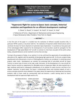
Figure 2: Momentum of a gas particle in Newton assumption [2]
In order to valuate the forces and the moments acting
on a hypersonic vehicle, it is necessary to know the six
aerodynamic coecients for the drag CD , the lateral
force CS , the lift CL , the roll moment Cl , the pitch
moment Cm and the yaw moment Cn . These coecients are depending on the shape of the vehicle and
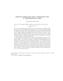
on the direction of the air ow, that can be dened as:
This behavior of the hypersonic ows leads to one
of the key hypotheses of the algorithm [2]. The ows
tends to change almost instantaneously its direction
from the free-stream orientation to a direction tangential to the surface and with this consideration it's pos
T sible to simplify the study of the phenomena. In fact
V̂∞ = − cos(α) cos(β) − sin(β) − sin(α) cos(β)
it is possible to write an approximate denition of the
(1) velocity vector over the body surface, which is found
where α is the attack angle and β is the side-slip an- by considering the velocity on the body only with the
gle, referred to a body reference frame, as shown in tangential component of the free-stream velocity [2]:
Figure 1.
Vbody−local = Vk = V∞ − V⊥ = V∞ + (n̂ · V∞ ) · n̂
(2)
where Vbody−local = Vk means that the velocity vector
considered on the body has only the tangential direction and it is possible to consider the normal component of the velocity as V⊥ = − (n̂ · V∞ ) · n̂, for n̂ the
outward normal vector to the surface of the body.
With this hypothesis it is possible to make two assumptions:
• it is necessary to know the velocity eld on the
vehicle's surface for characterize the ow, so the
forces that act on the body [2]
• it is possible to obtain the inviscid pressure on the
vehicle's surface, simply by considering the loss
of normal momentum in the almost instantaneous
change of ow direction from normal to tangential. This is the fundamental hypothesis of Newton method [2].
Figure 1: Body-axes reference frame [7]
In order to develop the analytic calculation of the
aerodynamic coecients, the Newton theory of the hypersonic ight regime is analyzed. The results can be
compared with the ones given from an usual computational uid mechanics (CFD) approach, that studies Starting from the second assumption, it is possible
the evolution of the ux around the body solving nu- to dene the pressure coecient for the Newton ow
merically the Navier-Stokes equations.
model, only dependent on the relative inclination that
the surface has with the free-stream [1]:
2.1
Newton method
Cp =
At the base of the Newton theory for the hypersonic
ux, the motion of the uid is described as a system
of particles traveling in rectilinear motion that in case
of striking a rigid surface, they lose all the momentum
normal to the surface conserving only the momentum
tangential to the surface as it is shown in Figure 2.
p − p∞
1
2
2 ρ∞ V∞
= 2 sin2 (θ)
(3)
Using conventional aircraft body axes show in Figure 1 and the corresponding free-stream velocity vector
V∞ , dened in Eq.(1) as function of angle of attack
α and side-slip β , the aerodynamic force coecients
along the body axes are [1]:
2
of the wetted surface, depending on the angle of attack and side-slip of the velocity. So it is required a
¨
¨
CD
nˆx
preliminary study for xing the limits of the integra1
1
CS =
df =
Cp nˆy dA
tion, [umin , uM AX ] and [vmin , vM AX ]. The solution of
Aref S
Aref S
CL
nˆz
this problem is not trivial, especially if the surface is
(4) parametrized with trigonometric functions. For this
and for the moments [1]:
region only convex shapes are supported.
The reference area and reference length for each
shape
are computed based on the parametrization
Cl
˜
1
used.
The
reference area is computed as the projected
Cm =
r × df =
Aref lref
S
area
of
the
shape on the y − z plane, considering the
Cn
(5) entire surface unshadowed α = β = 0. For composted
(r×n̂)x
˜
shapes, Aref is always the projected area of the biggest
= Aref1lref S Cp (r×n̂)y dA
section.
The reference length is computed as the max(r×n̂)z
imum span of the vehicle in the x direction [1].
The position vector r denes all the points of the surAs demontrated in this section, one fondamental reface A by a parametrization it two variables (u, v) [1]. sult of the Newton ow theory is that every aerodynamic coecient is derived from the surface integral
T
r = f (u, v) g(u, v) h(u, v)
(6) of the pressure coecient. So for more complex noses,
the global coecients can be calculated superpositionwhere f (u, v), g(u, v), and h(u, v) describe the x, y ,
ing the eects of each basic shapes in which is possible
and z location of a point on the surface of the vehicle
to divide the nose.
as a function of the surface parametrization (u, v).
As already introduced at the beginning of this chapOne of the most important choice of the designer
ter,
common hypersonic vehicles can be determined
is on the type of parametrization used. In fact the
through
superposition of basic shapes. For example,
selection of (u, v) parameters dramatically aects the
sphere-cones
can be constructed using a spherical segpossibility of having a closed-form solution for the inment
and
a
single
conical frustum, and bi-conics can be
tegrations [1].
constructed
using
a spherical segment and two conical
Additionally, due to the convention adopted on the
frustums
ans
so
on.
surface outward-normal n̂, the choice of u and v also
Each basic shape used will likely have dierent refinuences the expression for the dierential area dA of
erence
areas and lengths. Therefore, the superposithe integrations. So the outward-normal vector to the
tioning
of basic shapes cannot be performed by simply
surface can be dened as [1]:
adding the aerodynamic coecients from each shape.
ru × rv
Rather, the aerodynamic coecients of each basic
n̂ =
(7)
shape must be scaled to a common reference area and
kru × rv k
length.
∂r
∂r
where ru = ∂u
and rv = ∂v
are the partial derivative
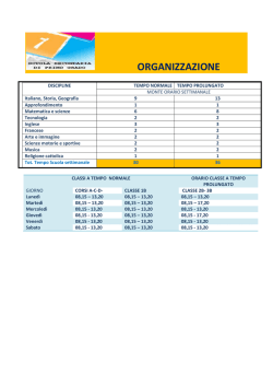
Analyzing the simple sphere-cone nose shown in Figand it is possible to dene the dierential area as dA =
ure 3, the drag coecient CDSC , for example, is calcukn̂k = kru × rv k.
lated using the superposition of the eects, where the
Dening sin(θ) = V∞ · n̂, so as a relation between
reference area is the base area of the sphere-cone and
the normal vector and the velocity of the free-stream,
the reference length is the length of the entire nose [1].
it is possible to obtain a new denition of the pressure
coecient:
2
2
ru × rv
Cp = 2 sin (θ) = 2 V̂∞ · n̂ = 2 V̂∞ ·
kru × rv k
(8)
As the particles are supposed to move straight and
to change their direction only when impacting a surface, on the back side of a plate there would be no
impact at all. So for the region of the body which does
not impact directly the hypersonic ow Cp = 0, that
means no modication on free-stream pressure. This
is called shadow region. In order to evaluate the shadowed region in which Cp = 0, it is necessary a study
2
Figure 3: Side and front view of sphere-cone
CDSC = CDC
3
ArefC
ArefSP
+ CDSP
ASC
ASC
(9)
Eq.(9) is only valid only if the ux is studied with the
1
1
∂u
Newton model. In this case only shape that makes the
+ u · ∇u −
4u + ∇p = g
(16)
∂t
Re
ρ
nose add its contribution to the total value of the aerodynamic coecient. This approach permits to create
V l
in which the Reynolds number is Re = ∞νref .
several hypersonic noses just composing a little number
In the FreeFem++ environment Eqs.(15-16) are
of basic shapes.
solved numerically with nite element in order to simulate the hypersonic ux around a 2D shape and nding
2.2
Navier-Stokes method
the eld of velocity and pressure, it is easy
to evalup
2
−
1
for
ate
the
pressure
coecient
as
C
=
2
p
γM
p
The Navier-Stokes equations describe the motion of
∞
∞
comparing
with
the
one
given
by
the
Newton
theory.
uid substances. These equations arise from applying
Newton's second law to uid motion, together with the So the 2D drag coecient can be calculated, having
assumption that the stress in the uid is the sum of a from the simulation a value of Cp and due to the symdiusing viscous term (proportional to the gradient of metry of the problem, the 3D drag coecient is obtained:
velocity) and a pressure term.
They describe the conservation of mass, momentum
ˆ
2π
and energy of all the particles in a limited system.
CD3D = 2πCD2D =
Cp
n̂x du
(17)
lref
∂Σ+
They can be expressed in the general form as [3]:
where ∂Σ+ is the upper boundary of the 2D shape.
∂ρ ∂(ρui )
+
= 0 (10)
∂t
∂xi
∂ρui
∂(ρuj ui ) ∂τij
∂p
+
−
+
= 0 (11)
∂t
∂xj
∂xj
∂xi
One of the goals of this work is to obtain analytical
expressions for the aerodynamic coecients. Having
∂
∂T
∂
∂(ρE) ∂(ρuj E)
+
−
k
−
(τij ui ) = 0 (12)these expressions, the optimization process can be done
∂t
∂xj
∂xj
∂xj
∂xj
analytically.
In mathematical optimization, constrained optimizain which the Eq.(10) denes the conservation of
mass, Eq.(11) the conservation of momentum, equa- tion is the process of optimizing an objective function
with respect to some variables in the presence of contion Eq.(12) the conservation of energy.
In the study of uid mechanics, numerical methods straints on those variables.
In this work the objective function is the drag coefsuch as the nite element and nite dierence methods
∗
∗
are often used to approximate the uid ow problems. cient CD or the ballistic coecient B = B (CD ) =
m
Considering an incompressible ux, ρ = const, and an CD Aref which are to be minimized.
inviscid ux, µ = 0, it is possible to reduce the comConsidering a problem of constrained optimization
plexity of the Navier-Stokes equations. The resulting for an objective function f (x), generally it is expressed
formulation is called Euler's equations and can be writ- as [11]:
ten in vector form as [13]:
n
find min f (x), x ∈ X ⊂ R
∇·u=0
(13)
(18)
hj (x) = 0,
j = 1, ..., l
gi (x) R 0,
i = 1, ..., m
∇u
ρ
= ρg − ∇p
(14) in which x ∈ X ⊂ Rn are the unknowns of the
Dt
problem that are limited to the space X ⊂ Rn by
3 Shape optimization
A solution of the equations is obtained with
FreeFem++, a free numerical integrator of PDE, using nite elements.
Let's consider an approximate model of the Euler's
equations, namely the pseudo-compressible approximation, or pseudo-compressible Stokes equations, where a
pressure term is added to the continuity equation with
a coecient ε and introducing the kinematic viscosity
ν = µ/ρ can be written in a dimensionless form as [12]:
∇ · u + εp = 0
the constraints, h(x) and g(x) are respectively the
equality and inequality constraint functions.
So
the space of the feasible solutions is dened as X =
{x ∈ R : gi (x) ≤ 0, i = i = 1, ..., m, hj (x) = 0, j = 1, ..., l}.
For the case of having f (x) = CD (x), the objective function is often non-linear. A possible solution
can be dening the optimization problem with the
Karush-Kuhn-Tucker (KKT) conditions, solved with
the Newton-like interior point method.
As a design choice, three inequality constrains are
selected, in order to solve the problem with the internal
(15)
4
MAXIMUM HEAT
In case of having a blunted
conguration, it is necessary to x the maximum heat
rate q̇M AX that the material can aord. By denition,
the heating rate exchanged with the aircraft and the
Earth atmosphere q̇ in [W/m2 ] that can be expressed
with the empirical formulation [9]
r
ρ∞
3
(23)
q̇ = 1.83 · 10−4 V∞
rn
point method. So for the considered case l = 0 and
m = 3.
It is important to notice that in case of minimizing
the ballistic coecient B ∗ , it is necessary to dene the
mass of the entire re-entry vehicle. It can be divided
in a constant part, Mbody , and a part depending on the
shape of the nose, m(x) = Slat (x)ρt, where Slat is the
lateral surface of the nose, ρ is a mean density of the
nose, t is a mean thickness. So the ballistic coecient
can be expressed as:
B∗ =
Mbody + Slat (x)ρt
Mbody + m(x)
=
CD (x)Aref
CD (x)Aref
in which rn the vehicle's nose radius. This approximation is only valid in hypersonic ight regime and it is
generally used for the rst estimations of the heat ux.
So the second inequality constraint, that imposes that
the heat ux have to be lower than the maximum is
(19)
−4
g2 = 1.83 · 10
3
V∞
r
ρ∞
− q̇M AX ≤ 0
rn
(24)
A value of q̇M AX = 120 kW
m2 is set as default. This is
the limit value for a non-ablative shield of a re-entry
vehicle [10].
Of course in the unblunted conguration this condition is not taken into account.
TOTAL MASS
Figure 4: Constrains on the cargo volume (a) and on
the nose mass (b)
The optimization process has to
maintain or even reduce the mass of the nose m∗ . As
shown in Figure 4(b), the mass of the nose can be simIt can be useful to dene a in- ply dened as
ternal volume that has to be maintained during the
m∗ = Slat ρt
(25)
optimization process. In fact the noses of the launchers are often used for containing the payload, so it is The lateral surface is a function of the geometrical feanecessary to maintain a certain volume for the cargo. tures of the nose so it can be expressed as
It is considered a cylindrical volume with height Lvol
s
2
2
ˆ
and radius Rvol , so V ol = πLvol Rvol
, as shown in Figdf (x)
ure 4(a). As design parameter is chosen the height of
Slat = 2π
f (x) 1 +
dx
(26)
dx
the volume, that corresponds at a radius, using the
Lf ig
equation of the nose shape f (x):
so the third inequality of the optimization problem can
Rvol = f (x = Lvol )
(20) be written as
CARGO VOLUME
where Lvol ≤ lref and with simple geometrical cong3 = Slat (Lf ig , Rf ig )ρt − m∗ ≤ 0
(27)
sideration is possible to dene the volume high as a
Having dened the three inequality constraints of the
function of the longitudinal dimension of the shape as
optimization problem, it is important to notice that all
Lvol = Lvol (Lf ig ).
So xed the cargo volume V ol∗ , the optimization the constraints and the objective function too are nonprocess has to change the shape of the nose maintaining linear.
or improving this internal volume.
4 Bi-conic blunted nose
(21)
2
g1 = πLvol Rvol
≥ V ol∗
The calculation of the aerodynamic coecients and the
shape optimization process are made for several type
of hypersonic shapes: conic, bi-conic, ogive, parabolic
and Bézier curves noses in blunted or in unblunted conguration. In this section the results obtained for a
bi-conic blunted conguration are presented.
and substituting in Eq.(21) the Eq.(20) it is possible
to obtain the dependence of the inequality constrain g1
from the geometrical variables Lf ig ,
2
g1 = V ol∗ − πLvol (Lf ig ) (f (Lvol (Lf ig ))) ≤ 0
(22)
5
The geometrical design parameters of the cone are
The integrations are performed with the help of
dened by the length along the axis of revolution LcIi Mathematica.
and LcIf , by the beginning radius RcIi and the ending
Following the same process, the coecients for the
radius RcIf , in which the notation cI is referred at the spherical termination are obtained, for a parametrizacone I. So the cone half-angle is easily dened as δcI = tion made by:
RcI −RcI
arctan LcI i −LcIf . The same relations are valid for
(
f
f
u = δ, δ ∈ [0, π2 − δtan ]
the second cone too, following the Figure 5.
(31)
v = ω, ω ∈ [0, 2π]
The surface of the cone is parametrized by:
(
u = z(x) = r(x),
v = ω,
r ∈ [RcIi , RcIf ]
ω ∈ [0, 2π]
in which ω is the revolution angle and δ is the nose
angle. With the parametrization of the curve:
(28)
xc + rn cos(u)
r = rn cos(v) sin(u)
rn sin(v) sin(u)
in which ω is the revolution angle as shown in Figure 5.
The equation of the semi-cone in the x − z plane is
z(x) = −x tan δc + RcIi
(29)
(32)
the aerodynamic coecients are obtained.
where δsp = π2 − δtan and as aspected due to the
symmetry of the shape, the roll moment coecient is
always equal to zero.
An important issue of the Newton theory for the
So the position vector is dened as
hypersonic ight is the denition of the shadowed area.
In that area the ux doesn't interact with the shape, so
consequently the pressure coecient is equal to zero,
h
iT
R
r = − tanu δc + tancIδic u cos(v) −u sin(v)
(30) Cp = 0.
So by denition, it's necessary to dene the tangency
Eq.(30) is used in Eq.(7) for evaluate the pressure coef- condition of the ux, for the given V∞ . First it is decient and then integrated along the surface obtaining ned the slightest inclination of the shape, by the angle
δmin . Then there is a portion of the shape shadowed,
the following aerodynamic coecients:
only if it is satised this condition:
Figure 5: Side and front view of bi-conic cone
parametrization
max{α, β} > δmin
(33)
If the condition of shadowed area, Eq.(33), is satised, the ux interacts only with an half of the shape.
Cutting the shape with a plane y−z , it's obtained a circle dened by the angle ω . Projecting the components
of the air speed, Vy = − sin β and Vz = − cos(β) sin(α)
on the y − z plane, it is possible to identify the direction of the velocity in this plane. The velocity vector
in the y − z plane can be dened with as:
cos(β) sin(α)
ωi = arctan
(34)
sin(β)
6
So nally the half of the shape wetted by the ux,
so unshadowed for an arc of π , is given by v ∈ [ωi −
π
π
2 ; ωi + 2 ].
In case of having a blunted nose, so if the nose has
a spherical segment at the end, an other assumption is
necessary. Due to the parametrization chosen for this
surface, the parameter u = δ denes the half-angle of
the spherical segment. For this segment the δmin is
given by the tangency of the spherical segment with
the backward part of the nose. So in case of that the
shadow condition is satised, Eq.(33), the unshadowed
surface of the spherical segment on the x − y or x − z
plane, is given by u ∈ [0 ; max {α, β}].
In case of having a back part of the body with a
dierent inclination, can happen that even if one part
of the nose has shadowed areas, not all the nose has.
Figure 6 shows the possibility to have the second part
of the nose unshadowed, due to its higher inclination.
Then a comparison with the simulation of the Stokes
equations is made.
For the Navier-Stokes problem, an hypersonic ux at
Mach=6 have been analyzed, in a Stratosphere conditions of pressure, density and temperature, according
to the ISA standards as presented.
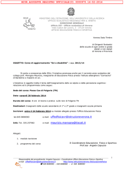
Figure 7: Diagram of CD ∝ α for the three dierent
methods, conic nose
The standard deviation of each coecient has been
calculated for testing the validity of the analytical approach. The results obtained with the analytical approach are perfectly conrmed by the panel method,
with a dierence less than 1.15·10−3 %. This is because both are derived from the Newton theory for the
hypersonic ux. A bigger local deviation of the dates
has been registered comparing the analytical approach
with the solution given by the Navier-Stokes method.
Figure 6: Partially shadowed condition for a bi-conic As aspected, with all the approximations done for computing the Navier-Stokes equations, the results aren't
nose
extremely precises, so even the tting with the analytic
dates can't be perfect. Evaluating the drag coecient
The unshadowed area can be dened geometrically
for a quite wide range of angle of attack, the standard
by the interaction of the velocity vector and the back
deviation between the two approaches results globally
part of the nose as:
less than 26%.
(
This result can be due to the fact that the conilref tan(max{α,β})−RcIi
xnoS = (tan(max{α,β})−tan
δcI )
cal
nose can be described in a 2D geometry as two
(35)
znoS = RcIi − xnoS tan δcI
plates. For this geometrical reason the Navier-Stokes
equations give a similar result to the panel method beDened the possible shadowed regions of the nose,
cause in both of the approaches the shape analyzed can
the coecients are calculated following the superposibe reduced to a sum of plates. However, since that the
tion of the eects as:
Newton method doesn't take into account turbulence
or eventual presence of ux separation, surely present
CD = CDcI + CDcII + CDS
with higher angle of attack, improving the free-stream
CS = CScI + CScII + CSS
inclination, the two methods give more dierent reCL = CLcI + CLcII + CLS
(36) sults.
Cl =
ClcI + ClcII + ClS
Cm = CmcI + CmcII + CmS
Compared Methods
%
Cn = CncI + CncII + CnS
Analytical/Panels
1.15·10−3
The results obtained analytically are rst conrmed
Analytical/Navier-Stokes
25.5
calculating the coecients numerically with the panel
method. This method penalizes the surfaces in lami- Table 1: Standard deviation of the analytic dates, comnar plates and computes numerically the coecients. pared with the numerical results for the conic nose
7
Conguration
Bi-conic (blunted)
With more complicated shapes as the ogive,
Fixed parameters [m]
RcIi = 5
parabolic or Bézier noses the gap between the values
L∗cI = 1 → 0.394
of the analytic approach and the Navier-Stokes simu∗
∗
RcI
= RcII
=4→5
i
f
lation is bigger.
Free parameters [m]
∗
LcII = 3 → 2.4
However the rst big advantage on the analytic ap∗
RcII
= 2.5 → 0.653
f
proach is demonstrated, the computational time of the
∗
∗
B → Bopt
667.3 → 250.1
numerical method results an order of magnitude big% reduction
70.8
ger than the other. In fact the simulation of the ux
can take tens of second, while the calculation of the Table 3: Results of ballistic coecient optimization for
coecients via the analytic equation is instantaneous. conic nose family
The second advantage of having an analytic expression is that is can be used as objective function for a
constrained optimization problem. The results of the
minimization of the drag coecient are presented.
Table 2 denes the geometrical features and the values of the drag coecients after and before the optimization.
Conguration
Fixed parameters [m]
Bi-conic (blunted)
RcIi = 2.5
L∗cI = 2 → 1.009
∗
∗
RcI
= RcII
= 2 → 2.340
i
f
L∗cII = 3 → 2
∗
RcII
= 1 → 1.866
It is important to underline that the optimization
process not always converges. In fact it is necessary
Free parameters [m]
to introduce geometrical parameters that are already
close to the optimal shape in order to have a startf
CD → CDopt
0.4498 → 0.4304
ing point that allows the convergence. Generally it
% reduction
4.3
is enough to check that the radius of the blunted
part is satisfying the constraint on the heat ux, so
Table 2: Results of optimized drag coecient for bi- q̇(r ) < q̇
n
M AX . Moreover a limitation on the reducconic nose
tion of not more than 80% on the length of the nose
has been imposed.
The optimization achieves a reduction of the drag
coecient around the 4.5%. It is obtained reducing
the length of the nose in order to obtain a shape more
The results conrm that the spherical termination
cylindrical, respecting the limitation on the mass and
the cargo volume. Reducing the inclination of the cone, gives the bigger contribute to the drag, but the coneven the surface exposed to the normal part of the ical part is the one that inuences more the result.
velocity eld is reduced, so globally the drag can be With a study on the sensitivity of the geometrical parameters, it can be easily demonstrated that the cones
lower.
parameters inuence more the nal solution. In order
to minimize the ballistic coecient or maximizing the
drag, the spherical part is reduced until the heat ux
constraint is valid, due to maximizing the conical part.
A physical interpretation of this behavior is given by
the Newton model itself, from which the coecients are
calculated. In fact for improving the drag it is necessary a higher pressure coecient. It is calculated from
Figure 8: Blunted bi-conic nose with drag coecient the loss of normal momentum of the free-steam partiCD optimized, in design (a) and optimized congura- cles that hit the shape. It is easy to notice that having
tion (b)
a bigger conic portion of the nose, with an higher angle δc , the normal collision of the particles along the
Table 3 denes the geometrical features and the val- nose results more eective. In fact for the relative anπ
ues of the ballistic coecients after and before the op- gle θ that tends to 2 , the pressure coecient increases,
2
timization.
Cp = 2 sin θ.
8
by the analytic calculation. This is due to many factors: rst of all, methods as nite dierences or nite
volumes are usually preferred for solving the NavierStokes equations. Moreover the simplications made
on the equations and on the ux model don't allow the
results to be very precise. In fact the density of the
ow is considered constant (or semi-constant) and the
eects of the viscosity µ were ignored. Also the eects
of the temperature are not considered in the equations,
eects that are even more important when the velocity
of the ux tends to hypersonic values.
Having as objective the developing of a procedure
for the calculation of the aerodynamic coecients in
a preliminary phase of the design, the approximations
given by the Newton model are adopted. The results
of the simulation conrm the validity of this model for
high hypersonic ight condition. For lower hypersonic
Mach number the solution given by the two methods,
analytic and numerical, have a dierence up to around
25%, depending on the complexity of the shape, the
angles of attack or side-slip, the presence of turbulence
or ux separation.
However the study of the evolution of the ux by
the numerical simulation of the Navier-Stokes equations has proved the sensible advantage of having an
analytic model in terms of Cpu time, as expected. In
fact the results of the analytic calculation are obtained
in fractions of second, while the ones given by the numerical simulation can take tens of seconds, with a
lower precision for the considered model of the ux.
Saving computational time is fundamentally important in a preliminary phase of the design of a hypersonic vehicle, in which is usually preferred obtaining
faster results and in which is important to understand
which are the better design choices, taking into account
an higher level of approximation. Moreover, by the implementation of the analytic model in the FreeFem++
environment, the code results completely free, instead
of the commercial codes, and there is the open possibility to improve the numerical model in order to obtain
an higher level of details in the evolution of the hypersonic ux. In fact, the implementation of the Euler's
equations results inappropriate for describing the hypersonic regime and a better model for the evolution of
the ux have to be developed for obtain higher delity
results in the numerical simulation.
Finally, the analytic expressions of the aerodynamic
coecients allow to build a simple but very eective optimization procedure. The analytic formulations permit to solve the problem of minimizing the drag or the
ballistic coecient, solving a constrained optimization
problem. Due to the high non-linearity of the equations, the solution was obtained using the Newtonlike internal point method. This algorithm was implemented in Mathematica and can be added in the
Figure 9: Blunted bi-conic nose with ballistic coecient B ∗ optimized, in design (a) and optimized conguration (b)
5 Conclusions
Noticing that generally the noses of the hypersonic vehicles can be often referred to simple shapes of revolution, the aerodynamic coecients of some basic shapes
were calculated, following the Newton theory for the
hypersonic regime. Often, the integration of the pressure coecient along the dierent surfaces is not a trivial problem. The integrations have been done with the
help of the software Mathematica. It is necessary to
underline that the selection of the parametrization of
the shapes strongly inuences the possibility of obtaining an analytic solution. Although Mathematica is a
very powerful software, human insight was still critical to obtain the formulation of the aerodynamic coecients.It was often necessary to add mathematical
assumptions to the integrals and model the equations
in order to obtain the analytic expressions of the coefcients.
A model of superposition of the eects [1] was
adopted in the case of the Newton theory to determinate the coecient of composed shapes. With this
model each shape gives its contribution to the total
value of the aerodynamic coecient so conic, bi-conic,
ogive, parabolic and Bézier noses have been analyzed
in unblunted or blunted conguration, that is made
adding a spherical termination to the nose. In this papaer only the the blunted bi-conic nose is presented.
Validated the results from the analytic approach with
the panel method, the formulation of the aerodynamic
coecients was also implemented in FreeFem++.
The FreeFem++ environment allows having a completely open-source code for the calculation of the aerodynamic coecients for hypersonic vehicles and allows to simulate the ux along the shapes, using nite
elements to solve the Navier-Stokes equations. The
solution given by the numerical simulation however
presents sometimes a sensible gap with the values given
9
FreeFem++ code too. The results of the optimization
[7] Antonio Vitale, Federico Corraro, Guido De Matare in some cases very eective, reaching generally up
teis and Nicola de Divitiis. Identication from
to 70% of reduction in the ballistic coecient, up to
ight data of the aerodynamics of an experimental
4% of in drag coecient, for the analyzed case.
re-entry vehicle. Dr. Chaoqun Liu (ed.). Arlington, Texas, 2012.
In conclusion, in this work is presented an interesting
approach on the hypersonic aerodynamic coecients,
obtained in an analytic way that allows its optimiza- [8] F. S. Milos, Y.-K. Chen, T. H. Squire. Analysis
of Galileo Probe heatshield ablation and tempertion, depending on the goals. The advantage in terms
ature data. JOURNAL OF SPACECRAFT AND
of computational time is shown in comparison with the
ROCKETS, Volume 36, Number 3. Moett Field,
numerical simulation. The biggest advantage of having
California, 1999.
analytic expressions consist in the possibility of implementing directly the coecients in the study of the [9] Dominic Dirkx, Erwin Mooij. Continuous aerooptimal condition needed, obtaining good results.
dynamic modeling of entry shapes. AIAA AtmoAs open future develops, it is possible to implement
spheric Flight Mechanics Conference, 8-11 Authe existing database of the studied shapes, adding
gust. Portland, Oregon, 2011.
new or creating new combinations. Having already
a FreeFem++ code, it could be possible to improve [10] Peter A. Gnoo. Planetary-entry gas dynamics.
Annu. Rev. Fluid Mech, Volume 31, Pages 459the uid model governed by the Euler's equations,
494. Hampton, Virginia, 1999.
in order to obtain a numerical model that better describe the evolution of the hypersonic ux. Finally, the
[11] Alessandro
Agnetis.
Introduzione
Internal Point algorithm can be implemented in the
all'ottimizzazione vincolata. Lecture notes,
FreeFem++ environment, obtaining a complete openUniversità di Siena. Siena, 2013.
source software for the calculation of the aerodynamic
coecients and the shape optimization for a wide range [12] Florian De Vuyst. Numerical modeling of
of hypersonic vehicles.
transport problems using FreeFem++ software.
Phd thesis, Department of Mathematics-ENS
CACHAN. Paris, 2013.
References
[13]
[1] Michael J Grant. Rapid simultaneous hypersonic
aerodynamic and trajectory optimization for conceptual design. Phd thesis, Georgia Institute of
[14]
Technology. Atlanta, 2012.
[2] Francesco Villa. Algebraic models for aerodynamic coecients calculation during the atmospheric re-entry. MSc thesis, Politecnico di Milano.
Milano, 2011.
[3] Gianluca Iaccarino. Solution methods for the
incompressible Navier-Stokes equations. Lecture
notes, Standford University. Standford, 2008.
[4] Florian De Vuyst. Numerical modeling of
transport problems using FreeFem++ software.
Phd thesis, Department of Mathematics-ENS
CACHAN. Paris, 2013.
[5] Luca Dedè. Adaptative and reduced basis methods for optimal control problems in environmental applications. Phd thesis, Politecnico di Milano.
Milano, 2008.
[6] Jack Moran. An Introduction to Theoretical and
computational aerodynamics. Dover publication,
New York, 1984.
10
Leonardo Rubino. EQUAZIONI DI NAVIERSTOKES: la regina della uidodinamica. Scribd
Inc. Torino, 2010.
F. Hecht. New development in freefem++. Journal
of Numerical Mathematics, Volume 20, Issue 3-4,
Pages 251266. Paris, 2013.
© Copyright 2026 Paperzz