A Novel Membrane Finite Element with
Drilling Rotations
Reijo Kouhia
A new low order membrane nite element
is presented. The element formulation is based on the
variational principle of Hughes and Brezzi employing
an independent rotation eld. In the present work nonconforming interpolation is used for the drill rotation
eld. Both triangular and quadrilateral elements are
considered. Combined with the Reissner-Mindlin plate
bending element of O~nate, Zarate and Flores, where
the rotations are interpolated by nonconforming functions, results in a simple shell element with three translational displacements at corner nodes and three rotation components at the midpoints of the element edges
as degrees of freedom.
Abstract.
1
INTRODUCTION
In-plane rotational degrees of freedom, \drilling degrees of freedom", are particularly convenient in the
analysis of shells. Typical shell elements have three
translational and two rotational degrees of freedom at
a node. This results in many diculties of model construction and of programming and numerical ill - conditioning for certain types of element assemblages. Thus
the presence of all three rotations at a node is advantageous from practical point of view.
Early attempts to construct membrane elements with
drill rotations have been unsuccessful. Allman [1] and
Bergan and Felippa [2] formulated successful membrane elements with drill rotations by using special interpolation patterns. Allman derived the interpolation
scheme by choosing the normal and tangential displacement components to be quadratic and linear functions,
respectively. The only deciences of this remarkably
simple element are the existing zero energy mode and
that the vertex rotations are not true rotations. These
shortcomings were removed in a later development by
Allman [3], at the expense of having a cubic displacement eld. Bergan and Felippa used the so-called free
1 Laboratory of Structural Mechanics, Helsinki University
of Technology, Rakentajanaukio 4A, FIN-02150 Espoo,
e - mail: Reijo.Kouhia@hut.
c 1996 R. Kouhia
ECCOMAS 96.
Published in 1996 by John Wiley & Sons, Ltd.
1
formulation of the nite element method to derive their
element.
Recently, Hughes and Brezzi [4] presented a simple
and beautiful variational formulation, which employs
independent rotation eld and is also stable in the discrete case. They also proved that elements based on
their formulation are convergent for all standard interpolations including equal order interpolation for displacements and rotation. Numerical experiments reported by Hughes et al. [5] conrm the a priori theoretical convergence estimates. They compared linear
and quadratic triangular and quadrilateral elements
and also a bilinear element with incompatible modes.
Incompatible modes signicantly improve the coarse
mesh accuracy of the bilinear element. On the other
hand, the static condensation needed to eliminate the
nodeless generalized displacements is awkward, especially in geometrically nonlinear problems.
Ibrahimbegovic et al. [6] amended the displacement
interpolation of the four node quadrilateral element by
Allman type quadratic modes in order to improve the
coarse mesh accuracy of the element. This considerably
improves the bending behaviour of the element. They
also added a hierarchical bubble interpolation mode to
the displacement eld.
A convenient interpolation scheme, advocated by
Hughes and Brezzi, is to use the same functions for
both displacements and rotations. This results in an
element with equal number of degrees of freedom at
each node.
In the present study, nonconforming interpolation is
adopted for the drill rotation. Together with the nonconforming Reissner-Mindlin plate element of O~nate,
Zarate and Flores [7], it gives an element with three
degrees of freedom at each node. Thus, translational
and rotational components appear at dierent nodes.
It is argued that the increased freedom of the nonconforming interpolation is benecial to the coarse mesh
accuracy of the element, and still facilitating relatively
simple implementation.
2
coarse mesh accuracy, the in-plane displacement interpolation of the quadrilateral element can be amended
by parabolic modes linked to the drilling rotations in
the following way:
ELEMENT FORMULATION
2.1
Membrane element
The variational equation of the Hughes-Brezzi formulation in the case of Dirichlet boundary conditions has
the form
Z
u
" : C : "d
=
(1)
where " = symm ru is the strain tensor, i.e. the symmetric part of the displacement gradient and is a
skew symmetric tensor representing the in-plane rotation. The fourth order tensor C contains the material
parameters and the body force vector is denoted by f .
An appropriate value of the regularizing penalty parameter is chosen in accordance with the ellipticity
condition. For the isotropic case the value = (shear
modulus) seems to balance the terms in the stability
estimate and thus seems reasonable [8]. However, the
method is insensitive to the choice of the penalty parameter in the region 0 < . Since the formulation
above is extensively studied in Refs. [4],[8], the details
are not repeated here.
Two interpolation schemes of the present element
are considered. The rst one is the standard linear or
bilinear continuous interpolation for the translational
displacements with nonconforming interpolation for the
drilling rotation:
n
X
v=
Nu;
=1
2n
X
i
i
=n+1
n
X
=1
N 5 ( ) = 1 0 2 ;
N
nc
i
i
4s
2
1
86 62
1
s16
2X2 XXz
8 s
1
2 57
1
2
1
s
1 XXXXXX
s22 XXX 11
X s1
5
n
y
i
i
i
i
(2)
;
i
If the conventional conforming interpolation is used
for the drill rotation, then the Allman-type amendment
for the in-plane displacement components can be used
for both the triangular (n = 3) and the quadrilateral
(n = 4) element:
n
X
=
u
=1
N (; )q
i
i
i
+
i
n
X
=1
i
N + (; ) L ( + 0 )n
8
n
i
i
i
i
i
(7)
3T
2
is the unit outward
where n = cos sin normal vector of the element edge i.
i
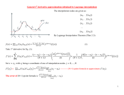
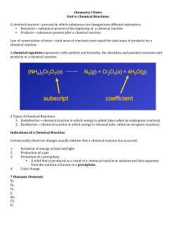
Plate Formulations and Problems
A quadrilateral element.
Figure 1.
i
i
i
2
x
i
nc
i
1s
1
3
n
where n is the number of vertex nodes. In the second
approach the displacement interpolation is amended by
parabolic modes linked with the rotation.
For the triangular element the nonconforming interpolation at edge i (connecting nodes i and i+) is simply
(3)
N =L +L + 0L 0
where L is the area coordinate associated with node i.
Nonconforming interpolation for the quadrilateral element is obtained by rotating the bilinear interpolation,
resulting in
N = 41 [1 + 2 + 2 + ( + ) 04 ( 2 0 2 )]; (4)
where and (i = 5; :::; 8) are the nodal point coordinates in the parent element. In order to improve the
i
(6)
s
2
Nv;
i
N 6 ( ) = 1 0 2 :
7
i
nc
i
(5)
For the triangular element such an enhanced interpolation is not possible.
i
i
=
i
i
1 u d
u =
i
where q contains the nodal translational (u; v)-degrees
of freedom and N1 ; :::; N4 are the standard bilinear interpolation functions. The unit vectors n57 and n86 are
normal to the lines connecting the nodes 5 and 7 and
8 and 6, respectively, see Fig. 1. The parabolic incompatible modes N5 and N6 are dened as
f
N (; )q + N5 ( ) L86 ( 8 0 6 )n86
8
+N6 () L857 ( 7 0 5 )n57;
+ (skewru 0 )(skewru 0 )d
=
=1
i
Z
Z
4
X
i
2
i
i
R. Kouhia
2.2
The tangential shear strain is constant at each ele-
Plate bending element
ment edge
Combining the membrane element described above with
the nonconforming Reissner-Mindlin plate bending element introduced by O~nate, Zarate and Flores [7], results in a facet shell element where the translational
degrees of freedom are located at the vertex nodes and
the rotational degrees of freedom at the midside nodes.
In order to avoid shear locking, the MITC type of reduction operator is used to evaluate the shear strains.
The reduction gives constant tangential shear strains
on element egdes, which are set to be equal to the shear
strains obtained from the original displacement variables at the midpoints of element edges.
s
BB
MB 0
B1
0
BB
0
uPPP
PPP B
i0
PPPBui
-- --
??
66
si
y
y
x
x
w =
n
X
=
x
=n+1
nc
i
xi
y
i
where
S
x
n
X
=1
i
i
S
xi
=
S
y
n
X
i
i
=1
N + 0 S 0S N E
i
i
1
i
i
xi
i
0 SE+ C N + ;
i
1
i
i
+
yi
i
(12)
N : (8)
nc
i
S
yi
i
i
i
i
i
;x
i
S
x
= 1 + kt
(14)
(h=t)2 (w 0 );
where is a positive stabilization factor, t is the thickness of the plate and h is a characteristic length of an
element, i.e. the length of the longest edge.
The behaviour of this simple nonconforming ReissnerMindlin plate bending element is not particularly good.
Mathematical analysis also reveals that the triangular
element is not convergent for a xed plate thickness,
as shown recently by Arnold and Falk [9]. However,
optimal order convergence, uniform in t, is obtained
if the plate thickness t tends to zero as the mesh is
rened. Thus the element exhibits an unusual type of
locking. Perhaps, some technique can remove this deciency. Some preliminary calculations by the triangular
element with constant shear, evaluated from the original displacement variables, have shown better performance. However, mathematical analysis is needed to
assess the applicability of this element.
In a triangular case there is an interesting connection
of this nonconforming Reissner-Mindlin plate element
to the well known Morley's constant moment Kirchho plate element [7], [9]. Morley's element [10] can
be obtained from interpolations (8) by enforcing the
Kirchho constraint at the midpoints of the element
edges. Thus one of the two rotation components can
be eliminated.
yi
(9)
i
Here, N 's are the standard linear/bilinear interpolation functions. Note, that this interpolation is dened
separately in each element. The additional rotation
eld (9) gives two additional degrees of freedom for
each edge. They can be eliminated using the following
two conditions:
i
Plate Formulations and Problems
i
i
x
N :
i
yi
i
E = C S 0 0 C 0S ;
(13)
and C ; S are abbreviations for cos ; sin .
In the stabilized nite element methods for the
Reissner-Mindlin model, shear forces are computed from
the expressions
kt
Q =
1 + (h=t)2 (w 0 );
i
N ;
i
1
i
i
i
N
xi
0 CE++C N + ;
i
E+
=1
i
i
n X
0 Si+ Si
E
ni
N
1
i
i
i
i
0 Ci Si0
See Fig. 2 for the denition of the rotations. A convenient way to implement the shear reduction operator
is to dene a new rotation eld from which the shear
strains are evaluated, i.e.
=
=1
i
y
=n+1
i
=
S
y
Q
2n
X
=
T
N 0 C 0S N E+ +
E
i
i
N ;
(10)
S
;s
n X
0 Ci+ Si
E
y
i
=
S
x
0 Ci Ci0
Nw;
=1
2n
X
S
i
Notations.
i
T
S
The standard linear or bilinear interpolation is used
for the deection but nonconforming one for each rotation component and :
x
T
;s
y
Figure 2.
0s ;
displacement elds at the midpoints of the element
edges
(11)
w 0 s = w 0 s (0):
The resulting form of the rotation is
i
x
;s
and is equal to the shear evaluated from the original
i+
u
0B
00
=w
3
;y
S
y
R. Kouhia
3
EXAMPLES
3.1
A cantilever beam
A shear loaded cantilever beam is a common test case
for membrane elements. The problem denition is shown
in Fig. 3. Computed tip displacements are tabulated
in Table 1, where also results of Allman [1], MacNeal
and Harder [11] and Ibrahimbegovic et al. [6] are
shown. Only a minimum number of restraints is imposed, hence no drilling degrees of freedom are restrained. The penalty parameter is chosen to be equal
to the Young's modulus. The reference solution for the
tip displacement with the properties shown in Fig.3 is
dened in Ref. [6] as
3
v = P L + (4 + 5 )P L = 0:3553:
(15)
3EI
2EH
12
16
Table 1.
uniform meshes
distorted
element
4x1
8 x 2 16 x 4
4x1
T3
0.0934 0.1977 0.2982
0.0900
T3D3
0.0851 0.1872 0.2882
0.0819
T3D3-A
0.2104 0.3170 0.3465
0.2020
Q4
0.2434 0.3180 0.3481
0.2138
Q4D4
0.2179 0.3058 0.3433
0.1988
Q4D4-A
0.3311 0.4301 0.3709
0.3230
Q4ND4 3x3 0.2250 0.3060 0.3423
0.1992
Q4ND4 4pq 0.2216 0.3050 0.3420
0.1979
Q4ND4-IC3 0.3295 0.3479 0.3550
0.2735
T3ND3
0.0855 0.1842 0.2850
0.0822
[1]
0.3026 0.3394 0.3512
[6]
0.3445 0.3504 0.3543
0.3064
[11]
0.3409
0.2978
T, Q = triangular, quadrilateral element
D = Hughes-Brezzi formulation for drill rotation
A = Allman type interpolation (7)
N = nonconforming, IC = incompatible modes (5)
3x3 = 3 by 3 Gaussian quadrature
4pq = specialpfour point quadrature
p
(i; i ) = (6 2=3; 0); (0; 6 2=3), weights 1,
integrates exactly monomials i j where i + j 3.
3 = 3x3 rule and the special four point rule give equal results
distorted mesh
12 22 12 12
BB
BB 4 22 8 20
mesh
00 j@ uniform
0
@ @ @ 6P
H8
0
0
0
j @ @ @ @
0
00
Short cantilever beam, tip deections.
H
L
E = 30000, = 0.25, P = 40, L = 48, H = 12
Figure 3.
Short cantilever beam.
1
The behaviour of the nonconforming elements is comparable to the corresponding one of the conforming elements. The nonconforming drill rotation elements are
also insensitive to the value of the penalty parameter
, see Fig.4, where the normalized tip displacements
(with respect to (15)) are shown as a function of .
The results are similar to those reported by Hughes
et al. [8]. The spectral condition number as a function
of the penalty parameter is shown in Fig. 5 for the
Q4ND4 element. Other elements based on the HughesBrezzi formulation behave almost identically. It seems
that the range 1004 < = < 1 can be used with no
danger of deterioration of numerical conditioning of the
equation system.
The nonconforming quadrilateral with incompatible
modes behaves like the elements QM6D4-1 and QM6D42 in Ref. [8] and without the incompatible modes like
Q4D4. Thus, it seems to be a promising alternative for
the membrane interpolation of a facet type shell element. It will be tested in the next example.
Plate Formulations and Problems
0.8
2 2 2 2 2222222 2 2 2 2
3 3 3 3 333
3
0.6
0.4
0.2
Q4ND4
Q4ND4-IC
0
10012 1008 1004
Figure 4.
4
1
3
33 3 3 3 3
3
2
=
104 108 1012
Normalized tip deection as a function of .
Uniform 8 2 2 mesh.
R. Kouhia
I-beam, tip deections.
Table 2.
16
lg C2 (K)
12
8
4
Q4ND4
3
3
3
3
3
3
3
3 3333
0
10012 1008 1004 1
=
3
3
3
3
element
degrees of freedom
Q4D4 + MITC4
Q4D4-A + MITC4
degrees of freedom
Q4ND4 + MITCN4
Q4ND4-IC + MITCN4
For the triangular elements, computations with constant shear stress, evaluated from the original displacement variables, are also shown. In this case the element
stiness matrix can be exactly integrated by the one
point rule.
The stabilization parameter used is also shown in Table 3. It is selected according to the results of Ref.[13]
( = 0:1 for the quadrilateral and = 0:4 for the
triangular element). It can be seen that the displacement value is inuenced on the choice of the parameter. However, one should not concentrate too much on
the accuracy of displacements, which is usually good
enough. As shown numerically by Lyly et al. [13] the
moments are practically unchanged when the stabilization parameter is varied, while the shear forces become
better when a larger value is chosen. Also some nonlinear computations done by the author suggest to use
a larger value ( = 0:4 for the quadrilateral) for the
stabilization parameter, than the one giving the minimum error for the displacement.
104 108 1012
Logarithm of the spectral condition number
of the stiness matrix as a function of . Uniform 8 2 2
mesh.
Figure 5.
3.2
A folded plate problem
A cantilever beam structure with a thin-walled I-cross
section is analyzed. Same material constants, length
and the height of the beam between the ange centroids
are used as in the previous example. The wall thickness
of all parts of the beam is chosen to be t = 0:2 = L=240,
and the width of the anges are equal to the height H .
All the shell elements compared are of at facet type,
where the membrane interpolations are as in the previous example and the plate-bending part is modelled
by the stabilized MITC type of elements, see Refs. [12],
[13].
The reference solution for the tip displacement is
computed from the Timoshenko beam theory as
3
v = P L + (1 + )P L = 0:3133:
(16)
3EI
2EHt
In the computations all dof's at the support are supressed. Only quadrilateral elements are compared and
the values for the stabilization parameters used are
= 0:1 and = .
3.3
z
P
?
diaphragm (v = w = = 0)
x
6
A pinched cylinder
The pinched cylinder with rigid end diaphragms is frequently analyzed test case to shell elements, see Fig. 6.
One octant of the shell is modelled and the normalized
displacement under the point loads is recorded in Table 3, where also some results from Refs. [14] [15], [16]
are shown. The reference displacement is [14]:
w = 164:24 P = 1:82489 2 1005 :
Et
c
Plate Formulations and Problems
uniform meshes
425
8210 16220
144
528
2016
0.2374 0.2879 0.3068
0.3003 0.3088 0.3136
204
768
2979
0.2408 0.2899 0.3095
0.3027 0.3106 0.3165
P
-
L=2
Figure 6.
-
L=2
6
x
R
?
L = 600
R = 300
t=3
E = 3 2 106
= 0:3
P =1
Pinched cylinder.
(17)
5
R. Kouhia
Table 3.
[2] P.G. Bergan and C.A. Felippa. A triangular membrane
element with rotational degrees of freedom. Computer
Methods in Applied Mechanics and Engineering, 50:25{
69, 1985.
[3] D.J. Allman. Evaluation of the constant strain triangle
with drilling rotations. International Journal for Numerical Methods in Engineering, 26:2645{2655, 1988.
[4] T.J.R. Hughes and F. Brezzi. On drilling degrees of
freedom. Computer Methods in Applied Mechanics and
Engineering, 72:105{121, 1989.
[5] T.J.R. Hughes, F. Brezzi, A. Masud, and I. Harari. Finite elements with drilling degrees of freedom: theory
and numerical evaluations. In R. Gruber, J. Periaux,
and R.P. Shaw, editors, Proceedings of the fth International Symposium on Numerical Methods in Engineering, pages 3{17, Springer-Verlag, 1989.
[6] A. Ibrahimbegovic, R.L. Taylor, and E.L. Wilson.
A robust quadrilateral membrane nite element with
drilling degrees of freedom. International Journal for
Numerical Methods in Engineering, 30:445{457, 1990.
[7] E. O~nate, F. Zarate, and F. Flores. A simple triangular element for thick and thin plate and shell analysis.
International Journal for Numerical Methods in Engineering, 37:2569{2582, 1994.
[8] T.J.R. Hughes, A. Masud, and I. Harari. Numerical
assessment of some membrane elements with drilling
degrees of freedom. Computers and Structures, 55:297{
314, 1995.
[9] D.N. Arnold and R.S. Falk. Analysis of a linear-linear
nite element for the Reissner-Mindlin plate. preprint.
[10] L.S.D. Morley. The constant moment plate bending
element. Journal of Strain Analysis, 6:20-24, 1971.
[11] R.H. MacNeal and R.L. Harder. A rened four-noded
membrane element with rotational degrees of freedom.
Computers and Structures, 18:75{84, 1988.
[12] F. Brezzi, M. Fortin, and R. Stenberg. Error analysis of mixed-interpolated elements for Reissner-Mindlin
plates. Mathematical Models and Methods in Applied
Sciences, 1:125{151, 1991.
[13] M. Lyly, R. Stenberg, and T. Vihinen. A stable bilinear element for Reissner-mindlin plate model. Computer Methods in Applied Mechanics and Engineering,
110:343{357, 1993.
[14] E.N. Dvorkin and K.-J. Bathe. A continuum mechanics based four-node shell element for general non-linear
analysis. Engineering Computations,1:77{88, 1984.
[15] P.G. Bergan and M.K. Nyg
ard. Nonlinear shell analysis
using free formulation nite elements. In K.J. Bathe,
P.G. Bergan, and W. Wunderlich, editors, Europe-US
Symposium on Finite Elements in Nonlinear Problems,
Vol II, Springer-Verlag, 1986.
[16] D.J. Allman. A basic at facet nite element for the
analysis of general shells. International Journal for Numerical Methods in Engineering, 37:19{35, 1994.
Pinched cylinder, normalized radial
displacement under loads.
uniform meshes
424
828
16216 32232
0.4 0.6810 1.0416 1.1203 1.0584
0.1 0.4863 0.8445 0.9807 1.0064
0.4 0.6880 1.0384 1.1042 1.0528
0.4 0.7392 1.0630 1.1119 1.0552
0.4 0.6591 1.4347 1.4489 1.2221
0
0.6069 1.2310 1.2881 1.1438
0
1.0998 1.4999 1.3573 1.2982
0
0.4722 0.6352 0.5314 0.6177
0.4 0.6276 1.3425 1.2561 1.1576
0.535
0.857
0.980
0.599
0.909
0.973
uniform meshes
525
10210 20220
[14]
0.51
0.83
0.96
T = T3D3-A + stabilized MITC3
Q = Q4D4-A + stabilized MITC4
TN = T3ND3 + stabilized nonconforming MITC3
QN = Q4ND4-IC + stabilized nonconforming MITC4
3 = constant shear from the original displacement variables.
1pq = one point quadrature
3pq = three point quadrature
element
Q
Q
T 3pq
T 1pq
TN 3pq
TN 3pq
QN
TN 1pq 3
TN 1pq 3
[15]
[16]
4
CONCLUSIONS
A simple triangular and quadrilateral membrane element with drilling rotations is proposed. The HughesBrezzi formulation is used with nonconforming interpolation for the drill rotation. It is shown numerically
that the element is comparable to the conforming elements with drilling rotations.
The proposed membrane interpolation is also implemented in a at facet shell element in combination with
a specic Reissner-Mindlin plate element with nonconforming rotations. Since this plate bending element exhibits a peculiar type of locking problem (when t > h)
additional work is needed to overcome this deciency.
In comparison to the conforming elements, the present
nonconforming element has more global dof's when using the same element division.
ACKNOWLEDGEMENTS
The author would like to thank Pekka Valjento for his
help in programming the nonconforming shell element
and doing some of the computations presented here.
REFERENCES
[1] D.J. Allman. A compatible triangular element including vertex rotations for plane elasticity analysis. Computers and Structures, 19:1{8, 1984.
Plate Formulations and Problems
6
R. Kouhia
© Copyright 2026 Paperzz