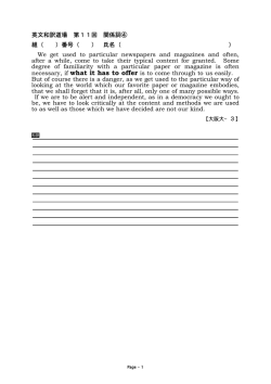
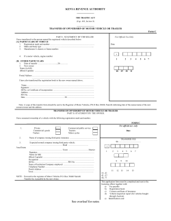
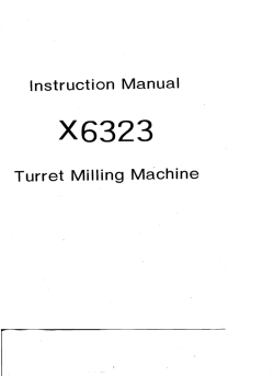
MAGAZINE & HOPPER-FED PAINTBALL RIFLE TIBERIUS ARMS TECHNICAL MANUAL TECHNICAL MANUAL MAGAZINE & HOPPER-FED .68 CAL PAINTBALL RIFLE PATENTS PENDING TABLE OF CONTENTS WARNING: This is not a toy. Misuse may cause serious injury or death. Eye protection designed specifically for paintball must be worn by the user and persons within range. Recommend 18 years or older to purchase. Persons under 18 must have adult supervision. READ OWNER'S MANUAL BEFORE USING. Warnings...................................................................................................................................................................................................................1 T15 Rifle Diagram..................................................................................................................................................................................................2 Operational Instructions.....................................................................................................................................................................................3 Magazine Instructions.........................................................................................................................................................................................4 Velocity Instructions.............................................................................................................................................................................................6 WARNING/LIABILITY STATEMENT This marker is not a toy and is surrendered by Tiberius Arms, Inc., with the understanding that the purchaser assumes all liability from unsafe handling or any action that constitutes a violation of any applicable laws or regulations. Tiberius Arms, Inc. shall not be liable for personal injury, loss of property or life resulting from the use of this product under any circumstances, including any intentional, reckless, negligent or accidental discharges. Hopper Adapter.....................................................................................................................................................................................................7 All information contained in this manual is subject to change without notice. Tiberius Arms, Inc., reserves the right to make changes and improvements to products without incurring any obligation to incorporate such improvements in products previously sold. Warranty and Repairs...........................................................................................................................................................................................9 If you, as a user, do not accept liability, Tiberius Arms, Inc., requests that you do not use a Tiberius Arms marker. By using this Tiberius Arms marker you release Tiberius Arms, Inc., of any and all liability associated with its use. Assembly Guide ..................................................................................................................................................................................................10 Lower Receiver Assembly ................................................................................................................................................................................11 Upper Receiver Assembly ...............................................................................................................................................................................12 Elbow Assembly ..................................................................................................................................................................................................13 Trigger Group Assembly ..................................................................................................................................................................................14 WARNINGS Treat every marker as if loaded. Never look down barrel of a paintball marker. Keep finger off trigger until ready to shoot. Never point marker at anything you do not wish to shoot. Keep barrel blocking device in or on marker’s muzzle when not shooting. Always remove paintballs and propellant source before disassembling. After removing propellant source, point marker in safe direction and discharge until marker is degassed. Store marker unloaded and degassed in secure place. Follow warnings listed on propellant source for handling and storage. Do not shoot at fragile objects such as windows. Every person within range must wear eye, face and ear protection designed specifically to stop paintballs. Ensure the top face of the sear and outer rim of the firing bolt are free of oil, grease, or contaminants. Tiberius Arms marker you release Tiberius Arms, Inc., of any and all liability associated with its use. Barrel Assembly...................................................................................................................................................................................................15 CONGRATULATIONS Firing Bolt Assembly...........................................................................................................................................................................................16 Congratulations on your purchase of the T15 Tiberius Arms Marker! Manifold and Air Chamber Assembly..........................................................................................................................................................17 This marker has been designed by Tiberius Arms with reliability, accuracy and durability in mind. When properly handled, the T15 will give many years of dependable service. Magazine Assembly............................................................................................................................................................................................18 Please take the time to read through this manual and become familiar with the parts, operation, maintenance, and safety precautions before you attempt to load or fire this marker. Troubleshooting..................................................................................................................................................................................................19 By purchasing this marker, you assume total responsibility for its safe and lawful use. You must observe the same safety precautions as you would with any firearm to assure the safety of not only yourself but everyone around you. The operator should use caution at all times when maintaining and firing this marker. Do not load or fire this marker until you have completely read this manual and are familiar with its mechanical operation and handling characteristics before use. T15 MANUAL 1 T15 RIFLE DIAGRAM T15 MAGAZINE DIAGRAM PROJECTILE RETAINER PIN STOCK PAINTBALL VIEWPORT CHARGING HANDLE BARREL MAGAZINE WINDER TRIGGER MAGAZINE MODEL SPECIFICATIONS 2 Caliber: .68 Height: 7" Action: Semi-auto Barrel Length: 12 ½" Power: HPA/Co2 Weight: 5.8lbs Length: 30" Magazine cap: 19rd T15 MANUAL T15 MANUAL 3 T15 OPERATIONAL INSTRUCTIONS GETTING STARTED Read this entire manual before using this marker. Keep your marker pointed in a safe direction at all times. 1. 2. 3. SAFETY - Place the T15 in safe position by moving the safety selector switch to the no fire position. The safety is located just above the grip. UNLOADING MAGAZINE - Ensure that there are no projectiles in your marker by grabbing the magazine, pressing the magazine release, and pulling the magazine free from the T15. LOADING & CHARGING THE MAGAZINE 1. LOAD PAINT - Place 19 First Strike® or 19 round .68 caliber paintballs into the magazine from the top. The projectiles will be held in place automatically by the projectile retainer tab. You can lock the ball pusher down by winding the crank until it stops. 2.LOAD MAGAZINE - Place the magazine in the magazine well of the T15 marker with the projectiles closest to the end of the barrel. Once the magazine has started into magazine well seat it completely until it has been secured by the magazine release. If the magazine does not seat completely, pull it out of the magazine well and allow any balls that may have ejected from the magazine to fall out of the magazine well before reloading. DETAIL A SCALE 1 : 1 REMOVING THE BARREL - Ensure that there are no projectiles remaining in the marker by removing the magazine and looking through the magazine well into the breach. Remove the barrel by grabbing it at the end between the muzzle brake and the gas block and rotate it counter clockwise until it comes free. DO NOT try to remove the barrel by rotating the hand guard or gas block. This will cause damage to your marker. 4 T15 MANUAL T15 MANUAL 5 FIRING THE T15 1. If the air source to the marker has been engaged and the magazine has been inserted into the gun, then the T15 is now ready to fire. Point the T15 in a safe direction, rotate the safety so it is in firing mode, and pull the trigger. HOPPER ATTACHMENT NOTE - extra magazines can be carried for quick reloads in the field. 1. REMOVE HOPPER COVER PLATE Take the hand guard off of the marker and use the barrel nut tool to remove the barrel sleeve. Once the barrel sleeve is removed, push the load door retaining pin out towards the front of the marker. 2. ATTACH HOPPER ELBOW - Seat the hopper adapter against the marker and push the load door retaining pin towards the back of the marker so it holds the hopper elbow in place. 3. ROTATE BARREL - With the magazine removed rotate the barrel by grabbing it at the end between the muzzle brake and the gas block. Look into the magazine well to confirm the position of the ball port in the barrel. UNLOADING THE T15 1. Place T15 in the safe mode and point in a safe direction. If all projectiles have been fired, grab the magazine and press magazine release with other hand. Catch magazine so it does not fall on ground. Visually inspect the magazine well to ensure all projectiles are clear from the T15. Visually inspect the projectile view port to ensure all projectiles are clear. 2. If all projectiles have not been fired, follow above procedures but ensure that you turn the T15 on its side while removing the magazine. The projectile that is in the chamber will be free and can fall on the ground if the T15 is kept in a horizontal position. Place your hand under the magazine well and capture the loose projectile as you turn the T15 vertically. 3. Your T15 should now be free of any projectiles. Verify the T15 is on safe and store in a safe and secure location. SET VELOCITY 1. Insert a 3/32" Allen Wrench as depicted. 2. To increase velocity, turn counter clockwise. To decrease velocity turn clockwise. 3. Fire once to clear chamber after each adjustment,then measure velocity of the second shot. SAFETY TIP: Always measure marker’s velocity before playing paintball. Never shoot at velocities in excess of 300 ft/s (91 .44 mls). Recommended velocity is 270 ft/s. DO NOT try to rotate the barrel by rotating the hand guard or gas block. This will cause damage to your marker. 6 T15 MANUAL T15 MANUAL 7 T15 CLEANING & MAINTENANCE WARRANTY AND REPAIRS CLEANING Tiberius Arms Inc is dedicated to providing you with the quality support necessary for the utmost satisfaction of that technology. Tiberius Arms products are crafted with the finest materials and designed for trouble-free performance. We warrant that this marker is found free from defects in materials and workmanship for a period of 1 year from the original date of purchase. Unauthorized modifications alterations, neglect, or abuse of this product voids any warranty. The warranty covers the parts and labor required to repair the product to proper working order. To register your marker for warranty please register online at www.tiberiusarms.com Never perform maintenance on a loaded or pressurized T15 marker. Remove all projectiles from the magazine and marker prior to doing any cleaning or maintenance. Never use petroleum based cleaning solvents or lubricants. Do not use cleaning solvents that come in aerosol cans. To clean the T15 marker, remove the barrel as described in the “Operational Instructions”. Use a .68 caliber soft nylon brush or 12 gauge patch tip with a soft cotton cloth to clean the barrel. Do not place lubricant or water in the barrel of the T15. It is designed to be used with the barrel completely dry. Keep the barrel of the T15 dry. Wipe off any dirt or grime from the outside of the T15 with a dry cloth. In the event warranty or other non-warranty related repairs are required, send the product(s) to Tiberius Arms Inc. We strive to complete the necessary repair work within a reasonable amount of time and return it to you via the best shipping method. On claims submitted as outlined, Tiberius Arms Inc. will repair or replace, free of charge, any of its markers that have failed through defect in material or workmanship. For assistance with warranty and repair, call 260-478-2500. For warranty and non-warranty repair, ship the product(s) to Tiberius Arms Inc. with postage or delivery charges prepaid. Include a brief statement regarding the requested repair, point of contact, return address, and telephone number where the point of contact may be reached during normal business hours. Ship to: Tiberius Arms Inc. ATTN: Warranty 2717 Ferguson Road Ft. Wayne, IN. 46809 To clean the magazine, wind the ball pusher all the way back. The magazine is designed with a spring retention sleeve that will keep the spring from binding when the the magazine is taken apart. OILING THE MARKER IMPORTANT: Before performing any of the following instructions, remove magazine. Point marker in safe direction and discharge until degassed. Note: Always remove the air source or degas the marker while not in use. This marker was packaged with an ASA on/off to degas the marker without removing the air source. For optimum performance, do the following monthly: Place 2 drops of NON-PETROLEUM BASED synthetic paintball marker oil into the ASA of the marker before attaching an air source. When the marker gases up the air will blow the oil through out the internals of the marker. OPERATIONAL CONSIDERATIONS The operational temperature range for the T15 marker is 37° F to 120°F. The T15 is designed to operate on a minimum of 725psi of air pressure. If using Co2 in warm weather, you may need to adjust the re-cock adjustment (part number 16, page 17). 8 T15 MANUAL T15 MANUAL 9 A 1 sem 1 B 1 A 1 T15 ASSEMBLY GUIDE 1 ITEM NO. 1 NAME 1 Lower Receiver 2 Bolt Delta Ring Assembly 3 Air Manifold 4 Upper Receiver 5 Upper Manifold 6 Lower Manifold B D S C 03 1 1 1 1 3 ITEM NO. 7 8 9 10 11 LOWER RECEIVER ASSEMBLY ITEM NO. NAME Barrel Delta Ring Barrel Sleeve Trigger Group Cross Pins 7 PART NUMBER NAME PART NUMBER NAME AR11A002 AR11A003 AR11A101 AR11A102 AR11A103 AR11A104 AR11A105 AR11A106 AR11A107 AR11A111 Magazine Release Bar Assy Grip Front Stip Pin Rear Strip Pin Mag Release Button Selector Index Pin Rear Air Plug Rear ASA Trigger Guard Selector 15 ORNG 012-P90 Rear ASA O-ring 16 AR11A501 Selector Index Spring 18 AR11A503 Trigger Guard Spring 19 AR11A505 Magazine Release Bar Spring 20 ORNG 006-B70 Rear Air Plug Screw O-ring 21 H-F 1032 3/4 Rear ASA Screws (2) 22 H-SSS 440 1/8 Rear Strip Pin Set Screw 23 H-B 832 5/8 Rear Air Plug Screw 24 H-S 1/4-20 5/8 Grip Screw Without ASA 25 AR11A902 Trigger Guard Spring Pin 11 AR11A201 Rear Plate 26 H-D .045 1/4 Trigger Guard Cross Pin 12 AR11A901 Strip Pin Stop Pin 27 AR11A905 Bold Release Lever Pin 13 AR11A108 Trigger Guard Straight Pin 28 AR11A004 Bolt Release Lever 14 AR11A109 Lower Air Plug 29 AR11A001 Lower Receiver 30 ORNG 010-B70 Rear ASA O-ring 31 ORNG 008-B70 Lower Air Plug O-ring 32 WHR 1/4 9 4 ITEM NO. 1 2 3 4 5 6 7 8 9 10 Lock Washer 8 5 6 2 10 3 1 11 NOTE: To remove the delta ring and barrel sleeve, you must use the barrel nut tool. DO NOT try to remove the delta ring and barrel sleeve by rotating the hand guard or gas block. This will cause damage to your marker 10 T15 MANUAL T15 MANUAL 11 UPPER RECEIVER ASSEMBLY ITEM NO. 1 2 3 4 5 6 7 8 9 10 PART NUMBER NAME AR12A002 AR12A102 H-F 1032 9/16 AR12A101 AR12A202 AR12A201 Charging Handle Sleeve Sleeve Mounting Screw Forward Assist Button Charging Handle Catch Dust Cover Barrel Index Ball Forward Assist Spring Ejector Door Spring Charging Handle Catch Spring H-BALL 1/4-CHROM AR12A501 AR12A502 AR12A503 ITEM NO. 11 12 13 14 15 16 17 18 19 20 ELBOW ASSEMBLY ITEM NO. PART NUMBER NAME AR12A504 AR12A701 AR12A801 AR12A802 H-D 1/8 3.875 H-D 3/32 .45 H-D .078 1/4-SS Barrel Index Ball Spring Dust Cover Pin Retainer Detent Plug Screw Detent Adjust Screw Dust Cover Pin Charging Handle Retaining Pin Charging Handle Catch Pin Forward Assist Pin Upper Receiver Catch Plate Pin H-D 3/32 .680-SS AR12A001 H-D 1/8 5/8 1 2 3 4 5 PART NUMBER NAME H-BALL 3.5MM AR12E001 AR12E201 T-S 832 5/8 16 5 6 7 PART NUMBER 1 AR12E301 2 AR12E001 1 Elbow Door AR12A002 Charging Handle 1 1 3 AR12E201 91185A446 2 Catch Plate AR12A102 Sleeve 1 1 4 5 91255A189 3 AR12A803 Sleeve Screw 1 AR12A101Spring Forward Assist Button 1 Charging Handle Catch 1 6 AR12E501 7 96537A140 DESCRIPTION Clamping Thumb Screw Catch Plate Screw 4 Clamp Nut AR12A202 6 AR12A203 Dust Cover 1 7 AR12A301 Barrel Index Ball 1 8 AR12A501 Forward Assist Spring 1 9 AR12A502 Ejector Door Spring 1 AR12A503 Charging Handle Catch Spring 1 11 AR12A504 Index Ball Spring 1 12 AR12A701 Dust Cover Pin Retainer 1 13 AR12A801 Detent Plug Screw 1 14 AR12A802 Detent Adjust Screw 1 15 AR12A903 Dust Cover Pin 1 AR12A904 Charging Handle Retaining Pin 1 AR12A905 Charging Handle Catch Pin 1 18 AR12A906 Forward Assist Pin 1 19 AR12A001 Upper Recever 1 20 AR12A907 Catch Plate Pin 1 10 19 6 14 13 11 4 7 16 2 17 4 3 5 Catch Plate Screw Spring Clamp Nut QTY.1 5 1 NAME QTY. ITEM NO. PART NUMBER 3.5mm StainlessDESCRIPTION Ball 18 1 PART NUMBER AR12E801 AR12E501 H-NUT 832 U ITEM NO. 17 10 ITEM NO. Catch Plate Ball Elbow Door Catch Plate Clamp Screw 1 1 1 1 7 2 8 9 6 20 3 12 15 12 T15 MANUAL T15 MANUAL 13 TRIGGER GROUP ASSEMBLY ITEM NO. 1 2 3 4 5 6 7 8 9 10 PART NUMBER AR11C001 AR11C101 AR11C201 AR11C202 AR11C501 AR11C502 AR11C503 H-D 1/8 .688 H-D .78 .550 H-D .078 1/4-SS BARREL ASSEMBLY ITEM NO. NAME 1 2 3 4 5 6 7 Trigger Trigger Housing Trigger Pawl Sear Trigger Spring Sear Spring Pawl Spring Sear/Trigger Pin Sear Spring Pin Pawl Pin PART NUMBER NAME ITEM NO. 81-2305.35 Barrel Nubbins (2) AR12F105 Barrel ORNG 020-B70 Barrel Shake O-ring ORNG 1.5X17-B70 Barrel Brake O-ring MR-2381 Muzzle Brake AR12F103 Barrel Sleeve AR12F104 Gas Block PART NUMBER NAME 8 AR12F201 Front Cap ITEM NO. PART NUMBER DESCRIPTION 9 AR12F202 Sleeve Key 1 AR11C001 Trigger 10 AR12F501 Sleeve Retainer Ring 2 AR11C101 Trigger Housing 11 AR12F102 Delta Ring AR11C201 Barrel Nut 13 4 AR12F203 AR11C202 Barrel Nut Snap Ring 14 AR12F502 5 Delta Ring Wave Spring AR11C501 Trigger Spring 1 6 AR11C502 Sear Spring 1 7 AR11C503 Pawl Spring 1 8 AR11C901 & 903 Sear/Trigger Pin 2 9 AR11C902 Sear Spring Pin 1 10 AR11C905 Pawl Pin 1 Trigger Pawl 1 Sear 1 9 2 13 9 6 12 8 11 14 7 10 10 8 7 1 14 T15 MANUAL T15 MANUAL 1 3 AR12F101 6 3 1 12 4 5 Q 15 FIRING BOLT ASSEMBLY ITEM NO. 1 2 3 4 5 6 7 8 9 PART NUMBER AR12C101 AR12C102 AR12C103 AR12C104 AR12C105 ORNG 018-P70 ORNG 012-P70 ORNG 018-P70 H-B 1032 5/8 NAME ITEM NO. Bolt Striker Striker Front Bulkhead Top Screw Sleeve Bulkhead O-ring Bolt Shaft O-ring Striker O-ring Striker Inner Screw MANIFOLD & AIR CHAMBER ASSEMBLY PART NUMBER NAME ITEM NO. 1 AR11E101-C Valve Pin 3 AR11E103 Lower Manifold 4 AR11E105 Valve Seat 7 AR11E501 Valve Spring 8 ORNG 013-P70 ValveQTY. Seat O-ring PART NUMBER DESCRIPTION Upper Maniflod 1 9AR11F101ORNG 015-B70 Manifold Seal O-ring AR11F102 Velocity Adjustor 1 10 5/16 AdjustorLower 1Manifold Screw AR11F103 H-S 440Recocker AR11F104 AR11B103-C Retention Pin Valve Body 1 11 AR11F501 Retention Pin Spring 1 12 H-S 440 5/16 Lower 1Manifold Screw AR11F601 Upper Manifold O-ring 10 11 H-S 1032 1/4 AR12C901 Striker Top Screw Striker Timing Pin 12 AR12C902 Bulkhead Timing Pin 13 AR12C106 Bolt Tip Insert 14 WHR #10 Lock Washer 15 AR12D001 Rear Cap 16 AR12D501 Striker Spring 17 AR12D601 Striker Cushion ITEM NO. 1 2 3 4 5 6 7 PART NUMBER AR11F801 NAME Retention Set Screw ITEM NO. PART NUMBER NAME 13 14 15 16 ORNG 1.5X4-B70 AR11F101 AR11F102 AR11F103 Air Manifold O-ring Upper Manifold Velocity Adjuster Re-Cock Adjuster 17 AR11F104 Retention Pin 18 19 20 AR11F501 ORNG 017-S70 H-SSS 440 1/8 Retention Pin Spring Upper Manifold O-ring Retention Set Screw 1 1 8 9 7 12 4 15 3 11 10 19 13 16 16 17 15 17 18 14 16 T15 MANUAL T15 MANUAL 20 17 Magazine ASSEMBLY ITEM NO. 1 2 3 4 5 6 7 8 9 10 1 PART NUMBER AR11M001 AR11M002 AR11M003 AR11M004 AR11M005 AR11M006 AR11M007 AR11M008 H-D 1/8 7/16-SS AR11M102 NAME TROUBLESHOOTING ITEM NO. Magazine Right Magazine Left Ball Retainer Cog Pawl Crank Spring Block Follower Pawl Axle Spring Tube 2 3 11 12 13 14 15 16 17 18 19 20 PART NUMBER NAME AR11M401 AR11M501 AR11M502 AR11M503 AR11M504 AR11M701 H-B 832 5/8 H-B 832 1/4 H-B 440 3/8 H-D 1/16 5/8-SS 4 PAINT BREAKAGE Spring Cap Ferral Main Spring Pawl Spring Ball Retainer Spring Cable Follower Retainer Spring Outer Screws (2) Spool Screw Follower Retaining Ring Screws Ball Retainer Pin 5 If you experience more than a small number of broken paintballs, then there are 3 things to check: 1. First, be sure that the marker is free of broken paintballs and other debris. 2. Second, make sure that the barrel is locked in its correct position, and that both detents are installed so that they catch a projectile as it enters the breach. 3. Third, make sure the maker is set to a reasonable velocity (never over 300 ft. per sec.) 6 19 PART NUMBER DESCRIPTION 1 AR11M001 Magazine Right 2 AR11M002 3 AR11M003 Ball Retainer 1 1 16 A 6 3 14 B 4 11 20 18 C 9 7 5 10 13 17 D 8 7 ITEM NO. QTY. 1 1 4 AR11M004 Cog Spool 5 AR11M005 Pawl 1 6 AR11M006 Crank 1 7 AR11M007 Spring Block 1 8 AR11M008 Follower 1 9 AR11M101 Pawl Axel 1 10 AR11M102 11 AR11M401 Spring Cap Ferrral 1 12 AR11M501 Main Spring 19" 1 13 AR11M502 Pawl Spring 1 14 AR11M503 Ball Retainer Spring 1 A B 1 15 AR11M504 Cable 16" ? 1 16 AR11M701 Follower Retaining Ring 1 17 AR11M801 8-32 X 5/8 Button Head 2 18 AR11M803 8-32 X 1/4 ? 1 19 AR11M804 Follower Retaining Ring Screws 2 20 AR11M901 Ball Retainer Pin 1 C D 12 1 15 E E 8 MATERIAL F A 18 - CHANGE DATE BY -/-/- JSM T15 MANUAL UNLESS OTHERWISE SPECIFIED ALL DIMENSIONS ARE IN INCHES TOLERANCES: FRACTIONS 2 PLC. DEC. 3 PLC. DEC. 4 PLC. DEC. PART NAME SIZE DESIGN NO. SHEET Magazine Assembly - REV. 1/32 .01 .005 .0005 BREAK ALL EDGES DO NOT SCALE DRAWN DATE JSM 5/8/14 CHECKED UNLESS OTHERWISE SPECIFIED ALL SURFACES: 63 / DATE / - - PART NO. AR11M T15 MANUAL A 1 OF 1 SCALE 1:2 19 1(260).478.2500 | 2717 FERGUSON ROAD | FORT WAYNE, INDIANA 46809
© Copyright 2026 Paperzz