Instruction Manual
X6323
Turret Milling Machine
INDEX
MAIN SPECIFICATION
1
INSTALLATION
7
Handling
7
Cleaning
8
Floor plan
9
Foundation
'"
Adjustment of Head
'"
OPERATION
10
11
12
Operation of basic machine
12
Operation of Head
14
LUBRICATION
22
MAINTENANCE
24
Assembly of table lead screw
.. · .. ··
Assembly of cross lead screw· .. ·
··
· .. ·
24
· .. · .. ·
25
Disassembly and adjustment of gibs
26
Head
27
Stepless Variable Head
32
PARTS DRAWINGS AND PARTS LISTS
35
Basic machine
Assembly of longitudinal and cross lead screws
35
'"
41
Assembly of transmission
44
Assembly of Head component
50
Assembly of upper of stepless Variable transmission case
59
Assembly of lower component of stepless Variable transmission case
Centralized lubrication system
63
67
~.
ELECTRIC EQUIPMENTS
69
\
ATTACHMENTS
73
\
,
r
l
.••.••
i
,
Models and Specifications of 100 Serial
Specification
Model
Remarks
Motor
100-1527
100-1597
100-2522
100-2592
100-1529
100-1599
100-5522
I'
>-'
100-5592
2HP 3
525
1700/3400 r/min
220V
2HP 3
60Hz
525
1700/3400 r/min
220V
2HP 1
60Hz
525
220V
525
220V
525
220V
1700 r/min
60Hz
1700 r/min
60Hz
525
2HP 3
220V
2HP 1
1700 r/min
60Hz
2HP 1
2HP 3
Stepped Variable
525
220V
2HP 1
220V
1700 r/min
60Hz
1700 r/min
60Hz
525
1700 r/min
60Hz
Stepless Variable
Table
16 steps
9"X42"
16 steps
9,,'X49"
8 steps
9"X42"
8 steps
9"X49"
stepless
9"X42"
.
stepless
9"X49"
stepless
9"X42"
stepless
9"X49"
.
N
.
-
.
-
~
~.
;j
(J)
"0
CD
Q.
=!l
~I
~
-£E!:-
~
-- -~-
l:l
~
C)
~
"...
"
.0;)
(J)
"0
CD
7t
Q.
=!l
~o
24?6/0...)
/4'-" CQ2om?1t)
I
INCHES
;j
METRIC
A
B
C
MIN.
54+
22.4
6-.L
MAX.
66+
18+
D: 59+"0520mm)
or 66+"0695mm)
E:42"0070mm) or 49"0245mm)
----',--
18+
MIN.
MAX.
A
B
c
1384
1690
70
476
165
465
o
=:
III
0
;j
(J)
Metric
Inch
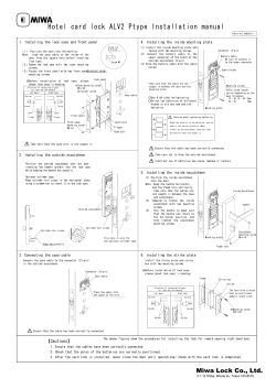
1. Main Specification
9"X49"
9"X42"
Tabl area
230X1070mm
~
(1)
Q.
s::l
230X 12450101
~
~.
::l
(J)
"'C
2. Spindle
"'C
(1)
Q.
a. Spindle hole taper
R8
R8
b. Diameter of spindle hole
5/8"
150101
c. Spindle axle movement
5"
130m01
d. Distance from spindle nose to table
2l.-"~18l.-"
70~47601m
e. Distance from vertical guideway to
6l"~18l"
165~465mm
Longitudinal
±90°
±90°
Transverse
±45°
±45°
~r
=:
4
2
spindle center line
4
2
f. Max. swivel of head in vertical
planes:
g. Range of spindle speeds: 8 steps
16 steps
stepless variable
h. Spindle power feeds
w
3. Table
78~2400 r/rnin
78~4800
r/min
70~4200 r Zmin
0.0019" ,0.0035"
0.047,0.09
0.0058"/r
0.148m01/r
o
::l
a. Max. travel
>Po
(J)
"0
~.
0'
Longitudinal (manual)
30"
35"
760mm
880mm
(Power feed fitted)
27"
32"
685mm
810mm
Transverse
12"
12"
300mm
300mm
"0
400mm
Q.
~
o0)
0)
:=:
o
::J
16"
16"
Vertical
400mm
b. No. of T-slots and slot width
3X 5/8"
3X 15. 875mm
c. Distance between T-slots
21-"
63mm
a. Max. travel
12"
300mm
b. Swivel angle
360·
360·
2
s::
~.
::J
(J)
(1)
0
::J
4. Ram
5. Motor
1. 3/1. 8Rw
a. Power(30)
1700/3400
r/min
2HP
b. Power(30)
1700
r/min
c. Power Cl Zi )
2HP
1700
r/min
6. Overall Dimensions
661.-"X592."X81"
2
8
66
l"X66 L"X81"
2
8
1690 X 1520 X 2060mm
(LxWxH)
7. Weight
2200Lb
1000kg
1690 X 1695 X 2060mm
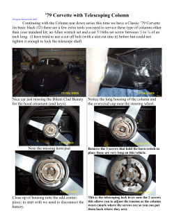
Main Specification
[
Positi"" of Matot' Unit
WItU4 s_EU~l)1MROleo'
....- ..,11:-.
-. ...
•
... .. ..... ...
.:I. ..~!·~~~
,.···:::·:f;~·
173..",
"- -- -.'.
:, -.::.~
~ .....,
..,••
_-- --_••t'
••
••
•
"llr':l
s-
So
u~"
IJ •
t
I "
......
I
~~~
~---.Q
DET AILS OF MOUNTING
AND SWIVELLNG FACE
Spindle Taper .,
R8
"'1. 3/1.8'
Motor RW
HP'"
Quill Travel··· ...
2
II ••••••••••••••••••••••••••••••••••
5"
127mm
Power Feed of Quill
° . 0019"
PeT rev. of spindle (3 rates)
1
0.0035"
0.0058"
o. 047mm
1
0.09mm
0.148mm
Stepped Variable Head
-5
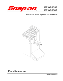
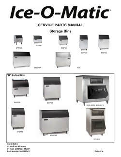
Main Specification
....--$"-1--...
2481.
P6SITI,N
.
of MOTOR UNIT •
....
- --_ .
W"' S'" SWlvlW!D IH\O 110
,~._-
...............
•
••
I
I
J- ••• - ••• ~ •
po_ • • • • • • • • • •
••
••
•.
..
..u:~======:::::;;:::;=:::::J~
. . .,.,.to::==t==::::r"t'
J.. _ ••• . ,
Stepless Variable Head
-6
Installation
WEIGHT
Basic machine
approxima tely
2200lb lOOOkg
METHOD
1
Insert eye bolt in
tapped hole. Ensure
bolt is fully secured
before lifting.
It is advisable to
swivel head before
lifting machine.
METHOD
2
Use rope sling Cshown
in the drawing rand
put soft cotton pads
between the sling and
machine edges. It is
not allowed that the
sling is directly in
touch with machine.
NOTE:
Before
lifting, tighten
ram slide lock
bolt and 4 studs
on rotary disk.
And move saddle
to column.
Handling
-7
-
Installation
1. Remove rust preventative before moving any slideways.
2. The coating is best removed by using paraffin applied
with a clean brush. When the coating has softened,
remove with clean rags.
3. Oil or grease all lubrication points. Refer to the
lubrication section of this manual. (pages 15 onwards)
4. According to the attachments list in this manual,
carefully inspect and check each attachment.
Cleaning
-8
r
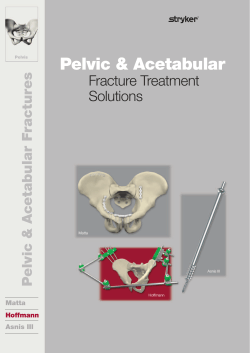
Installation
~--2"'·"""M'--"""'"
Z.OJ:t,"C.,I(tI4)
--':""""---+-+-----~---""""'t=~-1
I
I
G-+------r'
36
t---------A
TABLE SIZE 42"(l070mm)
A
59
~ "(l520mm)
49"(l245mm)
60
~ "(l695mm)
Floor Plan
-9
Installation
FOUNDATION
Ideally all milling machines
should be bolted to a concrete
foundation.
The Roundtower owever should
be placed on a solid level
floor or anti -vibration pads
to prevent any rocking
movement.
,'., .-.,."<
S"'m
Foundation
-
10
Installation
1. If the machine was delivered in a crate, the slideway handles will have been reversed.
These should be fitted as illustrated on pages 25- 26.
NOTE: If the head keeps on running in the horizontal plane swivelling 90°, pay attention to
the lubrication systems of head and transmission case.
To set a milling head square to the table two methods are available:
i. Using a large 90° setsquare mounted on the table, align faces with square..
ii. An indicator mounted in a spindle nose travelling in a 4
~ "radius.
It is important that each axis is set separately and locked.
(b)
(a)
Aligning
faces
1&RO
..... ,
.
: /;=s:.::::::.::
~
'=!:===l..
Adjustment of Head
-11
Operation
1. CLAMPING THE
SADDLEKNEE SLIDE
Moderate pressurs is suffi
cient. Excess
pressure
will
cause distortion and make the
table stiff to wind.
2. CLAMPING THE
T ABLESADDLE SLIDE
Moderate pressure is sufficient.
3. CLAMPING THE
KNEECOLUMN SLIDE
Moderate pressure is sufficient.
Operation of Basic Machine
-
12
Operating
4. SWIVEL TURRET
a. Loosen the 4 bolts with Double
Offset Ring Spanner.
b. Set the turret to the required
position.
c. Lock the 4 bolts.
5. MOVE RAM SLIDE
a. Loosen the 2 bolts with Double
Offset Ring Spanner.
b. Turn the handle to move the
slide to the desired postion.
c. Lock the slide (tighten the rear
bolt first).
NOTE: On heavy milling, the ram
shoule be kept as close to
the face of turret as possible
in order to raise the rigidity
of machine.
Operation of Basic Machine
~
13
Operation
Spindle brake
The shifting lever for
Hi-Low speed coupling
Spindle motor
Switch
power /manual feed
control handle
Power feed changing
handle
Quill dog
Manual feed operating
handwheel
..
--
manual rou gh feed
operating handle
\\
Power feed reversing
handle
Micrometer adjust
ment nut
Quill lock
Feed operating handle
......- - Dial indicator rod
Alignment reference
face
Operation of Stepped Variable Head
-14
..
~=-=--_
. .~=====:5=. .:-. .- - -~
..
Operation
1. SWIVEL BELT
HOUSING ASSEMBLY
i.
T -'- -
Slacken three Locking
Nuts 'A' . (Retain
sufficiently to stop
binding).
ii,
iii
-- -- i
. . Ii
1= z =-:.-:-:-'/=.::;;:;;iIli;;;;::::=S;;:-:..--= =:.\I
, .
l
Swivel to required
angular setting.
~---
Tighten three Locking
Nuts: before finally
securing, run spindle
to give correct spline
alignment.
.
.J
,--'
"~~-~--_-.J:.-r"
--'
-;
NOTE: Incorrect
spline
alignment can be
caused by unequal
tightening of the
locking nuts 'A'
causing
stiffness of the
quill feed which
can be felt through
manual rough feed
operating handle.
If it is not adjusted
proper ly ,noise and
shock would be
raised.
A
Brake
2. SPINDLE BRAKE
Turn and Lift lock
3. MANUAL ROUGH
FEED OPERATING
HANDLE
i.
Place the handle on
ii.
Select the most
suitable position.
iii.
Push home until the
locating pin engages.
the boss.
NOTE: It
11---- .
is suggested
that the handle should be disengaged as power feed is used or the handle
is not in use.
Operation of Head
~
.....
Operation.
4. QUILL FEED
a) FINE
i.
NEUTRAL
HAND FEED
b) AUTOMATIC FEED
Disengage power/manual position
Maximum loading 3/81/(9. Smm idia.
operating handle 'A'.
drill in steel.
11.
Locate 'C' in mid (neutral rposition.
iii.
Engage feed Operating Handle 'B'.
IV.
Now the quill is under handwheel
I.
Ensure quill lock is off '0'.
11.
Set micrometer dial to required
depth 'E'
control.
m,
Engage power/manual position operating
handle 'A' (when motor has stopped. )
iv.
Select feed rate 'F'.
v.
Select feed direction 'C'.
VI.
Engage feed trip lever 'B'.
vii. The feed will automatically trip out
at a depth within ±. 0101/(±. 25mm)
vm. Hand feed to dead stop for repeating
accuracy ±. 00l"(±. 025mm.)
NOTE: Do Not Engage Automatic Feed
over 2400r/min
Operation of Head
-16
Operation
5. SPINDLE SPEEDS (Stop motor before changing speed).
Motor nominal power: 2HP 1
2HP 3
2HP 3
0 1700r/min 220V 60Hz
0 1700r/~in 220V 60Hz
0 1700/3400r/min 220V 60Hz
65
82
164
232
+
558
708
1417
2000
+
78
98
197
278
+
DIRECT
SWITCH
BACK GEAR pas. 1
570
850
1700
2400
+
DIRECT
65
82
164
232
129
164
328
462
+
BACK GEAR SWITCH
558
708
1417
2000
1117
1417
2783
4000
78
98
197
278
155
197
394
555
670
850
1700
2400
1340
1700
3400
4800
50Hz
60Hz
50Hz
. BACK GEAR
pas.
-
DIRECT
+
BACK GEAR SWITCH
60Hz
pas.
+
DIRECT
Operation of Head
-
~--------------------_
~_._---..
17
-
Operation
6. SPINDLE SPEED RANGES
a). Change Speed Within Range
1.
Isolate machine
11.
Slacken motor lock levers 'A'
ur.
Slide motor forward
IV.
Position belt on appropriate pulleys.
v.
Slide motor to the rear to tension veebelt
vt,
Tighten 2 motor locking levers
b). Change Range
1. From direct to back gear drive:
1.
Push down lever 'B' to engage a pair
of gears.
NOTE: This action will REVERSE the
pindle rotation. Move motor switch
to reverse position to obtain original
direction of spindle rotation.
2. From back gear to direct driver:
Push uplever 'B' to disengage a pair
1.
of gears.
Rotate spindle by hand until the
u.
clutches are felt to engage.
NOTE: This action will REVERSE the spindle
rotation.
Move motor switch to reverse position to obtain original direction of
spindle rotation.
Operation of Head
-
18
Operation
Speed selector
handwheel
Spindle range
selector
L.:--_]
Spindle brake
o o
handle
"CJ
Power feed
Changing handle
<,
Quill dog
Manual rough
!
I
Manual feed
feed operating
. handle
operating
handwheel
Power feed
---
reversing
Micrometer
adjustment nut
Quill lock
handle
Feed operating
handle
Dial indicator rod
Alignment reference
face
Operation of stepless variable Head
-19
-
Operation
1.
SWIVEL STEPLESS
TRANSMISSION
-- ... --
-,
~-.. --~
I
:
,...--- --
I
'
:
-,-------- -
2. SPINDLE BRAKE
see page 15
3. MANUAL ROUGH FEED OPERATING HANDLE
4. QUILL FEED
see page 16
Operation of Step less Variable Head
-
20
"'
~_.
. '---- ----J
I
see page 15
!
J"
I
\
T-----~
I
I
I
.L
see page 15 '1'
,------,
D
_._----
L_ - - - -
:
~
~
.:
-----1'
-~_._-
~
I
Operation
5. SPINDLE SPEED(Change only
when spindle is running
a). Change Speed Within Range
1.
11.
Start spindle.
Turn handwheel 'A' to select
!J
required speed.
Change only when spindle is
running.
o
b) Change Range
1.
From direct to back gear drive:
1.
Switch 'B' to '0'.
Move lever 'C' through neutral
11.
DO NOT CHANGE SPEED WHEN
SPINDLE IS STATIONARY
to LOW.
NOTE :This action will REVERSE the
spindle rotation. Move motor
switch 'B' to reverse position
( '1' of '2') to obtain original
direction of spindle rotation.
c
2.
From back gear to direct drive:
1.
11.
Switch 'B' to '0'.
Move lever 'c' through neutral
111.
to HIGH.
Rotate spindle by hand until the
DO NOT CHANGE RANGE WHILST
clutches are felt to engage.
THE SPINDLE IS RUNNING
NOTE: This action will REVERSE the
spindle rotation. Move motor
switch 'B' to reverse position
( '1' or '2') to obtain original
direction of spindle rotation.
Lever 'C'
Q;:: -
Ii/ErH
LO'W
NEUTRAL
Operation of Stepless Variable Head
-
21
Lubrication
FREQUENCY
LUBRICATE
LUBRICANT
QUANTITY
LUB.AT
Twice Daily
Spmdle down
feed
Vactra No.2
Top-up
1
Twice Daily
Quill Bearings
Vactra No.2
Top-up
2
&.
Vactra No.2
one pump
Handle
Two screws
lubricating
pump daily
2-4 pulls
3
all ways
check level
weekly
Twice weekly·
Elevating Screw
Vactra No.2
5snots
(oiloun)
NOTE :Failure to lubricate "Quill bearings"at 2 can result in tight quills
and partial seizure of quill in housing.
Lubrication
22
4
Lubrication
2
Remove
grub screw
screw in tube &.
squeeze in required amount
FREQUENCY
LUBRICATE
LUBRICANT
QUANTITY
LUB.AT
Twice Daily
Quill
Bearinzs
Vactra 1';0. 2
5-10drops
1
Spindle Down
Feed
Twice Daily
(when feed is
in use)
Drawbar
Splines
weekly
Top-up
Vactra No.2
2
!
;;
Vactra No.2
5 drops
(move quill
clown 7,")
Failure to lubricate"Quill Bearing" at 1 can result in tight quills
and partial seizure of quill in housing.
FREQUENCY
LUBRICATE
Bull gear
shifting
mechanism
Every 6
months
LUBRICANT
Lubriplate No.
107
QUANTITY
Equivalent of
1
zteaspoonful
LUB.AT
NOTE:When
greasing work
Hi-Lo lever
Lubrication
-
23
Maintenance
BACKLASH ADJUSTMENT
1. Crank the table to the left
2. Withdraw screw 'A'
~
a turn
3. While turn handle 'C' slowly,
tighten (or loosen) screw
'B'
gradually until slight drag is
felt.
4. Finally lock screw 'A' on
to 'B'.
Assembly of table Lead Screw
-
24
-------------------------------------
- - - - - -
Maintenance
c
BACKLASH ADJUSTMENT
1. Crank the saddle to Mid position
2. Withdraw 4 screws 'D'
3. Pull the saddle forward to expose screws 'A' &. 'B'
4. Withdraw screw 'A'.
~
a turn
5. While turn handle 'C' slowly. tighten adjusting screw 'B' until slight
drag is felt.
6. Lock screw 'A' on to 'B'.
7. Finally crank the saddle to the front of the knee and replace 4 screws 'D'.
Assembly of Cross Lead Screw
- 25
Maintenance
a)
Table Saddle Ways
1. Remove all swarf from area.
Table Gib Screw
2. Turn the table gib screw
clockwise whilst moving the
table until slight drag is felt.
b)
Saddle Knee Ways
1. Remove all swarf from area.
2. Remove chip wiper guards.
3. Turn gib adjusting screw
clockwise whilst moving the
saddle until slight drag is
felt.
4. Ensure chip wiper guard is
saddle Gib Adjusting
assembled properly.
Screw
c)
Knee Column Ways
1. Remove all swarf from area.
Chip wiper Guards
2. Remove chip wiper guard.
3. Turn gib adjusting screw
clockwise whilst moving knee
until slight drag is elt.
4. Ensure chip wiper guard is
assembled properly.
~~ChiP Wiper Guards
\,
Disassembly and
Adjustment of Gibs
-
-
26
-
Maintenance
VEE AND TIMING BELT
REPLACEMENT
1- Isolate machine.
2. Remove drawbar and shaft
bracket etc. from upper
cover 'A'
B
3. Remove 4 locating screws
'B' and a taper pin 'C'
\.
cr
from transmission case
upper cover.
4. Remove motor locking
~B
\
A
lever 'D' and 3 locating
nuts 'E', and loosen V - belt.
5. Swivel upper cover 'A'
about 20 ccw , then
D
take off 'A'.
6. Lift motor slightly, and
replace the belt with a new
one now.
BRAKE SHOE
REPLACEMENT
Repeat sequence 1 to 5 above
1. Remove pin 'A'.
2. Push off shaft bracket 'C'.
3. Remove 3 screws 'B'.
4. Replace shoe with a new one.
5. Tighten 3 screws 'B'.
Head
~
27
Maintenance
BALANCE SPRING REPLACEMENT
1. With quill at top of movement apply
quill lock.
2. Remove screw 'A', hub 'B', and key
'C' .
3. Remove screws 'D', allowing housing
to rotate slowly releasing spring
tension.
4. Lift end of spring from peg on the
E.
pinion shaft.
5. Take off sleeve 'E' from head
housing.
6. Remove spring from housing and
replace.
1~Turns
7. Refit spring to main housing casing
turning housing clockwise until spring
locates on peg in pinion shaft
FEED OPERATING HANDLE
ADIUSTMENT
This mechanism has been adjusted
in manufacturer. If it is requird to
be readjusted please observe the
e
procedure as follows:
1. Loosen locknut. 'A'.
2. Engage Feed Operating Handle 'C'.
3. Adjust micro nuts against quill stop .
'B' .
4. Turn adjusting screw 'D' slowly
until Handle 'C' is disengaged.
5. Secure locknut 'A' atthis point.
6. Check that smart trip action is
obtained
D---
Head
-
28
Maintenance'
COLLET ALIGNING
SCREW REPLACEMENT
1. Use felt pen, mark
reference line on quill
and nose cap 'B'.
2. Remove set screw 'A'
3. Unscrew nose cap 'B'
4. Remove lock screw 'C'
and collet aligning
screw 'D'
5. Replace 'D'; insert R. 8
collet and check that
~c
__ya
~
the dog on the end of
the screw does not foul
on the bottom of the
guide slot
6. Replace lock screw 'C'
7. Replace nose cap
~B';
check felt pen markings
for correct alignment
8. Replace set screw 'A' .
Caution do not
overtighten as this will
cause distortion
9. Check gap 'E'.
<0. 02"=0. Smm )
D
Head
-
-
29
Maintenance
QUILL REMOVAL
1. Isolate machine
2. Remove motor
3. Remove drawbar
4. Fully extend quill
5. Remove 3 nuts 'A'
6. Remove top section
complete
7. Remove 2 screws
'B' from top of
quill
8. Remove clock
spring housing 'C'
see instruction on
replacing spring
page 28.
--:::z:m.----
Head
-
30
A
Maintenance
9. Remove screw
'D' and ball
reverse lever
'E' .
10. Remove circlip
'F' .screw 'G'
and arm 'H'
11. Thread shaft
'J' through mi
o
cro nuts and
remove.
12. Remove screw
r~--- K
'K' and stop
'L'
13. Remove quill.
14. Clean all areas,
oil liberally and
reassemble.
15. Check correct
operation of fe
ed operating
handle (see the
details on page
28).
Re-assembley
of spline align
ment See page
F
15.
H
Head
r---------:.....-----
-
31
-
Maintenance
MOTOR REMOVAL
1. Isolate machine.
2. Remove 3 screws 'A'
&. cover 'B'.
3. Rotate the speed changer to the highest
UIB----it--- D
speed.
4. Remove the reversing switch from the
belt housing.
5. Remove the two locking nuts 'D'.
6. Remove screw 'C'.
7. Ease the lower drive disc and remove
the motor.
ll~---(.,
Stepless Variable Head
-
32
Maintenance
DRIVE BELT REPLACEMENT
,
1. Remove the motor as descr
ibed on page 32.
2. Remove the three screws
'A' ;insert into the adjacent
tapped holes and withdraw
bearing housing 'B'.
3. Remove the screws and the
bushes 'C'.
4. Remove four screws 'D' and
G
one screw 'E'.
5. Remove four screws securing
the speed changer 'F'.
6. Remove top housing 'G' i tap
to clear the dowels.
7. Replace the belt.
TIMING BELT
REPLACEMENT
1. Remove the motor.
2. Lower the quill to full
extent.
3. Remove the two lower cap
screws 'A' from the speed
changer housing.
4. Remove the four cap screws
'B' .
5. Remove the top assemblv
'C' and tap to clear dowels.
6. Replace the belt.
i
A
mr===rJe:.-,
Stepless Variable Head
-
33
Maintenance
BRAKE SHOE REPLACEMFNT
1. Remove the top section.
I
2. Remove the two screws 'A'.
3. Remove the clutch hub assembly
'B' .
4. Remove the bearing drive discs and
circlips from the hub assembly
'B'
5. Replace the brake shoes 'C'.
6. Thread the hub 'B' through the
bearing and reassemble the discs etc.
NOTE: when brake shoe bas been replaced, ensure spindle brake is
secured.
Step less Variable Head
-
34
Basic. Machine·
-
35
Basic Machine
TEM
NO.
SPECIFICATION QTY.
DESCRIPTION
PART NO.
1
GB11B-76
Tapered Pin
2
GB70-76
Socket HD Cap Screw
\
BX50
1
MI0X35
3
..
1
3
X6325-1015
Worm Gear
4
X6325-1016
Ram Adapter
5
X6325-1111
Nameplate
1
X6325-1122
Nameplate
1
6
X6325-1110
Worm
1
7
X6325-101B
Flange
1
B
GB70-76
Socket Head Cap Screw
9
X6325-1109
Retaining Ring
10
GB71-76
Tapered Set Screw
11
X6325-1012
Rain
1
12
X6325-1014
Turret
1
13
GB70-76
Socket HD Cap Screw
MBX20,
B
14
GB11B-76
Tapered
8X30
2
15
X6325-1112
Nameplate
16
GB827-76
Rivet
,
".
17
X6325-1107
Shaft
18
X6325·-1108A
Bolt
GBI096-79
19
..
1
M6X16
3
1
M5XI0
1
1
2X5
.
12
,
1
.
•• J"
Flat K~y
"
'
.
5X12
3
1
,
-
20
X6325-1124
Clamping Sleeve
1
30.
X6323-6011
Table
1
X6323-6011-2
Table
1
31
GB37-76,
Bolt for T ~ Slot
32
X6323-6108
Positive Stop
33
GB55-76
ThickvHex. Nut
34
X6325-61Bl
Plugger
36
M:BX 35
2
2
MB
2
'1
--
Basic Machine
ITEM
NO.
PART NO.
DESCRIPTION
SPECIFICATION
QTY.
35
X6325-6104A
Clamping Plate
1
36
X6325-6182
Screw
1
37
X6325-4111
Handle
1
]B1341-73
Handle Holder
M8x25
1
38
GB79-76
Set Screw
M6x8
1
39
X6325-6183
Screw
40
GB70-76
Socket HD Cap Screw
41
X6325-6106
Gib Screw
2
42
X6323-6013
Table Stop Bracket
1
43
X6323-6019
Gib
1
44
X6325-6109
Wiper
4
45
X6325-6159
Pin
2
46
5105-1104
Locking Pin
1
X6325-4302
Locking Pin
1
47
X6323-6107
Locking Screw
2
48
X6323-6109
Locking Lever
2
49
X6323-6016
Gib
1
50
X6325-6105
Wiper Holder
4
51
GB67-76
Screw
52
X6323-6012
Saddle
1
53
X3625-4113
Wiper Holder
1
54
X6325-4201
Wiper
2
55
X6325-4018A
Bevel Gib
1
X6325-4112
Gib Screw
1
56
GB67-76
Screw
57
X6325-4114
Wiper Holder
1
59
X6323-6104
Chip Guard
1
1
M8x16
2
M5x8
8
M6x12
2
-
37
Basic Machine
ITEM
DESCRIPTION
PART
NO.
,
NO.
SPECIFICATION
QTY.
60
X6323-6103
Chip Guard
1
61
X6323-6102
Chip Guard
1
62
X6323-6014
Gib
4
63
X6323-6015
Clamping Plate
4
64
GB52-76
Hex. Nut
M6
8
65
GB85-76
Set Screw
M6x20
8
66
GB70-76
Socket HD Cap Screw
M8x14
2
67
X6325-4011A
Knee
1
70
X6325-4302
Lock Pin
1
71
X6325-4110
Screw
1
72
GB79-76
Set Screw
73
X6325-4111
Lever
"4
JB1341-73
Lever Holder
M8x25
1
75
GB52-76
Hex. Nut
M12
2
76
GBI096-79
Flat Key
5x20
1
77
GB93-76
Spring Washer
12
2
GB97-76
Washer
12
2
78
X6325-4102
Sprial Bevel Gear
1
79
X6325-4013
Washer
1
80
X6325-4103
Elevating Screw
1
81
X6325-4101
Bearing Bush
1
82
206
Single Row Radial Ball
M6x8
1
1
..
30x62x 16
1
Bearing
-
83
X6325-4012
Bearing Retainer Ring
84
GB70-76
Socket HD Cap Screw
M8x14
3
85
GB78-76
Set Screw
M6x8
1
86
X6325-4125
Lever
38
1
1
Basic Machine
ITEM
NO.
DESCRIPTION
PART NO.
SPECIFICATION
QTY.
GB97-76
Washer
4
1
JB1335-73-2
Handle
M12x90
1
M12x90
1
JB1335-73-3
_Elastic Ring
87
X6325-4017A
Holder
1
88
X6325-4115
Clutch
1
89
X6325-4109
Clutch
1
90
X6325-4108
Nut
1
91
X6325-4106-2
Dial
1
92
X6325-4107
Sleeve
1
93
GB893-76
Snap Ring
94
X6325-4016
Requlating Ring
95
204
Single Row Radial Ball
47
1
1
20x47x 14
1
M6x16
3
Bearing
96
GB70-76
Socket HD Cap Screw
97
X6325-4015
Bearing Cap
98
GB1096-79
Flat Pin
·99
X6325-4105
Shaft
100
204
Single Row Radial Ball
1
s« 16
2
1
20x47x14
1
Bearing
101
X6325-4014
Washer
1
102
X6325-4104
Spiral Bevel Gear
1
103
GB70-76
Socket HD Cap Screw
104
S105-4012
Bracket
1
105
J325-4301
Nut
1
106
GB1152-76
Oil Cup
M6
1
107
GB70-76
Socket HD Cap Screw
M8x14
3
108
S105-1011
Column
M10x25
2
1
-
39
-
Basic Machine
ITEM
NO.
DESCRIPTION
PART NO.
SPECIFICATION
QTY.
117
X6325-1127
Nameplate
1
118
S105-1014
Spider
1
119
X6325-1103A
Bolt
2
120
X6325-1105
Gear Shaft
1
121
X6325-1106
Lever Rod
2
122
]B1341-73
Plastic Lever Holder
Ml0X 32
2
123
GB97-96
Washer
12
4
124
X6325-1013
Rotary Disk
1
125
X6325-1102
Key
2
GB119-76
Roll Pin
126
X6325-1104
Clamping Block
2
127
X6325-1101
Clamping Block
2
128
GB91-76
Split Pin
3x50
2
129
GB898-76
Stud
AM12X 110
4
GB923-76
Nut
M12
4
GB79-76
Set Screw
M8X16
1
130
-
40
3ga X 12
4
AssemblY of Longitudinal and Cross Lead Screws'
-
41
Assembly of Longitudinal and Cross Lead Screws
ITEM
.
NO.
1
2
PART NO.
GB923-76
DESCRIPTION
Ball Type Nut
SPECIFICATION
QTY.
M12 .
2
M16
1
3
X6325-4125
Handle
1B1335-73-2
Handle Rod
M12x90
3
1B1335-73-3
Elastic Ring
M12x90
3
GB97-76
Washer'
4
3
3
X6325-6156B
Handle Body
1
4
X6325-6158
Nut
1
5
X6325-6157
Dial
1
6
X6325-6110
Sleeve
1
7
GB70-76
Socket HD Cap Screw
8
9
. X6325C-6013 .
36204
.
M8x16
Flange
Single Row Radial Thrust
7
1
20x47x14
4
Ball Bearing
10
X6325-6111
Adjusting Spacer
2
11
X6325-6112
Adjusting Spacer
3
12
GB70-76
Socket HD Cap Screw
13
X6325-6017
Left Bracket
14
GBI096-79
Flat Key
15
X6323-6101/1 (9" X42")
Lead Screw
1
MI0x20
8
1
4x32
1
X6323-6101-2/1 (9"X49")
-
16
X6325-6155
Regulating Screw
6
17
X6325-7334A-2
Nut
1
18
X6325-7341 ~2
Nut
1
19
GBI096-79
Flat Key
5x30
2
20
GB118-76
Female Thread Conical Pin
8x30
2
21
GB78-76
Set Screw
M8x12
2
22
X6325-6020
Nut
42
1
Assembly of Longitudinal and Cross Lead Screws
ITEM
DESCRIPTION
PART NO.
NO.
SPECIFICATION
QTY
23
X6325C-7101
Lead Screw
1
24
X6320-4124
Key
2
25
GB65-76
Screw
26
X6325C-7011
Bearing 'Bracket
27
GB70-76
Socket I-ID Cap Screw
28
X6320-4122
Bearing Sleeve
1
29
X6320-4121
Sleeve
1
30
X6325C- 7012
Bearing Retainer Ring
1
31
GB70-76
Socket I-ID Cap Screw
32
X6325C-6102
Dial
1
33
XF6325-7131
Nut
2
34
X6325A-6604
Handle Body
2
35
X6323-6018
Right Bracket
1
36
204
Single Row Radial Ball
M4x8
1
1
xno« 16
4
M8x14
3
20 x47x 14
1
Bearing
37
X6323-6105
Adjusting Pad
1
38
X6323-6106
Sleeve
1
39
X6323-4120-2A
Dial
1
40
X6323-6301-2
Nut
1
41
X6323-6302-2
Nut
1
-
43
Assembly of Transmission
7J~~18
lJ~~ 71
7'-8'> 0
,.~
7s-Gt.
-
44
Assembly of Transmission
ITEM
NO.
SPECIFICATION
DESCRIPTION
PART NO.
QTY.
1
X6325-90107B
Drawbar
1
2
X6325-90110
Drawbar Washer
1
GB1235-76
16X2
. O-Seal Ring
3
X6325-2106
Nut
4
X6325-2105
Nut
5
D36107
Single Row Radial Thrust
1
1
35x62X14
1
1
Ball Bearing
6
X6325-2011
Adjustable Spacer
7
X6325-2012
Adjustable Spacer
8
D36107
Single Row Radial Thrust
1
35X62X14
1
1
Ball Bearing
9
X6325-2109
Spring
4
11
X6325-2108
Bearing Bracket
1
14
X6325-2138D
Screw
2
X6325-2126
Screw
1
15
X6325-2128
External Spring
2
16
GB119-76
Roll Pin
17
X6325-2103
Brake Lock Stud
1
18
X6325-2203
Brake Block
1
19
X6325-2303B-2
Pulley
1
20
X6325-2107D
Coupling Shaft
2. 5ga X 16
4
1
8x25
J
21
GB1096-79
Flat Key
22
GBl171-74
V-Rubber Belt
1
23
2J650
Timing Belt
1
24
X6325-2307D
Pulley Flange
2
25
X6325-2306D
Timing Belt Pulley
1
26
GB858-76
Thrust Washer for
1
16
1
Round Nut
-
---------------------
-
- - - -
-----
45
- -
--
..
Assembly of Transmission
ITEM
PART NO.
NO.
DESCRIPTION
SPECIFICATION
QTY.
27
GB68-76
Sunk Screw
M5x8
16
28
GB812-76
Round Nut
M16X 1. 5
1
29
]B1341-73
Plastic Handle Holder
M6x20
1
30
GB73-76
Set Screw
M3x5
1
31
X6325-2101
Handle Holder
1
X6325-2135
Handle
1
32
X6325-2131
Pin
1
33
X6325-2102
Sleeve
1
34
X6325-2104
Washer
1
35
X6325-2301D
Cover
1
36
GB118-76
Tapered Pin
lOx30
1
37
GB70-76
Socket HD Cap Screw
MlOx 16
4
38
X6325-2016F
Notor Cap
39
X6325-5117
Handle Rod
1
1
<,
-
40
JB1341-73
Handle Holder
M6x20
2
41
GB397-76
Stud
M12x 35
2
42
X6325-2305D
Belt Housing
1
43
X6325-2141D
Right Window Cap
1
X6325-2142D
Left Window Cap
1
X6325-2140D
Spring Plate
1
X6325-2143D
Bracket
2
GB52-76
Hex. Nut
M5
1
GB52-76
Hex. Nut
M6
1
GB70-76
Socket HD Cap Screw
M5x16
1
GB93-76
Spring Washer
5
1
GB119-76
Roll Pin
4ga X 16
2
]B1357-73
Holder
M6x20
2
46
Assembly of Transmission
ITEM
DESCRIPTION
PART NO.
NO.
SPECIFICATION
QTY.
GB96-76
Washer
12
2
GB54-76
Thick Hex. Nut
M12
2
X6325-213.7D
Thick Hex. Nut
1
45
X6325-2144D
Handle
1
46
GB79-76
Set Screw
47
X6325-2304B-2
Pulley
1
48
X6325-2110F
Washer
1
49
GB93-76
Spring Washer
8
1
50
GB30-76
Hex. Head Bolt
M18X25
1
51
GB1157-74
Cotton Core Type Oil Cap
1
52
X6325-22198A
Oil Cup Adapter
1
53
X6325-2208
Cotton Coer Tube
1
54
GB67-76
Screw
55
X6325-2201D
Cap
56
GBl096-79
Flat Key
57
X6325-2119D
Wonn Coupling Shaft
1
58
X6325-2122D
Bull Gear
1
59
GB70-76
Socket HD Cap Screw
M6x16
4
60
GB118-76
Female Thread Conical Pin
8x25
2
61
X6325-2013
Bearing Brackey
62
203
Single Row Radial Ball Bearing
17x40x 12
1
63
GB893-76
Elastic Ring for Hole
40
1
64
X6325-2116
Spline Shaft
65
GB1099-79
Woodruff Key
66
X6325-2115D
Pinion
67
203
Single Row Radial Ball Bearing
68
X6325-2117
Plug
44
M6X8
M6xl0
1
3
1
s« 16
1
1
1
s x 16
1
1
17x40x 12
1
1
-- 47
Assembly of Transmission
ITEM
'n
DESCRIPTION
PART NO.
NO.
D36108
Single Row Radial Thrust
SPECIFICATION
QTY.
40 X68X 15
2
39
1
M39x 1.5
1
Ball Bearing
73
GB858-76
Thrust Washer for Round
Nut
-
74
GB812-76
Round Nut
75
X6325-2134
Cover
76
GB70-76
Socket
77
X6325-2120
Regulating Ring
1
78
X6325-2121
Regulating Ring
1
79
X6325-2308D
Shifter Fork
1
80
GB117-76
Tapered Pin
81
X6325-2111D
Drawbar
1
85
X6325-2130
Pin
1
86
GB70-76
Socket
87
X6325-2118
Shim
1
88
X6325-2014D
Shaft Bracket
1
89
GB118-76
Tapered Pin
8x25
12
90
GB70-76
Socket
M8x16
2
91
X6325-2124
Handle
92
GB117-76
Conical Pin
93
X6325-2112D
Eccentric Block
94
GB117-76
Conical Pin
95
X6325-2113
Pin
96
GB117-76
Tapered Pin
97
X6325-2114D
Spanner Shaft
1
98
X6325-2136D
Spring
1
48
1
HI)
HI)
HI)
Cap Screw
Cap Screw
Cap Screw
M6x12
3x25
M5x8
4
1
1
1
4x32
1
1
4x25
1
1
4x25
1
.
Assembly of Transmission
ITEM
NO.
PART NO.
DESCRIPTION
99
X6325-2123D
Handle
100
JB1341-73
Handle Holder
SPECIFICATION
QTY.
1
1
M8x25
-
49
,
An'lIbl,
of He a d Compon.nt
-
50
Assembly of Head Component
ITEM
NO.
DESCRIPTION
PART NO.
SPECIFICATION
M4x8
QTY.
1
GB30-76
Hex. Head Bolt
2
GB859-76
Spring Washer
3
X6325-22189
Bevel Gear
1
4
X6325-22181
Sleeve
1
5
X6325-22312
Sleeve
1
6
GB71-76
Set Screw
7
X6325-22182
Wonn Gear Spacer
1
8
X6325-22313 .
Wonn Gear
1
9
X6325-22188
Shaft
1
10
GBI096-79
Flat Key
3x 12
1
11
GBI096-79
Flat Key
3x 16
1
12
GB52-76
Hex. Nut
M8
1
13
GB97-76
Washer
8
1
14
GBI096-79
Flat Key
3X 12
1
15
X6325-22110
Bevel Gear
1
16
X6325-22184
Feed Engage Pin
1
17
X6325-22013
Wonn Gear Support
1
18
X6325-22185
Pin
1
X6325-22186
Shaft
1
GB73-76
Set Screw
19
X6325-22314
Flange
1
20
X6325-22187
Plunger
1
21
X6325-22134
Spring
1
22
GB117-76
Tapered Pin
23
X6325-22315
Shifter Crank
24
JB1341-73
Handle Holder
M6x20
1
25
GB70-76
Socket HD Cap Screw
M5x12
3
1
1
·4
M5x8
1
M5x8
1
3x20
1
1
-
51
.....
Assembly of Head Component
ITEM
NO.
-
DESCRIPTION
PART NO.
SPECIFICATION
M6X8
QTY.
1
26
GB78-76
Set Screw
27
X6325-22306
Bush
1
28
X6325-22128
Gear
1
29
X6325-22127
Gear
1
30
X6325-22129
Gear
1
GB73-76
Set Screw
M3XlO
1
31
GBl096-79
Flat Key
3X40
1
32
GB78-76
Set Screw
M6X8
1
33
X6325-22125
Bevel Gear Shaft
34
GB894-76
Snap Ring'
35
X6325-22303
Bush
1
36
X6325-22111
Gear
1
37
GB1096-79
Flat Key
38
X6325-22130
Gear Shaft
39
GB1096-79
Flat Key
40
X6325-22192
Gear
1
41
X6325-22304
Bush
1
42
X6325-22305
Bush
1
43
X6325-22126
Wonn
1
44
X6325-22657
Screw
1
45
GB879-76
Elastic Roll Pin
46
X6325-22320
Bush.
1
47
X6325-22123
Washer
2
48
X6325-22323
Sleeve
1
49
X6325-22122
Bevel Gear
1
50
X6325-22121
Reverse Clutch
1
51
X6325-22122
Bevel Gear
1
52
~
1
14
3x20
1
1
1
3x8
3x 16
1
1
-
Assembly of Head Component
ITEM
NO.
.
DESCRIPTION
PART NO.
SPECIFICATION
QTY.
1
52
X6325-22323
Sleeve
53
GB77-76
Set Screw
M6xlO
1
54
GB78-76
Set Screw
M6x8
1
55
X6325-22117
Slide Rod
56
GB879-76
Elastic Roll Pin
57
X6325-22114
Hollow Shaft
1
60
X6325-22106
Small Shaft
1
61
GB73-76
Set Screw
62
X6325-22104
Pin
1
63
X6325-22321
Slide
1
64
X6325-22624
Eccentric Wheel
1
65
X6325-22801
Cluster Gear Cover
1
66
X6325-22183
Screw
1
67
X6325-22113
Spring
1
68
GB308-77
Steel Ball
03/16" .
1
69
GB70-76
Socket Head Cap Screw
M5x16
4
70
X6325-22625
Holden
71
GB71-76
Set Screw
M5x6
1
72
GB73-76
Set Screw
M5x6
1
73
GB70-76
Socket Head Cap Screw
M5x40
2
74
X6325-22638
Thread Pin
2
75
X6325-22805
Sleeve
1
76
GB73-76
Set Screw
M6x8
1
77
J51-9
Plug
4X2
1
78
X6325-22637
Nut
1
79
X6325-22636B
Spring
1
80
X6325-22634
Clutch
1
1
3x22
1
M5x6
1
1
-
53
I
Assembly of Head Component
ITEM
PART NO.
NO.
DESCRIPTION
SPECIFICATION
QTY.
81
X6325-22639
Coupling Shaft
1
82
X6325-22641
Key
1
83
GB67-76
Screw
M4X16
3
84
GB859-76
Spring Washer
4
3
85
GB77-76
Set Screw
M6x12
1
86
GB78-76
Set Screw
M6x12
1
87
X6325-22643
Regulating Washer
1
88
X6325-22633
Spring
1
89
X6325-22635
Top Pin
1
90
X6325-22308
Sleeve
1
91
8102
Single Row Thurst Ball
15 x28x9
1
Bearing
'. 1
92
X6325-2231O
Feed Wonn Gear
93
X6325-22642
Clutch
94
GB119-76
Roll Pin
5ga X 16
1
95
GB119-76
Roll Pin
4ga X20
1
96
X6325-22804
Connecting Rod
1
97
X6325-22640
Washer
1
98
GB894-76
Snap Ring
99
X6325-22803
Cover
100
GB77-76
Set Screw
M6x14
1
101
GB54-76
Hex. Nut
M6
1
102
GB119-76
Roll Pin
5ga X20
1
103
X6325-22622
Drawbar
1
104
X6325-22623
Handle
1
105
]B1341-73
Handle Sleeve
106
X6325-22504
Bracket
..
10
1
1
1
M8x25
1
1
0..
-
54
-
Assembly of Head Component
ITEM
NO.
DESCRIPTION
PART NO.
SPECIFICATION
QTY.
107
GB70-76
Socket Head Cap Screw
M6x14
2
108
GB77-76
Set Screw
M6x8
1
109
GBl096-79
Flat Key
4x8
1
110
X6325-22116
Feed Reverse Knob Stud
1
111
X6325-22115
Reverse Knob
1
112
X6325-22194
Pin
1
113
X6325-22627
Rataining Ring
1
114
GB308-77
Steel Ball
115
X6325-22113
Spring
1
116
X6325-22626
Set Screw
1
117
GB119-76
Roll Pin
118
X6325-22632
T-Rod
1
119
X6325-22631
Pin
1
120
Q81-1
Spring
121
X6325-22616
Shaft
1
122
X6325-22617
Sleeve
1
123
X6325-22621
Sleeve
1
124
X6325-22620
Plunger
1
125
X6325-22802
Handwheel
1
126
]B1335-73
Handle
127
X6325-22602A
Spindle
128
GB68-76
Socket HD Screw
129
X6325-22655
Lock Nut
1
130
X6325-22141A
Lock Nut
1
131
C206
Single Row Radial Ball
1
03/16"
4ga X 16
1
1.2x10x25
1
M8x65
1
1
M5x12
4
30x 62x 16
1
Bearing
132
X6325A-23664
Quill Skirt
1
-
55
-
Assembly of Head Component
ITEM
NO.
PART NO.
133
X6325-22144
134
X6325-22142
135
C46108
DESCRIPTION
I
I
SPECIFICATION
QTY.
Nose Piece
1
Spindle Dirt Shield
1
Single Row Radial Thrust
40x 68x 15
1
Ball Bearing
1
136
X6325-22139
Bearing Sleeve
1
137
X6325-22140
Bearing Sleeve
1
138
C46108
Single Row Radial Thrust
40x 68x 15
1
Ball Bearing
1
X6325-22653A
Locating Nut
1
X6325-22654
Locating Nut
1
140
GB71-76
Set Screw
141
X6325-22601
Special Set Screw
GB73-76
Set Screw
142
X6325A-23676
Quill
1
143
X6325-22201
Oil Sealer
1
144
GB52-76
Hex. Nut
M3
1
145
GB73-76
Set Screw
M3x14
1
146
X6325A-23668
Forked Rod
1
147
X6325-22619
Thread Pin
1
148
GB65-76
Screw
149
X6325-22166
Handle
1
150
X6325-22202
Retaining Plate
1
151
GB893-76
Snap Ring
152
X6325-22193
Quill Lock Bolt
1
153
X6325-22317
Lock Sleeve Tapped
1
X6325-22318
Lock Sleeve Tapped
1
X6325-22135
Special Screw
1
139
154
-
56
M5x6
1
M5x6
1
M4x8
65
2
1
Assembly of Head Component
ITEM
NO.
DESCRIPTION
PART NO.
SPECIFICATION
QTY.
1
X6325-22136
Indicator Rod
155
GB37-76
Screw for T - slot
156
X6325-22107-1
Sleeve
1
X6325-22107-2
Sleeve
3
157
X6325-22658
Nut
4
158
GB67-76
Screw
159
X6325A-23667 -2
Scale
160
GB894-76
Snap Ring
161
X6325A-23660-2
Regulating Nut
1
162
X6325A-23662-2
Dial
1
163
X6325A-23663
Stop Knob
1
164
X6325A-23661-2
Lead Screw
1
165
X6325A-23671 .
Screw
1
166
S105-22113
Shaft
1
167
GBl096-79
Flat Key
5x20
1
168
GB78-76
Set Screw
M8xlO
1
169
X6325-22155
Pin
170
GB119-76
Roll Pin
5ga X 16
1
171
GBI096-79
Flat Key
5x20
1
172
GB30-76
Hex. Bolt
M4x16
1
173
X6325A-23674
Stop Plate
1
174
X6325-22614
Set Screw
1
175
X6325-22648
Spring
1
176
GB308-77
Steel Ball
03/16"
1
177
GB71-76
Set Screw
M4x14
1
178
X6325A-23673
Handle Hub
1
179
S105-22114
Sleeve
1
4
M12x 175
M4x6
2
1
1
15
1
-
57
- - - - - - -
Assembly of Head Component
ITEM
NO.
DESCRIPTION
PART NO.
SPECIFICATION
QTY.
180
S105-22111
Sleeve
1
181
S105-22112
Spring
1
182
X6325-22153
183
X6325-22610
Lever
1
184
X6325-22609
Shaft
1
185
X6325A-23665
Screw
1
186
X6325-22179
Worm
1
187
GB1096-79
Flat Key
4X 16
1
188
GB73-76
Set Screw
M5x6
1
GB75-76
Set Screw
M5x6
1
189
X6325-22180
Shaft
1
190
X6325A-23666
Handle Rod
1
191
JB1341-73
Handle Sleeve
192
X6325A-23505
Housing
1
193
X6325-22198A
Oil Cup Adapter
1
194
GB1157-74
Oil Cup
1
195
X6325-22322
Tubing
1
i Gear
Cotton Wire
-
58
1
M8x25
1
AS,semltly of ,Upper of Steple.. Var)able Transmission Case
.........- 9
•
22·---(';;::::
U----tr--,~"'!"I'"J
"'-........:=..J~
~---85
i\-.---'·~aS
_ _ 11
-J:~~
~
-
59
-
- - - -
Assembly of Upper of Stepless Variable Transmission Case
ITEM
NO.
DESCRIPTION
PART NO.
1
GB70-76
Socket Head Cap Screw
2
XU6325-200l
Bearing Cap
4
80107
Single Row Radial Ball
SPECIFICATION
M6x16
QTY.
3
1
35x62x 14
1
Bearing
6
XU6325-2126
Socket Head Cap Screw
7
GB52-76
Hex. Nut
2
MIO
1
Motor
8
1
MI0x25
2
9
GB21-76
Hex. Screw
10
XU6325-2301
Upper Housing
1
11
XU6325-2108
Shaft
1
12
GB119-76
Roll Pin
13
XU6325-2107
Clamping Plate
1
Drawbar
1
14
4ga X25
2
15
GB91-76
Split Pin
16
XU6325-2101
Shaft
17
GB70-85
Sunk Screw
M4x20
2
18
GB93-87
Washer
4
2
22
XU6325-2002
Bearing .Sliding Housing
23
80110
Single Row Radial Ball
3x20
1
1
1
50x80x 16
1
Bearing
25
XU6325-2015
Pulley
26
GB894-76
Circlip
27
2J668
Stepless Variable Belt
1
28
XU6325-2004K
Pulley
1
29
XU6325-2010
Bearing Cap
1
30
80110
Single Row Radial Ball
Bearing
-
60
1
38
50x80x 16
1
1
p
!
!
Assembly of Upper of Step less Variable Transmission Case
ITEM
NO.
PART NO;
DESCRIPTION
SPECIFICATION
QTY.
31
XU6325-2139
Brake Spring
2
32
XU6325-2203
Brake Shoes
1
34
XU6325-2159D
Upper Coupling Shaft
1
35
XU6325-2140
Set Screw
1
38
GB1096-79
Flat Key
40
XU6325-2009D
Pulley
41
GB77-76
Socket Set Screw
43
XU6325-2014
Pulley
1
44
XU6325-2124D/1
Spring
1
45
XU6325-2125D
Spring Collar
1
46
GB70-76
Socket HD Cap Screw
M5x25
3
48
GB70-76
Socket HD Cap Screw
M8x20
1
52
GB118-76
Taper Pin
A8x30
4
53
XU6325-2307
Middle Housing
1
54
XU6325-231OD
Lower Cover
1
56
GB827-76
Rivet
58
XU6325-2313-2
Nameplate
1
61
XU6325-2312-2
Nameplate
1
63
XU6325-2308
Lower Housing
1
64
GB67-76
Screw
65
XU6325-2114
Cover Plate
66
GB894-76
Snap Ring
67
XU6325-2132
Brake Operating Finger
2
68
XU6325-2138
Shaft
1
69
]B1341-73
Handle
70
XU6325-2137
Handle Rod
8x25
1
1
M6xlO
1
Cu2x5
6
M5x6
2
1
6
1
M8x25
1
1
-
61
,
Assembly of Upper of Stepless Variable Transmission Case
ITEM
PART NO.
NO.
DESCRIPTION
SPECIFICATION
QTY.
1
71
XU6325-2136
Pin
72
GB71-76
Set Screw
73
XU6325-2134
Sleeve
1
75
XU6325-2133
Corn
1
77
GB77-76
Socket Set Screw
M6xl0
1
78
GB70-76
Socket HD Cap Screw
M6x20
1
80
GB68-76
Sunk Screw
M5x12
1
82
GB70-76
Socket HD Cap Screw
M4xlO
1
GB30-76
Hex. Bolt
MI0x30
1
Spring Washer
10
1
M5x6
1
83
XU6325-2127D
Requlating Ring
1
84
XU6325-2153K
Washer
1
85
XU6325-2161
Motor Spline Sleeve
1
86
GBI096-79
Flat Key
6x70
1
GB893-76
GBI096-79
93
-
XU6325-2205
62
Spline Sleeve
24
Assembly of Lower Componend of Stepless Variable Transmission Case
'I3,---J~.,c¥i-~---:
""'-~ \~~~,
45--~::r-r--:::
46-----4.,.~
47-----r:~~L-"I1"
.48--....!,' .......""-~
..
Assembly of Lower Component of Stepless Variable Transmission Case
ITEM
NO.
SPECIFICATION
QTY.
1
1
GB54-76
Hex. Nut
2
XU6325-2306A
60Hz Dial
4
GB79-76
Set Screw
5
XU6325-2302B
Housing
1
6
XU6325-211O
Chip Shield
1
7
GB65-76
Screws
8
XU6325-2304
Bush
9
GB119-76
Roll Pin
3ga X 25
1
Speed Changer Chain
1/8" xl-"
9
10
-
DESCRIPTION
PART NO.
M8
1
M6X12
M4x6
1
2
1
2
12
XU6325-2301
Upper Housing
1
13
XU6325-2001
Bearing Cap
1
14
XU6325-2131
Socket Head Cap Screw
2
16
XU6325-2149
Bush
1
17
XU6325-2315B
Handwheel
1
19
jB1332-73
Machine Handle
20
XU6325-2314-2
Caution Plate
21
GB78-76
Socket Set Screw
M6x8
1
25
GB70-76
Socket Head Cap Screw
M6x35
1
28.
GB117-76
Long Pin
3x 12
1
29
XU6325-2150B
Shaft
1
30
XU6325-2148
Worw
1
33
XU6325-2111
Bevel Gear
1
34
GB1096-79
Flat Key
35
XU6325-2113
Shaft
1
36
2j650
Syncro Timing Belt
1
37
XU6325-2159D
Upper Coupling Shaft
1
39
XU6325-2118K
Lower Coupling Shaft
1
64
M6x50
1
1
3x8
1
.
Assembly of Lower Component of Step less Variable Transmission Case
ITEM
NO.
DESCRIPTION
PART NO.
40
XU6325-2115B
Bull Gear
41
80108
Single Row Radial Ball
SPECIFICATION
QTY.
1
40 x68x 15
1
68
2
Bearing
42
GB893-76
Snap Ring
43
XU6325-2006
Spacer
1
44
XU6325-2308
Lower Housing
1
45
XU6325-2156
Bolt for T-slot
3
46
GB97-76
Washer
10
3
47
GB52-76
Hex. Screw
MIO
3
48
XU6325-2116
Spring Shim
1
49
XU6325-2005
Flange
1
50
GB77-76
Set Screw
51
XU6325-2311A
Guide
52
GB68-76
Socket Cap Screw
53
XU6325-2005/2
Drip Pipe
54
GB1157-74
Oil Cop
XU6325-2318
Oil Pipe Adapter
1
55
XU6325-2154
Spring
3
57
XU6325-2119B
Gear Sleeve
1
59
XU6325-2146
Gear Shaft
1
60
XU6325-2145
Detent Plate
1
61
GB52-76
Hex. Screw
M12
3
62
GB97-76
Washer
12
3
63
GB899-76
Stud
M12x80
3
64
GB77-76
Set Screw
M6x12
1
65
XU6325-2141
Set Block
1
66
XU63225-2143
Set Pin
1
M6x6
1
1
M4x8
2
1
1
1
-
p
65
Assembly of Lower Component of Stepless Variable Transmission Case
ITEM
NO.
DESCRIPTION
PART NO.
SPECIFICATION
QTY.
1
67
XU6325-2155
Spring
68
GB70-76
Socket Head Cap Screw
M5x 12
2
69
JB1341-76
Handle
M8x25
1
70
XK5032-2135
Handle Shaft
71
XU6325-2144
Handle Hub
72
GB119-76
Roll Pin
3ga X 16
2
73
GB879-76
Elestic Roll Pin
3x 16
1
74
GB70-76
Socket Head Cap Screw
M8x20
4
75
GB70-76
Socket Head Cap Screw
M5x25
3
76
XU6325-231OD
Lower Cover
77
GB1096-79
Flat Key
6x20
1
78
GB1099-79
Woodruff Key
5x 16
1
79
80203
Single Row Radial Ball
17 x40x 12
2
,
1
1
1
Bearing
-
80
XU6325-2121
Pinion Shaft
1
81
XU6325-2117
Key
1
83
XU6325-2122
Pinion
1
84
XU6325-2007
Bearing Cap
1
85
GB70-76
Socket Head Cap Screw
86
XU6325-2309
Synchro Timing Pulley
87
GB812-76
Nut
88
XU6325-2202
Front Cover
89
GB68-76
Socket Screw
66
M5X 16
2
1
M16x 1. 5
1
1
M4x20
2
Contra Iize dLubr i ca ti on System
is.
C1
--",~.,
--~~-\
•
• 1
.~
"-'
"".
u
67 -
Centralized Lubrication System
ITEM
NO.
PART NO.
SPECIFICATION
QTY.
1
GB70-76
Socket Head Cap Screw
M6x20
4
2
G20011
Sleeve
4
14
3
G70011
Special Bolt
M8xl
7
Nylon Tubing
04x3
4
.
Handle Lubricating Pump
1
I-UB-I0
Meter Unit
7
7
GB70-76
Socket Head Cap Screw
M5x12
2
8
GB67-76
Screw
M5x20
2
9
G15012
Fitting
10
HUQ/8B22-71
Elbow Fitting
03
2
11
HuQ/8B85-71
Sleeve
03
2
12
HUQ/8B80-71
Nut
03
2
13
NT-J320A-2301
Multi-way Junction
1
14
X6325A-6703A
Multi-way Junction
1
15
G14011
Fitting
2
5
SRB-8
6
16
-
DESCRIPTION
Bronzes Tubing
68
2
04xO.5
.
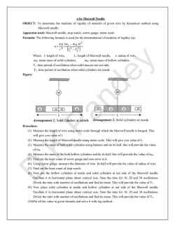
~rectrlc
Equi pments
.. -_ .. Q5
- - fj
:::l :>
4).
fF
(~
------
- ~~~
•
~I~~~
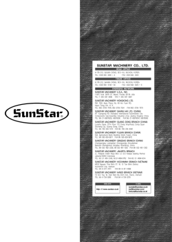
yoqo L-Jl./2P-TH
1·311·8KW
1700I~QlJO(.r/11Un.)
j()()-/527
-15'17
-
-
~---
69
Electric Equi pments
ZttN
--.---
r
I: IfiT
I
I: I
:
Hz5S-IO/R 05
.
r(
,
II
.
•
I t
I lt1
I
I:
I
: L..:.--L .~
••
h..
I
~
YC/~VJ.-1)
2,HP liP
/100 (t/1IfJ7l.)
100-2522
-2592
-5522
-5592
70
I
....
L ..__. _ _
-
f
N
~
-
•
N •
. TI
t::.
~
n
6DHz
Electric Equi pments
___
__
~_s
Hz5B-IO/M5
,--
-
r
ii !0
I!: L. I
::
':)
>
··-l
~
I~-J..-.
i
I
I
,
.
:
I~~
i
D-
>- ::>
·
L . - . ~~ . ~
-~
2HP
4f'
t700( r/milt)
100-1529
-1599
-71
Electric Equipments
THE DETAILED LIST OF ELECTRIC EQUIPMENT
CODE
NAME
DESCRIPTION
TYPE AND TFCHN
ICALDETA
QUANTITY
REMARK
100
-1527
YD90L-4/2P-TH(BS)
220V 60Hz 1.3/1. 8KW
-1597
Milling head
motor
100
YHY(BS)
-1529
220V 60Hz 4P 2HP
~1599
1
M
(Special motor)
(BS) *
220V 60Hz 4P 2HP
100
YC10024D
Single Phase
-2522
-2592
motor of milling
head
YCI0024-D
-5522
(BS)
-5592
220V 60Hz 4P 2HP
HzSB-1O/T21-TH
QS
1
Switch
Hz5B-1O/R05-TH
-72
pz
--
~
-
._----
-
73
© Copyright 2026 Paperzz