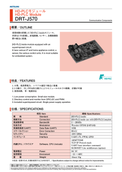
mxchipWNetTM-DTU firmware
Reference
mxchipWNet-DTU
UART <> Wi-Fi Firmware
Manual
4.1
Dateпјљ2014-03-12
Reference manual
Overview
mxchipWNetTM firmware is a software system
running run on EMW Wi-Fi modules developed
by MXCHIP. These firmware embedded with
multiple M2M applications, TCP/IP stack and WiFi driver can greatly reduce your development
time and improve competitiveness on your M2M
products.
Firmware: mxchipWNetTM-DTU is used to
implement the Wi-Fi data transmission on serial
devices. Two primary functions are provided:
EMSP command and direct data transmission
between UART and Wi-Fi. It is widely used in
establishing wireless communication on serial
devices.
Main functions:
Two working modes: EMSP command
TCP/IP features:
mode and direct data transmission mode
пЃ¬
DHCP client and server
пЃ¬
Multiple configuration interface
пЃ¬
DNS, mDNS (bonjour)
пЃ¬
Build-in web site
пЃ¬
Two sockets working at the same time
пЃ¬
Firmware updating using serial and web
пЃ¬
TCP client/server with keep-alive
пЃ¬
detection and auto reconnection
Wi-Fi driver features:
пЃ¬
WLAN standard: IEEE 802.11 b/g/n
пЃ¬
UDP unicast/broadcast
пЃ¬
RF frequency: channel 1-13 on 2.4GHz
пЃ¬
Support 8 clients in TCP server mode
пЃ¬
Greatly reduce power consumption
пЃ¬
HTTP, FTP and SMTP client
пЃ¬
Roaming between multiple access points
пЃ¬
Sock4/5 proxy
пЃ¬
Support station mode,, soft AP mode
UART features:
and Wi-Fi direct
пЃ¬
Baud rate: 2400-3686400
Security: WEP and WPA/WPA2 PSK
пЃ¬
CTS/RTS hardware flow control
пЃ¬
Multiple UART data package mode
пЃ¬
High-speed data transfer by DMA
пЃ¬
enterprise
пЃ¬
Auto detect security mode
Contents
INTRODUCTION .................................................................................................. 5
LED Functions Controlled by Firmware ...................................................................................... 5
Pin Definition Under mxchipWNetTM-DTU ................................................................................ 6
EMW3280, EMW3160 and EMW3162 ...................................................................................................... 6
EMW3161 ........................................................................................................................................................... 6
Function Description of Each Pin ................................................................................................ 7
Typical hardware connections ..................................................................................................... 9
FIRMWARE WORKING MODES AND SWITCHING ........................................ 11
Working Flowchart ...................................................................................................................... 11
Working Modes ........................................................................................................................... 12
Working Mode after Power On ................................................................................................. 12
Switching between Working Modes ......................................................................................... 13
Default Settings ........................................................................................................................... 14
FUNCTION DESCRIPTION: DIRECT TRANSMISSION MODE ........................ 15
QUICK START ............................................................................................................................... 15
Hardware Connection .................................................................................................................................. 15
Connect to module using Wi-Fi ............................................................................................................... 17
Data transmission between serial port and Wi-Fi ............................................................................. 18
Internal mechanism of Direct Transmission Mode ................................................................. 20
Serial Port=>Wireless Network................................................................................................................ 20
2
Wireless Network => Serial Port ............................................................................................................. 23
Half Duplex Mode (HDC mode) ................................................................................................ 24
FUNCTION DESCRIPTION: EMSP COMMAND MODE ................................... 26
QUICK START ............................................................................................................................... 27
Hardware Connection .................................................................................................................................. 27
Send EMSP command using EMW Tool Box ....................................................................................... 27
EMSP Command Specification .................................................................................................. 28
Command Description ................................................................................................................ 29
Static Configuration Commands ............................................................................................................. 30
Dynamic Control Commands .................................................................................................................... 38
METHODS OF CONFIGURATION ..................................................................... 42
Build-in Web Pages Method ...................................................................................................... 42
EMSP Commands Method ......................................................................................................... 43
Near-Field-Communication Method ......................................................................................... 43
Wi-Fi Protected Setup (WPS) ..................................................................................................... 43
Easy Link Method ........................................................................................................................ 44
NETWORK SERVICES ........................................................................................ 47
Use mDNS (Bonjour) Service to find module in local network ............................................. 49
MAC/iOS Example: ........................................................................................................................................ 49
Windows Example: .......................................................................................................... й”™иЇЇ!未定义书зѕгЂ‚
Android example: ............................................................................................................ й”™иЇЇ!未定义书зѕгЂ‚
3
Use UDP broadcast to find module in local network ............................................................. 51
DHCP Server ................................................................................................................................ 52
SALES INFORMATION ...................................................................................... 53
TECHNICAL SUPPORT ...................................................................................... 54
4
Introduction
mxchipWNetTM firmware is a software system running run on EMW Wi-Fi modules
developed by MXCHIP. These firmware embedded with multiple M2M applications,
TCP/IP stack and Wi-Fi driver can greatly reduce your development time and improve
competitiveness on your M2M products.
One of the firmware: mxchipWNetTM-DTU is used to implement the Wi-Fi data
transmission on serial devices. Two primary functions: EMSP command and direct data
transmission between UART and Wi-Fi are provided. It is widely used in establishing
wireless communication on serial devices.
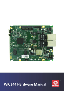
mxchipWNetTM-DTU can run on: EMW3280, EMW3161, and EMW3162. LEDs and pins
on these module are defined to a specified function which is described in 1.1 and 1.2:
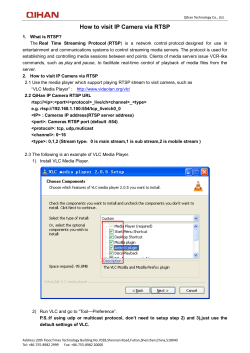
LED Functions Controlled by Firmware
D1
D1
D2
EMW3280
EMW3161
D2
D2
D1
D1
EMW3162
EMW3160
LED function list
Name
D1
D2*
Function description
On
Firmware initialize successful
Off
Firmware uninitialized, or deep sleep mode
Flash
Firmware update mode
On
Wi-Fi connected, DHCP negotiate success
Off
Wi-Fi disconnected
Keep
Data transmission/WPS negotiating/EasyLink
Flashing
mode
* D2 led is available on EMW3280, EMW3162 and EMW3160, and you can also
connect an external led from pin 16. D2 is not existed on EMW3161 module, so you
should connect an external LED from pin 36 on EMW3161.
5
Pin Definition Under mxchipWNetTM-DTU
EMW3280, EMW3160 and EMW3162
EMW3280, EMW3160 and EMW3162 Pinouts
Pins
Pin Name
Pins
Pin Name
1
NFC_SCL
16
2
NFC_SDA
17
nRESET(IN)
3
NC
18
IO1
4
NC
19
NC
5
WPS/Default (IN)
20
nUART_RTS(OUT)
6
NC
21
nUART_CTS(IN)
7
NC
22
UART_TXD(OUT)
8
NC
23
UART_RXD(IN)
9
NC
24
VDD
10
NC
25
GND
11
EasyLink/Default (IN)
26
NC
12
NC
27
NC
13
NFC_INT
28
NC
14
LoPow(IN) *
29
nWAKE_UP(INпј‰
15
GND
30
STATUS(IN)
LED (OUT)
BOOT(IN)
* LoPow function is only available on EMW316x modules.
6
EMW3161
EMW3161 Pinouts
Pins
Pin Name
Pins
Pin Name
6
NFC_INT
39
STATUS(IN)
11
WPS/Default (IN)
40
nRESET(IN)
12
EasyLink/Default (IN)
46
nUART_RTS(OUT)
21
IO1
45
nUART_CTS(IN)
24
LoPow(IN) *
47
UART_TXD(OUT)
28
NFC_SCL
48
UART_RXD(IN)
29
NFC_SDA
41,44,49
GND
42,43
VDD
Other
NC
LED (OUT)
36
BOOT(IN)
38
nWAKE_UP(IN)
Function Description of Each Pin
Function description
Pin
Type
Function
VDD
3.3V DC power input.
GND
Grounding.
NFC_SCL
O
IIC clock (connect to NFC tag EMF2104)
NFC_SDA
I/O
IIC data (connect to NFC tag EMF2104)
NFC_INT
I
WPS/Defaul
t
EasyLink/
Default
Interrupt input (connect to NFC tag EMF2104)
п‚· Pull down and up: enter Wi-Fi protected setup(WPS)
I
п‚· Double click: enter one step configuration method: EasyLink
п‚· Pull down and keep for 5 seconds: restore all settings to default.
This pin is only available on EMW316x modules
I
п‚· Pull down and up: enter one step configuration method: EasyLink
п‚· Pull down and keep for 5 seconds: restore all settings to default.
7
Pin
Type
Function
UART_RXD
I
UART Data input.
UART_TXD
O
UART Data output.
nUART_CTS5
I
UART clear to send, active low.
nUART_RTS5
O
UART is ready to receive, active low.
Control the module’s MCU low power mode:
I
LoPow
п‚· Pull up: Exit sleep mode
п‚· Pull down: Enter sleep mode
Set the operation mode:
STATUS
I, PU1
п‚· Pull up: enter the direct data transmission mode
п‚· Pull down: enter the EMSP command mode
Refer chapter 2 for details.
Module enter deep sleep mode if the WAKE_UP pin is pulled low,
WAKE_UP
I, PU
and wake up while the WAKE_UP pin is pulled high.
Reset is needed to wake up EMW3161 from deep sleep mode.
nRESET6
I, PU
Pull down this pin for 1Ојs to reboot the module.
BOOT signal is detected to enter the different working mode when
module is powered on, Refer chapter 2 for details.
I, PU
LED/
п‚· Pull up: Boot to normal working mode.
п‚· Pull down: Boot to special working modes (firmware update
BOOT
mode or test mode).
O
NC7
LED pin has the same function as led D2, This signal is active low.
No function. (IO1 function is configured by firmware)
FC mode: Used as a serial data frame controller in direct data
I7
transmission mode.
п‚· Pull down: Module stores the received serial data in RAM
п‚· Pull up: Build up TCP/UDP package with the serial data in RAM
IO1
HDC mode: Used as a Half-duplex Controller.
Output a high level signal while sending a serial data, otherwise,
O7
output a low level
This function can also be used to wake up host before send any
UART data.
NC
Undefined IOs. Leave them floating or grounding.
1.
PU: The pin is at high level if no external signal is asserted.
2.
PD: The pin is at low level if no external signal is asserted.
3.
UART signals includes UART_TXDпјЊUART_RXDпјЊUART_RTS and UART_CTSгЂ‚
4.
Only VDD, GND UART_TXD and UART_RXD are needed in a simplest connection.
8
5.
It is recommend that using UART_RTS and UART_CTS signal in serial interface.
When using hardware flow control, firmware would not lost any serial data under
TCP connection.
6.
nRESET signal should not be forced to high by external circuit, internal watch
dog function would not work correctly in this condition, if nRESET is controlled
by an IO signal, this IO should be set to open drain modeгЂ‚
7.
Use EMSP command to set the different function on IO1, “NC” is the default
state.
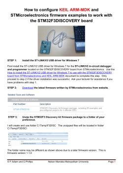
Typical hardware connections
Figure 1.1 TTL/CMOS UART serial interface
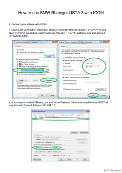
9
Figure 1.2 RS232 UART serial interface
Figure 1.3 RS485 serial interface
10
Firmware Working Modes and Switching
Working Flowchart
11
Working Modes
Direct Transmission Modeпјљ
Firmware automatically connects the wlan according to the predefined settings, then
package the serial data into TCP/UDP packets and send them to wlan automatically. It can
also receive TCP/UDP packets from wlan and send them to serial interface. Firmware
enter this mode when STATUS signal is high.
EMSP Command Modeпјљ
In this mode, you can use EMSP commands to control module and configure
firmware’s parameters from serial port interface. Enter this mode when the STATUS pin
is low. Please refer chapter 4 for details.
Forced EMSP Command Modeпјљ
This mode has the same functions as EMSP command mode, but firmware doesn't
check STATUS pin before entering this mode, and you can't quit this mode by assert high
on STATUS pin of course. Use EMSP command EMSP_CMD_RESET or assert the nRESET
pin to quit this mode.
Use this mode if you want to use EMSP command but STATUS pin is not connected.
Firmware Update Modeпјљ
Firmware automatically connect the wlan according to the predefined settings, then
package the serial data into TCP/UDP packets and send them to wlan automatically using
TCP/UDP protocol. It can also receive TCP/UDP packets from wlan and send them to
serial interface. Firmware enters this mode when STATUS signal is high.
Test Modeпјљ
Firmware automatically connect the wlan according to the predefined settings, then
package any data received from serial interface into TCP/UDP packets and send them to
wlan automatically. It can also receive TCP/UDP packets from wlan and send them to
serial interface. Firmware enters this mode when STATUS signal is high.
Working Mode after Power On
Firmware boot to different working depends on BOOT/STATUS signals.
Boot Options
BOOT
STATUS
Working Mode
0
0
Test Mode
0
1пј€Defaultпј‰
Firmware Update Mode
1пј€Defaultпј‰
0
EMSP command Mode
1пј€Defaultпј‰
1пј€Defaultпј‰
Direct Transmission Mode
12
If BOOT=1, firmware will also check the continuous serial input during initializing
with default serial settings: 115200/8/n/1. Initializing time is different depends on
module’s model, but would not exceed 750ms.
Special serial input when booting
BOOT
STATUS
UART INPUT
Function
1
X
Receive three 0x31
Enter forced EMSP command mode
1
X
Receive three 0x20
Restore all settings to default
1
X
Receive three 0x32
Use WPS to negotiate with AP in 5 seconds
Switching between Working Modes
Direct Transmission Mode в†’ EMSP Command Mode
1.
Pull down the STATUS pin.
2.
Send any EMSP command, until correct respond is returned.
3.
Firmware enters EMSP Command Mode.
EMSP Command Mode в†’ Direct Transmission mode
1.
Send EMSP_CMD_START command to connect the network. (If connected, skip
step 1)
2.
Pull up the STATUS pin
3.
Firmware enters Direct Transmission mode.
13
Default Settings
Customer can have their own factory settings when purchasing the module, contact
MXCHIP for further information.
Default settingsпјљ
WLAN settings:SSID:“MXCHIP_XXXX” (XXXX=the last 2 bytes of module’s MAC
address) пјЊSoft AP mode
UART settingsпјљ115200/8/n/1
IP Address: 192.168.1.1/255.255.255.0, DHCP server enabled. Bonjour service
enabled.
TCP Server mode, Portпјљ8080
If you need to restore the default settings, you can
п‚«
Send 0x20 to module’s serial port 3 times when firmware is initializing
Or
п‚«
Push down WPS/Default or EasyLink/Default pin for 5 seconds
14
Direct Transmission Mode
Direct Transmission Mode adds the wireless data transmission on serial devices, and
simplify the user’s development significantly.
Details of the Direct Transmission Mode:
Transferring data in a reliable network must follow a certain kind of format and
protocol. For example, when transferring data in WLAN, we need to pack data into TCP
data packet, and then according to receiver's address, pack the TCP package into the
TCP/IP package with IP information. Therefore, to transfer data in the WLAN, we need to
develop the network protocol stack first. These protocol stacks exist in PC’s operation
system but is hard to run on embedded systems, which have very limited resources.
mxchipWNetTM-DTU can pack the serial data into TCP/IP package automatically, and
also unpack the payload from the TCP/IP package, send the payload to serial interface. So
firmware does not require a specific data format on serial interface. Firmware hides the
complicate network transmission function from the user's applications, it looks like that
sender and receiver are connected with a traditional serial cable. And this is why it's
called the Direct Transmission Mode.
Several major functions are adopted in this mode:

All of the serial data received are transferred to payload of the TCP/UDP package
on a specific port and delivered automatically.

Fetch the entire payload from the TCP/UDP package on a specific port and send
them to serial port.

All Wi-Fi network connections and services are established automatically
according to the predefined settings.

Auto recovers from any network failure.
Two ways to enter the Direct Transmission Mode:

Pull up the STATUS signal and reboot.

Start the network connections in EMSP command mode, and then pull up the
STATUS pin.
QUICK START
The following steps are listed to present how to demonstrate the Direct Transmission
Mode on module, which has been configured with a factory setting from MXCHIP.
Hardware Connection
1.
Set the BOOT pin and STATUS pin to high before powered on
According to Table 2.1, we need to set the correct signal: BOOT=1, STATUS=1 to
15
enter the Direct Transmission Mode. The required inputs are the default state on the two
pins, and if you are using an EMB-380-S test board, set the switchers as follow.
Figure 3.1 EMB-380-S switchers
Switchers
2.
Connect module to PC using a serial cable.
An USB-serial converter is available on EMW-380-S2 test board. It’s very easy to
connect the test board to PC via a mini USB cable. Set the jump J3, J4, J5, J6 to USB side
and download the USB driver from http://www.ftdichip.com/Drivers/VCP.htm
Figure 3.2 EMB-380-S2 switchers to use serial/USB converter
16
3.
Power on and restore the module with default settings.
Use the methods listed in chapter 2.5 to restore the default settings. If you are using
test board EMB-380-S2, it is easy to push down WPS/Default button for 5 seconds until
the module reboot.
Push down for 5 seconds
Connect to module using Wi-Fi
Open the Wireless connection window on PC, you can find a Wi-Fi network named
“MXCHIP_XXXXXX” by searching available network nearby. “XXXXXX” is the last 3
bytes of module’s MAC address. Connect this network!
Figure 3.3 Connect to module
Connect this network
Once connected to the network, your pc would be assigned an IP address which
within the scope of 192.168.1.XX. Now you can communicate with module, which has the
static IP address: 192.168.1.1, and you can also locate module’s address by bonjour
service. Login to module’s build-in web pages if you want to change module’s
configuration, but we do not need to do this in this simple demonstration
Figure 3.4 Bonjour and WEB service
17
Data transmission between serial port and Wi-Fi
Use TCP&UDP debugger or terminal software to create a TCP client and connect to
module on port 8080.
Typical Terminal software: HyperTerminal on Windows XP or SecureCRT on both
Windows and MAC.
Note: download TCP&UDP debugger software at
http://www.mxchip.com/uploadfiles/soft /EMW/TCP&UDP_Debugger_Setup.zip.
Figure 3.5 Create TCP conection to module on SecureCRT
Open terminal software and connect to module from serial port with 115200 baud
rate, 8 data length, 1 stop bit, and no flow control.
Figure 3.6 Create serial conection to module on SecureCRT
18
You may find that: any input in the serial terminal would be displayed on network
terminal and any input on network terminal would be transferred to serial terminal.
Figure 3.6 Data transimission between two type of interface
19
Internal mechanism of Direct Transmission Mode
Under Direct Transmission Mode, all of the data conversion between serial port and
network is performed automatically by firmware, and no need to be concerned in an
ordinary use. Connect this network!
Serial Port=>Wireless Network
A flowchart of forwarding serial data to network:
Firmware has three buffer used for temporary storage for serial data:
1.
DMA Buffer: Temporary store the serial data received from DMA controller
2.
UART Data Buffer: Firmware copy data from DMA buffer if DMA buffer is full
3.
TCP Window Buffer: The data in TCP windows size are ready to be transferred to
network handled by TCP/IP stack
A brief description of the processing transfer data from serial port to network:
1.
Hardware DMA controller deliver the received serial data to its DMA buffer. This
part of the operation is completed by the DMA controller, and does not cost any
CPU processing time.
2.
Firmware copy serial data from DMA buffer to UART data buffer when DMA
buffer is full or timeout. DMA buffer size and timeout can be configured by DMA
buffer size in order to balance the performance and delay. A larger size of DMA
buffer size reduce the frequency of the copy operation and give more CPU time
to processing network stacks that improve the system’s MAX of data
20
transmission speed in but reduce the system's real-time.
DMA buffer size

256 bytes: Copy immediately if receive 256 bytes or delay 100ms

128 bytes: Copy immediately if receive 128 bytes or delay 100ms

64 bytes: Copy immediately if receive 64 bytes or delay 100ms

32 bytes: Copy immediately if receive 32 bytes or delay 100ms

16 bytes: Copy immediately if receive 16 bytes or delay 100ms

8 bytes: Copy immediately if receive 8 bytes or delay 100ms

No DMA buffer (default): Copy immediately if receive any serial data
3.
Copy the data from UART data buffer to TCP window buffer according to rules
defined by Conversion Mode. Data in TCP window buffer can be packaged in to
the payload of one TCP/IP frame.
Conversion Mode has defined several conversion rules and will add more in future.

Data Flowпјљ
Firmware do not analyze data in UART data buffer but send them immediately if data
exist. The content and length of the TCP/IP packages generated in this mode cannot be
predicted but have the best real-time performance.

Delay 20ms

Delay 50ms

Delay 100ms(default)

Delay 150ms

Delay 200ms
Similar in Data Flow mode, firmware does not analyze the data stored in UART data
21
buffer, but send them in a delay if UART Data Buffer is not full. More serial data existed in
one TCP/IP package in this mode, and the total quantity of the TCP/IP packages is
reduced that improve the performance of network.

Package Mode 1

Package Mode 2
Firmware analyzes data in UART data buffer and packs the serial data which fit the
predefined package structure. In this mode, a predefined serial data frame is only existed
in one TCP/IP package, so it simplify the data analyzing operation on the other side of
the network.
Data structure in Package Mode 1:
0x7E+Len (1 byte) +data+0xCE, (Length = data size + 1).
Firmware packs the full data frame into one TCP/IP package.
Example: Serial data: 7E 06 11 22 33 44 55 CE. Data in TCP/IP package: 7E 06 11 22 33
44 55 CE
Data structure in Package Mode 2:
0x7E+Len1 (1 byte) + Len2 (1 byte) +data+0xCE, (len1<<8+len2 = data size + 1).
Firmware only packs the data part into one TCP/IP package.
Example: Serial data: 7e 00 09 11 22 33 DD CE AA 12 DD CE. Data in TCP/IP package:
11 22 33 DD CE AA 12 DD

FC mode
Pin: IO1 has configurable function defined by IO1Mode. When IO1 is defined to FC
mode, IO1 detect the input signal:
пѓ�
IO1=0: Firmware stores the received serial data in UART Data Buffer
пѓ�
IO1=1: Build up TCP/UDP package with the serial data in UART Data Buffer
Note: Set DMA Buffer Size to Zero, while using HC mode on IO1.
4.
Step 1-3 are circled, firmware store the serial data to UART Data Buffer, then pack
the data to TCP/IP package according to different method, TCP/IP stack and the
IEEE 802.11 MAC/PHY send these data in wireless network at last.
22
5.
If network is blocked, it result the TCP window Buffer filled with data, then no
more data can be packed into TCP/IP package, it make the DMA Buffer and UART
Data Buffer also full of data. Under this situation, serial port cannot receive any
more data that lead to the loss of data on serial port.
If Hardware Flow Control function is enabled, module would assert RTS signal under
such situation to announce that sender should not send any more serial data. It can
prevent the loss of data when network is blocked.
Note: Set the DMA Buffer Size above 16 bytes when you enable hardware flow
control function on serial port.
Wireless Network => Serial Port
It is quite simple to deliver data from network to serial port, because a TCP/IP
network can adjust the data traffic automatically according to the data rate on serial
port.гЂ‚The flow chart is as below:
TCP/IP stack store the data in buffer and send them to serial port using DMA
controller.
23
The UART data transmission is much slower than network data. In hardware flow
control mode, the receiver may block the data sending on module by asserting CTS
signal. Therefore, it is very common to see the TCP Window Buffer becomes full. When
this happens, the receiving of the network data is blocked; it will reduce the network
transmission rate. However, due to the TCP’s re-sending mechanism, the network data
will not be lost. The following diagram shows an example where the module
automatically stops sending the data to UART due to a CTS signal.
Half Duplex Mode (HDC mode)
Half Duplex Mode is primarily used in RS485 communication. When the module is
attached to a RS485 voltage converter, this mode controls the input and output state of
the converter. A typical RS485 communication hardware connection is shown in Figure
1.3.
We can achieve this function by setting IO1 to HDC. IO1 in HDC Mode has the
following function:
1.
When the module receives UART data, IO1 outputs low (default state)
2.
When the module sends out UART data, I01 outputs high.
24
25
EMSP Command Mode
EMSP command is an ideal tool to communicate with mxchipWNetTM-DTU firmware.
Not like traditional ASCII code (like AT command), EMSP command is fast, reliable and
easy programming for embedded device. Use EMSP commands, you can:

Set the firmware’s configuration

Execute Wi-Fi and TCP/IP operations

Send or receive data on TCP/IP network, execute HTTP, FTP protocol operations
Any data input from serial must meet the specifications of EMSP command format, if
not, firmware will not respond and the serial data is lost.
To enter the EMSP command mode, you just need to pull the module’s STATUS pin
to low. If you are using EMW-380-S series test board, please set the STATUS switch to low.
Communication model
The command mode uses the typical master-slave communication protocol. The
sender acts as the master/host, while the module is the slave/client. The communication
starts with sender sending request to module, followed by module responding the
request.
All the requests and responses go through verification and calculation to ensure the
integrity and reliability of communication.
When the firmware initialization completes, the serial device can used the protocol
provided by the specification to communicate with the module. Because each command
in the communication protocol has different function, the processing time is not always
the same. Therefore, you should wait for module’s return value after sending the next
request.
Communication interface
1.
Serial port interface
In default settings, the parameters of serial port interface are: 8 bits, no parity check,
1 stop bit, 115200 baud rate. Users can modify these parameters based on their
requirement.
2.
Wi-Fi interface
You can send EMSP commands to module from UDP protocol on port 8089 when
module is connected to a wireless network. So you can send a command to all of the
local modules using a UDP broadcast, and each module can return the result by an UDP
unicast package.
26
QUICK START
The following steps are listed to present how to demonstrate the EMSP command
mode using a serial port.
Hardware Connection
1.
Set BOOT pin = 1, STATUS = 0 before powered on
According to Table 2.1, we need to set the correct signal: BOOT=1, STATUS=0 to
enter EMSP Command Mode. If you are using an EMB-380-S test board, set the switchers
as follow.
Figure 4.1 EMB-380-S switchers
Switchers
2.
Connect module to PC using a serial cable.
Please refer to chapter 3.1.1 for details.
Send EMSP command using EMW Tool Box
EMW Tool Box is a software running on Windows PC, it can generate the required
EMSP command according to the function selected on its window. Download this
software at
http://www.mxchip.com/uploadfiles/soft/EMW/EMWToolBox_Setup.zip.
First, you need to open the correct COM port that is connected to module. And then
click the “Get FW version” button, and the firmware version will be displayed on the
right side of the button.
The EMSP commands sent and received will be displayed on the right side of the
software; they are very useful if you are writing your own module controller software.
If you are trying to change settings, click the “Load Paras from Module” button
first to read the parameters from module, then change the target parameters, and click
“Save Paras to Module” button to save your settings.
27
Click “Startup Network” button to start Wi-Fi connection and TCP/UDP data link.
Figure 4.2 EMW Tool Box
EMSP Command Specification
EMSP command consists of a protocol header (8 bytes) and a data block. The length
of the data block is not fixed, but can be no longer than 256 bytes. The command format
is shown as follows
[<command><length><result><head checksum>][<data><data checksum>]
Protocol Header
A protocol header consists of one command segment (2 bytes), one length segment
(2 bytes), one result segment (2 bytes, returned by the module), and a header checksum
(2 bytes). The format is shown as follows
[<command><length><result><head checksum>]
<command>пјљCommand segment, 2 bytes
<length>пјљLength segment, 2 bytes. This is the length of the whole EMSP command,
including the protocol header and the data block.
<result>пјљResult segment, 2 bytes. The request and response should use the same
protocol header; this segment is only effective in the response packet.
28
<head checksum>пјљ Header checksum, 2 bytes. It is used to verify the integrity of
the protocol header.
Data block
The data block includes all the data used by the current command, and one data checksum (2 bytes) at
the end. The format is shown as below:
[<data><data checksum>]
<data>пјљData. Its length is not fixed, can be calculated from the length segment in the protocol
header.
<data checksum>пјљData checksum, 2 bytes. It is used to verify the integrity of the data block.
Note: The checksums of the protocol header and data block are independent. The checksum in
protocol header only verifies the protocol header while the checksum in the data block only
verifies the data block.
Verification algorithm
Please reference the following C code:
u16 calc_sum(void *data, u32 len)
{
if (len){
u32 cksum=0;
cksum += *(u8 *)p;
__packed u16 *p = data;
}
while (len > 1){
cksum = (cksum >> 16) + (cksum & 0xffff);
cksum += *p++;
cksum += (cksum >>16);
len -=2;
return ~cksum;
}
}
Command Description
There are two kinds of EMSP commands:
Static configuration commands
These commands are used to configure and read module’s parameters. These
parameters will be written into module’s Flash, hence it normally requires reboot to
make these commands take effect. If the module enters the data mode after reboot, the
module will automatically establish the network communication network based on the
parameters set by these commands.
29
Dynamic control commands
These commands can dynamically control module’s different functions, temporarily
change working parameters, send or receive data. However, any changes resulted by
these commands will not be saved in module. Once rebooted, the changes are lost. The
dynamic control commands are introduced to increase module’s flexibility.
The following are the definitions to the date transmitted in the commands
typedef unsigned char
u8пјљ
u8 represent 8bit data
typedef unsigned short int
u16пјљ
u16 represents 16bit data
typedef unsigned int
u32пјљ
u32 represents 32bit data
Static Configuration Commands
EMSP_CMD_GET_CONFIG (COMMAND ID 0002)
This command retrieves basic configuration information from the module.
Host sends: 02 00 0A 00 00 00 F3 FF FF FF
Module returns: 02 00 A9 00 01 00 53 FF <data><data checksum>
<data> structure:
Basic Parameters
NAME
Wi-Fi
mode
TYPE
LENGTH
FUNCTION
1: Station mode
U8
1
2: Soft AP mode
3: Station mode + Soft
AP mode( the Soft AP parameters in this mode is defined in
command: EMSP_CMD_SET_DUAL_UAP)
SSID
U8
32
Wi-Fi network name
WEP Key
U8
16
WEP security key is available if Security Mode is set to WEP
The key length of WEP security key available if Security
Mode is set to WEP
WEP key
length
U8
1
0: The same as setting SECURITY MODE to NONE
5: WEP security key is 10 hex numbers (5 ACSII characters)
13: WEP security key is 26 hex numbers (13 ACSII
characters)
Module’s static IP address, it will be overridden if
Local IP
address
U8
16
firmware get an address successfully from DHCP server.
It is presented by string using dot-decimal notation.
Example: “192.168.0.1”
30
NAME
TYPE
LENGTH
FUNCTION
The IP address where module is trying to connect or send
Remote IP
address
U8
16
data if module is setting to TCP client mode and UDP unicast
mode. It is ignored if DNS is enabled.
The format is the same as Local IP address.
Net mask while using a static IP address, same format as
Net mask
U8
16
Gateway
U8
16
Port_H
U8
1
Upper byte of the TCP/UDP socket port
Port_L
U8
1
Lower byte of the TCP/UDP socket port
Protocol_1
U8
Local IP address.
Gateway IP address while using a static IP address, same
format as Local IP address.
1
DHCP
U8
1
Protocol_2
U8
1
Protocol_1
Protocol_2
Function
0
0
TCP Server Mode
0
1
UDP Broadcast Mode
1
0
TCP Client Mode
1
1
UDP Unicast Mode
0: Use static local IP address
1: Use DHCP service to get local IP address
Refer to Protocol_1
Serial port baud rate:
Baud Rate
DMA
Buffer Size
Flow
U8
1
0: 9600
1: 19200
2: 38400
3: 57600
4:115200
5:230400
6: 460800
7:921600
8:1843200
9: 3686400
10: 4800
11: 2400
12: 1200
3: 32bytes
DMA Buffer Size:
U8
1
0: No DMA buffer
1: 8 bytes
2: 16bytes
4: 64 bytes
5:128 bytes
6:256 bytes
U8
1
0: Disable
Parity
U8
1
0: None
Data Bits
U8
1
0: 8bits
Stop Bits
U8
1
0: 1bits
1: 0.5bits
IO1
U8
1
0: None
1: FC Mode
U8
1
0: WEP
1: WPA/WPA2 PSK
U8
32
Control
Security
Mode
Key
1: Enable
1: Even
2: Odd
1: 2bits
1: 1.5bits
2: HDC Mode
2: None
3: WEP Hex
4: Auto
EMSP_CMD_SET_CONFIG
WPAпјЊWPA2 PSK Security Key
(COMMAND ID 0003)
This command configures module’s parameters. Once changed, the module has to
31
be rebooted in order for these parameters to take effect.
Host sends: 03 00 A9 00 00 00 53 FF <data><data checksum>
Module returns: 03 00 A9 00 01 00 52 FF <data><data checksum>
Check Table 4.1 for details in <data> structure.
EMSP_CMD_SET_DNS (COMMAND ID 0052)
This command enables DNS resolution function and configures DNS related settings.
Host sends: 52 00 5E 00 00 00 4F FF <data><data checksum>
Module returns: 52 00 0A 00 01 00 A2 FF FF FF
<data> structure:
DNS Parameters
NAME
TYPE
LENGTH
ENABLE
U32
1
Domain
Name
FUNCTION
0: DNS disabled
1: DNS enabled
The string of domain name where module is trying to
U8
64
connect or send data if module is setting to TCP client mode
and UDP unicast mode.
DNS server IP address, it will be overridden if firmware get
DNS
Server IP
U8
16
an address successfully from DHCP server.
Address
It is presented by string using dot-decimal notation.
Example: “192.168.0.1”
EMSP_CMD_GET_DNS (COMMAND ID 0053)
This command gets the module’s DNS related parameters.
Host sends: 53 00 0A 00 00 00 A2 FF FF FF
Module returns: 53 00 5E 00 01 00 4F FF <data><data checksum>
Check Table 4.2 for details in <data> structure.
EMSP_CMD_SET_EXTRA_SSID (COMMAND ID 0064)
This command sets extra four Wi-Fi network parameters. Module can roam in these
predefined Wi-Fi networks (Wi-Fi network defined in EMSP_CMD_GET_CONFIG is also
included) under station mode.
Host sends: 64 00 0E 01 00 00 8D FE <data><data checksum>
Module returns: 64 00 0A 00 01 00 90 FF FF FF
<data> structure:
32
Extra Wi-Fi networks Parameters
NAME
TYPE
LENGTH
SSID_1
U8
32
Wi-Fi network 1 name
Key_1
U8
32
Security key of Wi-Fi network 1
U8
1
SSID_2
U8
32
Wi-Fi network 2 name
Key_2
U8
32
Security key of Wi-Fi network 2
U8
1
SSID_3
U8
32
Wi-Fi network 3 name
Key_3
U8
32
Security key of Wi-Fi network 3
U8
1
SSID_4
U8
32
Wi-Fi network 4 name
Key_4
U8
32
Security key of Wi-Fi network 4
U8
1
Security
Mode_1
Security
Mode_2
Security
Mode_3
Security
Mode_4
FUNCTION
Wi-Fi security 1 mode
0: WEP
1: WPA/WPA2 PSK
2: None
4: Auto
2: None
4: Auto
2: None
4: Auto
2: None
4: Auto
Wi-Fi security 2 mode
0: WEP
1: WPA/WPA2 PSK
Wi-Fi security 3 mode
0: WEP
1: WPA/WPA2 PSK
Wi-Fi security 4 mode
0: WEP
1: WPA/WPA2 PSK
EMSP_CMD_GET_EXTRA_SSID (COMMAND ID 0065)
This command gets extra four Wi-Fi network parameters.
Host sends: 65 00 0A 00 00 00 90 FF FF FF
Module returns: 65 00 0E 01 01 00 8B FE <data><data checksum>
Check Table 4.3 for details in <data> structure.
EMSP_CMD_SET_EXTRA_SOCKET (COMMAND ID 0069)
This command sets an extra socket connection. Serial data can be delivered by both
main socket and this extra socket, and any data on these sockets can be sent to serial
port.
Host sends: 69 00 4D 00 00 00 49 FF <data><data checksum>
Module returns: 69 00 0A 00 01 00 8B FF FF FF
<data> structure:
Extra Wi-Fi networks Parameters
NAME
TYPE
LENGTH
Protocol
U8
1
FUNCTION
0: TCP Server Mode
1: TCP Client Mode
2: UDP Unicast Mode
3: UDP Broadcast Mode
33
4: Disable
NAME
TYPE
LENGTH
Port
U16
1
U8
64
Remote
address
FUNCTION
Socket port number
Remote server address used in TCP client mode and UDP
unicast mode. Input IP address or domain name.
EMSP_CMD_GET_EXTRA_SSID (COMMAND ID 006A)
This command gets configuration of the extra socket connection.
Host sends: 6A 00 0A 00 00 00 8B FF FF FF
Module returns: 6A 00 4D 00 01 00 47 FF <data><data checksum>
Check Table 4.5 for details in <data> structure.
EMSP_CMD_SET_KEEPALIVE (COMMAND ID 006B)
When working as a TCP and data is not transmitting, module sends keep-alive
package periodically, and the other side should returns to module. If module does not
receive the returned keep-alive package, module will start to count the number of
failures. If the count exceeds the max retry number, module will terminate the current
TCP link, recycle the resources and try to reconnect the TCP server. The count will return
to zero if the keep-alive package is returned or data transmission is successful.
Time needed to detect a broken TCP link: Retry number x Retry interval
Host sends: 6B 00 12 00 00 00 82 FF <data><data checksum>
Module returns: 6B 00 0A 00 01 00 89 FF FF FF
<data> structure:
TCP Keep-alive Parameters
NAME
Retry
number
Retry
interval
TYPE
LENGTH
FUNCTION
U32
1
Max TCP keep-alive package retry number
U32
1
Time interval between two retry (Unit: second)
EMSP_CMD_GET_KEEPALIVE (COMMAND ID 006C)
This command gets TCP keep-alive parameters
Host sends: 6C 00 0A 00 00 00 89 FF FF FF
Module returns: 6C 00 12 00 01 00 80 FF <data><data checksum>
34
Check Table 4.4 for details in <data> structure.
EMSP_CMD_SET_PS_MODE (COMMAND ID 0063)
This command set IEEE 802.11 power save mode parameters. IEEE 802.11 power save
mode can reduce the RF power consumption when data is not transmitting. When IEEE
power save mode is enabled, 802.11 MAC and PHY will enter sleep mode between two
DTIM intervals.
The DTIM is about 100ms -500ms depends on the settings on the AP.
Every time module wakes up, it will check if AP has buffered data for module and
receive them immediately. After has received them successfully, module will continue to
sleep. But if more data is arrived when module is asleep, module can receive only at the
next DTIM time point. Delay is generated in this situation.
So, after module has received the buffered data, it should not go to sleep
immediately but wait a predefined time. When data is received during this time, no delay
would be generated. The time that module remains awake after receive a Wi-Fi data
package is defined by: Interval x Interval Unit.
Host sends: 63 00 14 00 00 00 88 FF 00 00 E8 03 00 00 C8 00 00 00 4F FB
<data><data checksum>
Module returns: 63 00 0A 00 01 00 91 FF FF FF
<data> structure:
TCP Keep-alive Parameters
NAME
TYPE
LENGTH
ENABLE
U8
1
Interval
Unit
FUNCTION
0: Disable
1: Enable Power Save Mode
0=Millisecond
U8
1
1=Time between two beacon (Defined in
AP)
Default is 0, Millisecond
35
( Not used in EMW316x modules)
NAME
Unicast
Interval
Multicast
Interval
TYPE
LENGTH
U32
1
U32
1
FUNCTION
Stay awake after receive a unicast Wi-Fi package, default is
1000 (1000ms) Not used in EMW316x modules)
Stay awake after receive a multicast Wi-Fi package, default
is 100 (100ms) Not used in EMW316x modules)
EMSP_CMD_GET_PS_MODE (COMMAND ID 0066)
This command gets IEEE power save mode parameters.
Host sends: 66 00 0A 00 00 00 8F FF FF FF
Module returns: 66 00 14 00 01 00 84 <data><data checksum>
Check Table 4.5 for details in <data> structure.
EMSP_CMD_SET_DUAL_UAP (COMMAND ID 0067)
In Station + Soft AP mode, module can communicate with cloud service on the
internet through a wireless router, and accept local controller in soft AP mode. Wi-Fi
parameters in station mode are defined by command: EMSP_CMD_GET_CONFIG. This
command defines the soft AP parameters in this mode.
Host sends: 67 00 4B 00 00 00 4D FF <data><data checksum>
Module returns: 67 00 0A 00 01 00 8D FF FF FF
<data> structure:
Soft AP Parameters in DUAL Mode
NAME
TYPE
LENGTH
SSID
U8
32
Wi-Fi network name
Key
U8
32
Security key
U8
1
Security
Mode
FUNCTION
Wi-Fi security 1 mode(WEP is not supported in this mode)
1: WPA/WPA2 PSK
2: None
EMSP_CMD_GET_DUAL_UAP (COMMAND ID 0068)
This command gets TCP keep-alive parameters
Host sends: 68 00 0A 00 00 00 8D FF FF FF
Module returns: 68 00 4B 00 01 00 4B FF <data><data checksum>
Check Table 4.6 for details in <data> structure.
36
EMSP_CMD_GET_UART_MODE (COMMAND ID 0062)
This command gets the Conversion Mode which package serial data to TCP/IP
package.
Host sends: 62 00 0A 00 00 00 93 FF FF FF
Module returns: 62 00 0B 00 01 00 91 FF <data><data checksum>
<data> structure: (Refer chapter 3.2.1 for the detailed function of each mode)
Conversion Mode Parameters
NAME
Conversio
n Mode
TYPE
U8
LENGTH
1
FUNCTION
0: Data Flow
1: Package Mode 1
2: Delay 20ms
3: Delay 50ms
4: Delay 100ms
5: Delay 150ms
6: Delay 200ms
7: Package Mode 2
EMSP_CMD_SET_UART_MODE (COMMAND ID 0061)
This command sets the Conversion Mode, which package serial data to TCP/IP
package.
Host sends: 61 00 0B 00 00 00 93 FF <data><data checksum>
Module returns: 61 00 0A 00 01 00 93 FF FF FF
Check Table 4.3 for details in <data> structure.
EMSP_CMD_GET_NAME (COMMAND ID 0046)
This command gets module’s name, the name will be presented by bonjour service.
Host sends: 46 00 0A 00 00 00 AF FF FF FF
Module returns: 46 00 32 00 01 00 86 FF <data><data checksum>
Bonjour Name Parameters
NAME
TYPE
LENGTH
Name
U8
40
FUNCTION
The module’s name string with a fixed size of 40 bytes, it
is used by bonjour service.
EMSP_CMD_SET_NAME (COMMAND ID 0047)
This command sets module’s name, the name will be presented by bonjour service.
Host sends: 47 00 32 00 00 00 86 <data><data checksum>
Module returns: 47 00 0A 00 01 00 AD FF FF FF
37
Check Table 4.4 for details in <data> structure.
EMSP_CMD_GET_VER (COMMAND ID 006F)
This command gets module’s firmware version.
Host sends: 6F 00 0A 00 00 00 86 FF FF FF
Module returns: 6F 00 1A 00 01 00 75 FF <data><data checksum>
<data>: Current firmware’s version( 12 characters )
EMSP_CMD_GET_MAC_ADDR (COMMAND ID 000C)
This command gets module’s MAC address.
Host sends: 0C 00 0A 00 00 00 E9 FF FF FF
Module returns: 0C 00 10 00 01 00 E2 FF <data><data checksum>
<data>: The MAC address of the module. It is a hex number with a fixed length of 6
bytes.
Dynamic Control Commands
EMSP_CMD_RESET (COMMAND ID 0001)
This command soft resets the module.
Host sends: 01 00 0A 00 00 00 F4 FF FF FF
Module returns: 01 00 0A 00 01 00 F3 FF FF FF
EMSP_CMD_START (COMMAND ID 0005)
This command enables module’s Wi-Fi connection and TCP connection.
Host sends: 05 00 0A 00 00 00 F0 FF FF FF
Module returns: 05 00 0A 00 01 00 EF FF FF FF
EMSP_CMD_GET_STATUS (COMMAND ID 0008)
This command is used to get the module’s current running status
Host sends: 08 00 0A 00 00 00 ED FF FF FF
38
Module returns: 08 00 0E 00 01 00 E8 FF <data><data checksum>
<data> structure:
Current Running Status
NAME
TYPE
LENGTH
System
U8
1
FUNCTION
Reversed
Bit0=0: Disconnected in station mode
Wi-Fi
U8
1
Bit0=1: Connected in station mode
Bit1=0: Soft AP mode not established
Bit1=1: Soft AP mode established
0: Socket1 is disabled
Socket1
U8
1
1: Socket1 disconnected (Under TCP client mode)
2: No TCP client is connected (Under TCP server mode)
3: Socket1 connected
0: Socket2 is disabled
Socket2
U8
1
1: Socket2 disconnected (Under TCP client mode)
2: No TCP client is connected (Under TCP server mode)
3: Socket2 connected
EMSP_CMD_GET_IP (COMMAND ID 0040)
This command gets the current IP address.
Host sends: 40 00 0A 00 00 00 B5 FF FF FF
Module returns: 40 00 3A 00 01 00 84 FF <data><data checksum>
<data>: ……, The data structure of the data block is shown as follows
Current IP Address
NAME
Local IP
address
TYPE
LENGTH
FUNCTION
Current IP address.
U8
16
It is presented by string using dot-decimal notation.
Example: “192.168.0.1”
Net mask
U8
16
Current net mask
Gateway
U8
16
Current gateway
EMSP_CMD_OPEN_SOCKET (COMMAND ID 0045)
This command establishes the EXTRA TCP/UDP socket connection. The remote server
address in the command could be either an IP address or a domain name.
Host sends: 45 00 4E 00 00 00 6C FF <data><data checksum>
Module returns: 45 00 0A 00 01 00 AF FF FF FF
39
<data> structure:
Open Socket Parameters
NAME
TYPE
LENGTH
Protocol_2
U8
1
FUNCTION
Protocol_1
Protocol_2
Function
0
0
TCP Server Mode
0
1
UDP Broadcast Mode
1
0
TCP Client Mode
1
1
UDP Unicast Mode
Protocol_1
U8
1
Port_H
U8
1
Upper byte of the TCP/UDP socket port
Port_L
U8
1
Lower byte of the TCP/UDP socket port
Server
address
The address of the TCP server or UDP send target.
U8
64
Either domain name or IP address can write to this part.
Example: “192.168.0.1”or “www.google.com”
EMSP_CMD_CLOSE_SOCKET (COMMAND ID 0044)
This command closes the EXTRA TCP/UDP socket.
Host sends: 44 00 0A 00 00 00 B1 FF FF FF
Module returns: 44 00 0A 00 01 00 B0 FF FF FF
EMSP_CMD_WIFI_STOP (COMMAND ID 004A)
This command stops the Wi-Fi connection.
Module returns: 4A 00 0A 00 01 00 AA FF FF FF
EMSP_CMD_WIFI_CONNECT (COMMAND ID 004B)
This command starts the Wi-Fi connection based on the predefined parameters.
Host sends: 4B 00 0A 00 00 00 AA FF FF FF
Module returns: 4B 00 0A 00 01 00 A9 FF FF FF
EMSP_CMD_SCAN_AP (COMMAND ID 0004)
This command gets all the available AP and their signal strength in the detectable
range.
Host sends: 04 00 0A 00 00 00 F1 FF FF FF
40
Module returns: 04 00 <length><result><head checksum><data><data checksum>
<result>: The number of access points
<data> structure: result x Scan_Result_Type
Scan Result Type
NAME
TYPE
LENGTH
FUNCTION
SSID
String
End with 0x0
Name of the Wi-Fi network
RSSI
String
End with 0x0
Signal strength
EMSP_CMD_SEND_DATA (COMMAND ID 0006)
This command sends data to the network through socket1
Host sends: 06 00 <length> 00 00 <head checksum><data><data checksum>
<length>: The actual command length
<data>: The data to be sent
Module returns: 06 00 0A 00 00 00<result><head checksum> FF FF
<result>: Successfully sent <result> bytes of data to the destination through
network. 0 means “failed to send data”.
EMSP_CMD_RECV_DATA (COMMAND ID 0007)
This command is used to receive data from socket1, module returns immediately
after receive data from socket1.
Module returns: 07 00 <length><result><head checksum><data><data checksum>
<length>: The length of the return command.
<result>: Successfully received <result> bytes of data through network. 0 means no
data received.
<data>: The data received.
41
Methods of Configuration
Build-in Web Pages Method
We can use any PC or Smartphone with Wi-Fi function to configure the module by
visiting module’s IP address or mDNS address on the web browser. However, you would
have to make sure the module has connected to WLAN first.
Operation procedure:
1.
Set the STATUS pin to high, and power on the Wi-Fi module.
2.
Wait the Wi-Fi connection to be established (LED2 will be turned on). If failed,
you should restore the module to factory settings according to chapter 2.5, and
connect to network: “MXCHIP_XXXXXX” established by Wi-Fi module.
3.
Open the web browser on PC, type in any web address at the browser’s address
field. You will see the following configuration pages in the browser, input user
name and password “admin/admin”.
42
EMSP Commands Method
Refer chapter 4.1 for details.
Near-Field-Communication Method
EMF2104 NFC Tag can be read or write by any smart phone has NFC function. EMW
module connects to EMW2104 by IIC interface and read back any information written by
smartphone.
Hardware connection:
Operation procedure:
1.
Download and install NFC configuration demo: Nfc-XPG-Demo, at
http://www.mxchip.com/uploadfiles/soft/EMW/NfcXPGDemo.apk.zip .
2.
Open the software and type in the Wi-Fi SSID and security Key. Then press the
“Write” button.
3.
Put your smart phone close to the NFC tag, and wait the writing procedure
completed. The module will reboot with the new settings in a few seconds.
Wi-Fi Protected Setup (WPS)
Wi-Fi Protected Setup (WPS; originally Wi-Fi Simple Configuration) is a computing
standard that attempts to allow easy establishment of a secure wireless home network.
The standard emphasizes usability and security, and allows up to four usage modes
aimed at a home network user adding a new device to the network:
1.
PIN Method (Supported by firmware but not opened to user)
In which a personal identification number (PIN) has to be read from either a sticker or the
display on the new wireless device. This PIN must then be entered at the "representant" of the
network, usually the access point of the network. Alternately, a PIN on the Access Point may be
entered into the new device. The PIN Method is the mandatory baseline mode; every Wi-Fi
Protected Setup certified product must support it.
2.
Push-Button-Method (Supported by firmware and WPS button is available on
module)
43
In which the user simply has to push a button, either an actual or virtual one, on both the
access point (or a registrar of the network) and the new wireless client device. Support of this mode
is mandatory for access points and optional for connecting devices.
3.
Near-Field-Communication Method (Not supported, but has a better solution
described chapter 5.3)
In which the user simply has to bring the new client close to the access point to allow a near
field communication between the devices. NFC Forum compliant RFID tags can also be used.
Support of this mode is optional.
4.
USB Method (Not supported)
In which the user uses a USB flash drive to transfer data between the new client device and
the access point of the network. Support of this mode is optional, but deprecated.
Operation procedure (Push button method):
1.
Press down the “WPS/ Default” button or input character “2”from serial port
when powered on. LED2 will flash continually.
Click “WPS/Default” button
2.
Press down the WPS button on the Access Point.
3.
Wait the WPS negotiation complete, LED2 stop flashing and the module will
reboot with the new settings. WPS negotiation timeout is 2 minutes. If WPS is
failed, module would keep and use the old settings.
Easy Link Method
To create a great user experience, MXCHIP has created a one-step and one-time
process to connect EMW316X modules to the home wireless network. This greatly stands
apart from other methods require multiple steps to configure a device onto the network.
Easy link leverages the standard mechanisms present in Wi-Fi to configure an
EMW316x's association information on the fly, regardless of whether user-interface is
available. In this process a Wi-Fi enabled device such as a smartphone, tablet or a laptop
is used to send the association information to the EMW316x.
44
This function only available on EMW316x modules.
Operation procedure:
1.
Download and install easylink demo app on android or iOS devices. APP and
source code can be download at
http://mxchip.com/uploadfiles/soft/EMW/EasyLink_Android.zip
http://mxchip.com/uploadfiles/soft/EMW/EasyLink_iOS.zip
2.
Double click the “WPS/ Default” button or press the “EasyLink/ Default”
button.
Double click “WPS/Default” button
45
3.
Run EasyLink APP on the devices, and input your AP’s name and password and
press “Start” button.
4.
Wait the EasyLink negotiation complete, LED2 stop flashing and the module will
reboot with the new settings. EasyLink negotiation timeout is 2 minutes. If
EasyLink was failed, module would keep and use the old settings.
5.
Now you can find the new module in local network.
46
Low power modes
Every EMW module is combined with a general purpose microcontroller and a Wi-Fi
MAC/RF chip. Each chip has its own low power modes. They build up the whole power
consumption of the module.
1.
Wi-Fi MAC/RF chip low power modes
Modes
Description
Power
Tx 65n(MCS 7)
Sending a Package
[email protected]
Tx 54g
Sending a Package
[email protected]
Tx 11b
Sending a Package
[email protected]
RX
RF is ready to receive any Wi-Fi package
52mA
RF tries to sleep if no data is
IEEE power
save
transmitting, and wake up every DTIM
1.9mA (DTIM=1)
interval to inquiry data which is
temporary stored in the AP
Power down
The primary MAC address, such as
“00:11:22:33:44:55”
11uA
To maintain a Wi-Fi link, RX mode is needed to receive Wi-Fi packages, and enable
IEEE power save mode can reduce the power consumption in RX mode, enable this
function by writing the corresponding settings using EMSP command or build-in web
page. But this mode can only be activated in station mode when Wi-Fi connection is
established. The DTU firmware can enter this mode automatically, and no more user
operation is needed.
Refer to command EMSP_CMD_SET_PS_MODE (COMMAND ID 0063) for details
2.
Microcontroller power modes:
Modes
Run
Core sleep
Stop
Standby
Description
Power
MCU is executing some task
~48mA
ARM core is in idle
~35mA
Stop the clock when ARM core is in idle
~1mA
Shut down the power
~1uA
MCU’s run mode and core sleep mode is operated by real-time operation system,
they depends on the current task. In sleep mode, a stop mode is an extra option to save
the power consumption. But UART is disabled in stop mode. To solve this problem, user
needs to pull up the LoPow pin before sending any UART data to module, and pull down
LoPow pin after UART transmission is complete.
47
Also you can pull down the wakeup pin to enter the standby mode, in this mode,
MCU and RD chip are all powered down, and all network connection is also down. To
wake up, just pull up the wakeup pin and module will perform a system rest and execute
the normal boot sequence.
Note, to wake up EMW3161 from standby mode, an user hardware reset is needed
besides pull up the wakeup pin
48
Network Services
Use mDNS (Bonjour) Service to find module in local network
The multicast Domain Name System (mDNS) is a zero configuration host name
resolution service. It uses essentially the same programming interfaces, packet formats
and operating semantics as the unicast Domain Name System (DNS) to resolve host
names to IP addresses within small networks that do not include a local name server, but
can also be used in conjunction with such servers.
The mDNS protocol is published as RFC 6762, uses IP multicast User Datagram
Protocol (UDP) packets, and is implemented by the Apple Bonjour and Linux nss-mdns
services.
Bonjour is Apple's implementation of Zero configuration networking (Zeroconf), a
group of technologies that includes service discovery, address assignment, and hostname
resolution. Bonjour locates devices such as printers, other computers, and the services
that those devices offer on a local network using multicast Domain Name System (mDNS)
service records.
Find more information about Bonjour at: http://www.apple.com/support/bonjour/ .
When module is connected to the network, any device on the network can use
bonjour service to locate module’s device name, IP address and other useful
information on the module.
Bonjour definition:
mxchipWNet-DTU firmware use the following Bonjour definitions:
Service type: _easylinlk._tcp.local
Service name: Same as the <device name>#xxxxxx, xxxxxx is the last 3 bytes in the
MAC address
Service port: 8089
Txt record:
Key
Description
“Firmware”
Module’s firmware version, such as “31620304.004”
“Hardware”
Module’s hardware version, such as “EMW3162”
“MAC”
“Protocol”
“Seed”
“Vendor”
The primary MAC address, such as “00:11:22:33:44:55”
Supported communication protocol, such as “com.mxchip.spp”
Easylink configuration seed number, It is updated each time the
bonjour service name is changed
“MXCHIP”
49
Key
Description
“Socket1_Port”
The first TCP/UDP socket port number
“Socket1_Type”
The first TCP/UDP socket type
“Socket2_Port”
The second TCP/UDP socket port number (optional)
“Socket2_Type”
The second TCP/UDP socket type (optional)
Demonstration:
Download EasyLink APP from APP STORE or MXCHIP website. Run this application on
the phone. Modules in the local network can be displayed on the main screen.
50
Use UDP broadcast to find modules in local network
EMSP commands can be delivered by network using UDP protocol on port 8089.
Firmware listen UDP packages on port 8089. So if one device needs to find available
EMW modules, just send an EMSP command on port 8089 use UDP broadcast method
(Target address: 255.255.255.255), and any module receive this EMSP command will send
the return data to its sender.
The latest version EMW Tool Box use this function to locate the available modules in
local network:
51
DHCP Server
Firmware will automatically enable the DHCP server function in soft AP mode. This
function can provide IP address for other devices connected to the module. The IP
address range assigned to other devices is associated with the module’s own IP address.
Note: When the module enables DHCP server function, it automatically disables
DHCP client function. Therefore, in Soft AP mode, module only uses a static IP address.
52
Sales Information
If you need to buy this product, please call MXCHIP during the working hours.
(Monday ~ Friday A.M.9:00~12:00; P.M. 1:00~6:00)
Telephone: +86-21-52655026 / 52655025
Address: Room 811, Tongpu Building, No.1220 Tongpu Road, Shanghai
Post Code: 200333
Email: [email protected]
53
Technical Support
If you need to get the latest information on this product or our other product
information, you can visit: http://www.mxchip.com/
If you need to get technical support, please call us during the working hours:
ST ARM technical support
+86 (021)52655026-822 Email: [email protected]
Wireless network technical support
+86 (021)52655026-812 Email: [email protected]
Development tools technical support
+86 (021)52655026-822 Email: [email protected]
54
© Copyright 2026 Paperzz