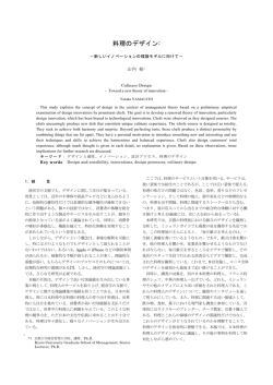
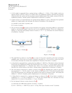
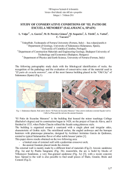
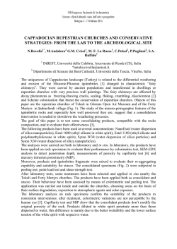
Seismic Behaviour of Prestressed Timber Columns under Bi-directional Loading
Asif Iqbal
Stefano Pampanin
Andy Buchanan
Department of Civil Engineering
University of Canterbury, Christchurch, New Zealand
Summary
Structural members made of laminated veneer lumber (LVL) in combination with unbonded posttensioning have recently been proposed, which makes it possible to design moment-resisting frames
with longer spans for multi-storey timber buildings. Moreover, prefabricated and prestressed timber
buildings can be designed to have enhanced re-centering and energy dissipation characteristics for
seismic resistance. The post-tensioning provides re-centering capacity while energy is dissipated
through the addition of special dissipating devices.
As part of a research program on timber structures, experimental and analytical studies have been
performed to investigate response of prestressed LVL columns under bi-directional seismic loading.
The results show excellent seismic performance, characterized by negligible damage of the structural
members and small residual deformations, even under the combined effect of loading in two
directions. Energy is dissipated mostly through yielding of external mild steel axial dissipators
connecting the column and the foundation, which can be easily removed and replaced after an
earthquake. Since post-tensioning can be economically performed on site, the system can be easily
implemented in multi-storey timber buildings.
1.
Introduction
Current seismic design philosophies for multi-storey buildings emphasize the importance of
designing ductile structural systems which undergo cycles of inelastic displacement during
earthquakes, resulting in some residual damage but no significant reduction in strength. Innovative
solutions have been developed under the U.S. PRESSS (PREcast Structural Seismic Systems)
programme coordinated by the University of California, San Diego [1] for the seismic design of
multi-storey precast concrete buildings. Such solutions are based on joints between pre-fabricated
elements with unbonded post-tensioning. As a result, efficient structural systems are obtained,
which can undergo large inelastic displacements, while limiting the damage to the structural system
and assuring full re-centring capability after the seismic event. A particularly efficient solution is
provided by the “hybrid” system [2] (Fig. 1) where an appropriate combination of self-centring
capacity (unbonded tendons plus axial load) and energy dissipation (mild steel dissipation devices)
leads to a “controlled rocking motion”, characterized by a “flag-shaped” hysteresis loop (Fig. 2).
The hybrid concept has been later implemented recently in timber structures [3]. For multi-storey
timber construction, LVL, fabricated from sheets of veneer glued into panels, is a suitable material
since it has a higher level of homogeneity and superior strength than rough sawn or glulam timber.
As part of a comprehensive research investigation for the development of innovative seismic
resisting systems for multi-storey timber construction, a number of different frame and wall systems
have been successfully tested [4] to [7] under uni-directional loading. In this contribution, timber
column-to-foundation subassembly has been tested in three dimensions.
In a practical building frame for multi-storey building, the columns, especially the corner columns,
are often subject to displacements in two directions simultaneously. Therefore, it was necessary to
test columns under bi-directional loading. A series of tests on cantilever timber columns connected
to steel foundation have been carried out. Both post-tensioned only solutions and hybrid solutions
with external dissipators are investigated for the specimen. Experimental results for the column-tofoundation subassembly under bidirectional cyclic quasi-static and pseudo-dynamic loading are
presented here. Further results of the experimental investigation are presented in Iqbal et al. [8].
The results are discussed here to evaluate the performance of the hybrid connections. Comparisons
have been made between results from the experiments and an analytical model.
Fig. 1 Hybrid connection and rocking motion
2.
Experimental Investigation
2.1
Properties of the Specimen Tested
Fig. 2 Flag-shaped hysteresis behaviour[9]
The LVL used for the column is Hy90 [10], manufactured in accordance with AS/NZS 4357. For
limit states design to the New Zealand Code NZS 3603 [11], Hy90 characteristic strengths are given
in Table 1.
Table 1. Material Properties of Hy90 LVL [9]
Modulus of Elasticity Parallel to Grain
E
9000
MPa
Bending Strength
f'b
35
MPa
Tension Strength Parallel to Grain
f't
19
MPa
Compression Strength Parallel to Grain
f'c
28
MPa
Compression Strength Perpendicular to Grain
f'p
10
MPa
The test specimen was originally designed as a timber bridge pier to have the moment capacity close
to that of a concrete bridge pier tested as part of a recent research project at University of
Canterbury, though it can be argued that it was representative of a column from a multi-storey timber
building. The column has been constructed to have a hollow section by gluing together four Hy90
sections from standard beam sections, each with a width of 360mm and thickness of 90mm (Fig. 3)
to make a column 450mm square. The hollow timber column could be upgraded to higher axial load
capacity for high-rise building structures by either making the cavity smaller or adding high strength
concrete infill while maintaining the unbonded post-tensioning arrangement. For commercial
production it will be preferable to use the arrangement shown in Fig. 3(b) for a large cavity or Fig.
3(c) for a small cavity, because both of these can be manufactured in a standard press.
Fig. 3: Column section details
2.2
Quasi-static Cyclic Testing
A series of tests were carried out on a single column with alternate arrangements subjected to bidirectional loading. There was no additional axial load applied, and the initial post-tensioning of
50% of tendon yield forces in the two tendons is designed to include some the axial force due to
gravity load. The bottom end of the timber column was placed directly on the steel foundation. No
attempt was made to increase the bearing strength of the bottom end of the column. The posttensioning tendons were anchored in a steel plate at the top of the column, and under the steel
foundation at the bottom. There was no other contact between the tendons and the column. The
cantilever column was horizontally loaded at the expected point of contra-flexure within a frame
system, i.e. the mid-level of the inter-storey height (Fig. 4a). The quasi-static loading protocol (Fig.
4b) consists of three cloverleaf-shaped cycles of increasing inter-storey drift, following the
acceptance criteria for moment-frames proposed by the ACI T1.1-01, ACI T1.1R-01 [12]. The load
was applied simultaneously from two orthogonal directions through hydraulic actuators (Fig. 4c).
Mild steel energy dissipators (Fig. 4d) were added to the column for the hybrid tests. The energy
dissipators consist of steel rods designed to yield in both tension and in compression. The 8mm
diameter rods are encased in steel tubes injected with epoxy to prevent buckling in compression. The
top end of each external dissipator was connected to an external steel case fixed to the LVL column,
and the bottom end was fixed to the steel foundation.
a)
X dir Drift (%)
-5
-2.5
0
2.5
5
5
2.5
0
0
Y d ir Drift (% )
Y Disp lacem en t (m m )
80
-2.5
-80
-80
-5
0
80
X Displacem ent (mm )
b)
d)
c)
Figure 4: a) Test setup; b) loading protocol; c) testing arrangement; d) dissipators
Figure 5: Details of specimens with designations
Two specimens with different levels of dissipation capacity (Fig. 5) were tested. First specimen to be
tested was specimen PT with unbonded post-tensioning only and no energy dissipators. The gray
lines on Fig. 6(a) and Fig. 6(b) illustrate the recorded values of lateral force vs. drift in the N-S and
E-W directions respectively. The tendon force vs. drift is shown in Fig. 7(a). It is visible that there is
some energy dissipation due to small inelastic deformations at the base of the column.
50
50
40
40
30
30
20
20
Load (kN)
Load (kN)
The hybrid solution was investigated using the Specimen H1 with two external dissipators placed at
each side along N-S direction, parallel to the plane of the tendons (Fig 5.). The black lines in Fig. 6
illustrate the lateral force vs. drift. The tendon force vs. drift is shown in Fig. 7(b). Significant
hysteretic dissipation is observed due to yielding of the energy dissipators. It is also important to
notice that greater dissipation is achieved in E-W direction, in the plane perpendicular to the tendons,
but it also tends to get some residual displacements because of smaller recentering forces from the
tendons in that plane. On the other hand, in the direction parallel to the plane of the tendons (N-S)
full recentering is achieved due to higher recentering forces from the tendons.
10
0
-4
-3
-2
-1
-10 0
1
2
-20
3
4
10
0
-4
-3
-2
-1
Hybrid
-30
PT only
-40
-10 0
1
2
3
-20
Hybrid
-30
PT only
4
-40
-50
-50
Drift (%)
Drift (%)
a)
b)
150
150
125
125
Load (kN)
Load (kN)
Fig. 6: Load-displacement plots of Specimens PT and H1 a) N-S direction; b) E-W direction
100
75
100
75
north tendon
north tendon
south tendon
south tendon
50
50
-4
-3
-2
-1
0
1
2
3
-4
4
-3
-2
-1
0
1
2
3
4
Drift (%)
Drift (%)
b)
a)
Fig. 7: Plots of tendon forces vs. drift of specimens a) PT and; b) H1
2.3
Pseudo-dynamic Testing
A series of pseudo-dynamic tests was carried out to simulate slow motion dynamic response of the
system subjected to earthquake input ground motions, in both post-tensioned only and hybrid
configurations. As part of the required information to solve the equation of motion of the SDOF
system within the pseudo-dynamic algorithm, an equivalent mass of 4500 kg was assumed,
corresponding to the expected gravity load (dead load plus a portion of the live load) for the tributary
area of a column within a single storey timber building. An equivalent viscous damping of 5%,
proportional to the initial stiffness was adopted.
The details of the earthquake ground motions used in the tests are given in Table 2. The test of
Specimen ST could not be continued for the whole duration of Landers accelerogram because the
maximum drift exceeded the displacement limit of the testing arrangement. Specimen H1 was
subjected to a 50% higher intensity of the same earthquake record in order to assure adequate
inelastic response and re-centring capability. The response is shown in Figure 8. In spite of the
higher intensity of the ground motion, maximum drift of Specimen H1 was less than that of
Specimen PT, due to the additional strength and dissipation contribution provided by the external
dissipators. A small residual displacement is observed in one direction due to the smaller out-ofplane recentering capacity of the two prestressing tendons.
Table 2. Characteristics of the adopted earthquake events
Event
Landers
Year Mw
Station
Duration,
sec
Scaling
Factor
Component
PGA, g
(scaled)
1992
Yermo
Fire
Station
44.0
2.2
360
0.334
270
0.245
Fortuna
Blvd
44.0
000
0.441
090
0.433
7.1
3.8
3
3
2
2
1
1
0
0
10
20
30
40
-1
Drift (% )
Drift (%)
Cape
1992
Mendocino
7.3
0
0
10
20
30
40
-1
-2
-2
-3
-3
Time (sec)
Time (sec)
b) E-W direction
a) N-S direction
3
3
2
2
1
1
0
0
10
20
30
40
Drift (%)
Drift (%)
Fig. 8 Time history plots of SpecimenH1 subject to Landers ground motion
0
0
-1
-1
-2
-2
10
20
30
40
-3
-3
Tim e (sec)
a) N-S direction
Time (sec)
a) E-W direction
Fig. 9 Time history plots of Specimen PT subject to Cape Mendocino ground motion
The Specimen PT was tested under Cape Mendocino accelerogram scaled to have intensity
comparable to the Landers earthquake (Table 2). Figure 9 shows the response of Specimen PT in
terms of drift time-history. As expected, the maximum drift in this case is greater than that of
Specimen H1, but full recentering is achieved despite partial asymmetry of the response.
3.
Analytical Study
It is necessary to develop analytical models of these solutions for practical structures. A preliminary
numerical model of one column-to-foundation system is described below. A simple analytical
approach based on section analysis concept and lumped plasticity model [13] is followed to calculate
the bi-directional behaviour of the column. Although the procedure was developed for precast
concrete structures, it has been found applicable to timber structures with minor adjustments [14].
The lumped plasticity model can be efficiently adopted for hybrid connections where the main
inelastic demand is accommodated within discrete critical sections (i.e. at the column-foundation
interface). Due to the opening and closing of a single crack at the interface, an infinite curvature is
developed at the critical section: therefore a moment-rotation relationship has to be preferred to a
traditional moment-curvature when characterizing the section behaviour. Rotational inelastic springs
in parallel, with appropriate hysteretic behaviour, are assigned to represent the inelastic action at the
column-foundation interface while elastic elements are used to represent the structural members. One
rotational spring is assigned a nonlinear elastic rule to represent the self-centring contribution, while
for the second spring a hysteresis rule representing the energy dissipation contribution is adopted.
MONOTONIC BEHAVIOUR
CYCLIC BEHAVIOUR
100
spring 1: multi-linear rule
(1)
50
150
M
tot
(t otal moment)
150
0
100
Hybrid connection
(1)
-50
100
50
Moment
M (unbonded P T st eel moment )
p
(2)
o
-100
-0.04
o
100
M (mild st eel moment )
s
50
o
o
0
0.02
0.04
spring 2: hysteresis rule
(2)
oo
0.01
Rotation
0.02
0.03
0.035
0
0
-50
50
MBA procedure
Linearized curves
0o
0
-0.02
-100
-150
-0.04
(
-0.02
0
0.02
0.04
-50
-100
-0.04
-0.02
0
0.02
0.04
Fig. 9 Calibration of springs referring to Monotonic Beam Analogy [13]
The calibration of the two rotational springs can be obtained by evaluating the monotonic momentrotation behaviour of each contribution, i.e. mild steel energy dissipation devices and post-tensioning
tendons, referring to the Monolithic Beam Analogy (MBA) procedure originally proposed by
Pampanin et al. [15] and subsequently refined by Palermo [16], which relies on member
compatibility in terms of displacements between a monolithic and a hybrid solution. As represented
in Fig. 9, each curve contribution obtained adopting the MBA can be linearized referring to the
fundamental performance levels, i.e. the decompression point, loss of linearity point, yielding,
serviceability and failure point. Fig. 9 summarizes the above mentioned calibration procedure
assuming a Ramberg-Osgood [17] hysteresis rule for the cyclic behavior of dissipator.
The computational scheme is implemented with the Ruaumoko [18] finite-element code. A threedimensional model of the column and its base connection was created to apply the bi-directional
loading. Bi-linear elastic elements have been used to model the post-tensioning tendons while
modified Takeda [19] hysteresis was used for the energy dissipators. Fig. 10 and Fig. 11 show the
comparison between the analytical and experimental results for post-tensioned only and hybrid
solutions respectively.
60
60
40
40
20
20
Load (kN)
Load (kN)
In general, satisfactory confirmation of the numerical procedure is established from the plots. The
dispersions from the experimental results can be attributed to a number of reasons. The column was
represented in the model by an elastic element. But in reality, as mentioned earlier, some inelastic
deformations take place at the base during the tests leading to greater energy dissipation. Although
shear keys were placed around the column base, small amounts of slippage were observed during the
tests, which are not accounted for in the numerical model. The timber also goes through strain
softening at higher drifts which results in forces lower than computed by the model. Further
analytical studies are currently ongoing to provide complete numerical predictions of such systems
and these factors can be incorporated in future analytical models currently under development.
0
-4
-3
-2
-1
0
1
2
3
4
0
-4
-3
-2
-1
-20
0
1
2
3
4
-20
Experimental
Analytical
-40
Experimental
-40
Analytical
-60
-60
Drift (%)
Drift (%)
a)
b)
60
60
40
40
20
20
Load (kN)
Load (kN)
Fig. 10 Comparative plots of PT-only specimen: a) N-S direction; b) E-W direction
0
-4
-3
-2
-1
0
1
2
3
4
0
-4
-3
-2
-1
0
1
2
3
4
-20
-20
Experimental
-40
Experimental
-40
Analytical
Drift (%)
Drift (%)
a)
Analytical
-60
-60
b)
Fig. 11 Comparative plots of Hybrid specimen: a) N-S direction; b) E-W direction
4.
Conclusions
The experimental results of cyclic quasi-static and pseudo-dynamic tests on LVL column-to
foundation connections under bi-directional quasi-static cyclic and pseudo-dynamic loading further
confirmed the applicability of multi-storey timber buildings with hybrid connections. The hybrid
systems showed a significantly greater level of energy dissipation compared with the post-tensioned
only solution. In all cases, considering different simulations of seismic loading, the tested systems
exhibited high levels of ductility, negligible residual deformations and no significant damage of the
structural elements. Analytical studies show good agreement between the experimental and
numerical results indicating that the behavior of the system in practical applications with can be
predicted with high level of confidence.
5.
Acknowledgements
The research in this paper is supported by FIDA (Forest Industries Development Agenda). The LVL
material was supplied by Carter Holt Harvey. The comments and suggestions from Dr. Alessandro
Palermo (Politecnico di Milano, Italy) and Dr. Massimo Fragiacomo (University of Sassari, Italy),
and technical support from Nigel Dixon and Gavin Keats are gratefully acknowledged.
6.
References
[1]
Priestley M.J.N., Sritharan S., Conley J.R. & Pampanin S., “Preliminary Results and
Conclusions from the PRESSS Five-story Precast Concrete Test-building”, PCI Journal, Vol.
44(6), 1999. pp. 42-67.
Stanton J.F., Stone W.C. and Cheok G.S., “A Hybrid Reinforced Precast Frame for Seismic
Regions”, PCI Journal, Vol. 42(2), 1997, pp. 20-32.
Palermo A., Pampanin S., Buchanan A. and Newcombe M., “Seismic Design of Multi-storey
Buildings using Laminated Veneer Lumber (LVL)”, Proc. NZSEE Conference, Wairakei, New
Zealand, 2005, CD-ROM.
Palermo A., Pampanin S., Fragiacomo M. Buchanan A. H. and Deam B. L., “Innovative
Seismic Solutions for Multi-storey LVL Timber Buildings”, Proc. of 9th World Conference on
Timber Engineering, Portland, Oregon, 2006, CD-ROM.
Palermo A., Pampanin S. and Buchanan A., ”Experimental Investigations on LVL Seismic
Resistant Wall and Frame Subassemblies”, Proc. of First European Conference on
Earthquake Engineering and Seismology, Geneva, Switzerland, 2006, CD-ROM.
Palermo A., Pampanin S., Fragiacomo M., Buchanan A.H., Deam B.L., and Pasticier L.,
“Quasi-static cyclic tests on seismic-resistant beam-to-column and column-to-foundation
subassemblies using LVL”, Proc. Australasian Conf on Mech. and Mat., Christchurch, 2006.
Smith T., Ludwig F., Pampanin S., Fragiacomo M., Buchanan A., Deam, B., and Palermo, A.,
“Seismic Response of Hybrid-LVL Coupled Walls under Quasi-static and Pseudo-dynamic
Testing”, Proc. NZSEE Conference, Palmerston North, New Zealand, 2007, CD-ROM.
Iqbal A., Pampanin S., and Buchanan A.H., “Experimental Study of Prestressed Timber
Columns under Bi-directional Seismic Loading”, Proc. NZSEE Conference, Wairakei, 2008.
NZS 3101, “Appendix B: Special provisions for the seismic design of ductile jointed precast
concrete structural systems”, Standards New Zealand, Wellington, New Zealand, 2006.
Futurebuild, “Engineered Building Products - Information for Design and Installation”,
Carter Holt Harvey Limited, Auckland, New Zealand, 2003.
NZS 3603, “Timber Structures Standard”, Standards New Zealand, Wellington, 1996.
ACI T1.1-01 and ACI T1.1R-01, Acceptance Criteria for Moment Frames Based on
Structural Testing (T1.1-01) and commentary (T1.1R-01), ACI Innovation Task group 1 and
Collaborators, 2006.
Palermo A., Pampanin S. and Carr A., “Efficiency of Simplified Alternative Modelling
Approaches to Predict the Seismic Response of Precast Concrete Hybrid Systems”, Proc. fib
Symposium “Keep Concrete Attractive”, Budapest, Hungary, 2005.
Newcombe M.P., “Seismic Design of Multi-storey Post-Tensioned Timber Buildings”,
Dissertation for Masters Degree in Earthquake Engineering, European School for Advanced
Studies in Reduction Of Seismic Risk (Rose School), Pavia, Italy, 2007.
Pampanin S., Priestley M.J.N., and Sritharan S., “Analytical Modelling of the Seismic
Behaviour of Precast Concrete Frames Designed with Ductile Connections”, Journal of
Earthquake Engineering, Vol. 5, No. 3, 2001, pp. 329-367.
Palermo A., “The Use of Controlled Rocking in the Seismic Design of Bridges”, Ph.D. thesis,
Dept. of Structural Engineering, Technical University of Milan, Italy, 2004.
Ramberg W. and Osgood. W.R., “Description of Stress-Strain Curves by Three Parameters”,
National Advisory Committee on Aeronautics, Technical Note 902, 1943.
Carr A.J., “RUAUMOKO Program for Inelastic Dynamic Analysis – Users Manual”,
Department of Civil Engineering, University of Canterbury, New Zealand, 2005.
Otani S., “Hysteresis Models of Reinforced Concrete for Earthquake Response Analysis”, J.
Faculty of Engineering, University of Tokyo, Tokyo, Vol. XXXVI, No. 2, 1981, pp 125-159.
[2]
[3]
[4]
[5]
[6]
[7]
[8]
[9]
[10]
[11]
[12]
[13]
[14]
[15]
[16]
[17]
[18]
[19]
© Copyright 2026 Paperzz