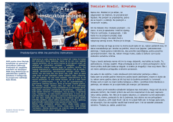
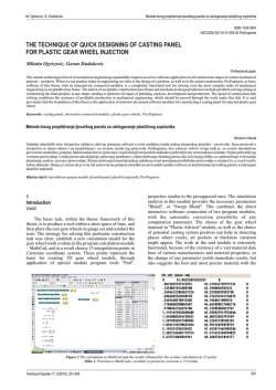
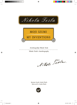
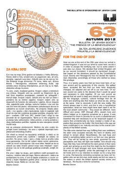
R. Čep, A. Janásek, B. Martinický, M. Sadílek
Ispitivanje trajnosti reznog alata keramičkih uložaka za tuljke automobilskih motora
ISSN 1330-3651
UDC/UDK 621.9.025:620.169.1
CUTTING TOOL LIFE TESTS OF CERAMIC INSERTS FOR CAR ENGINE SLEEVES
Robert Čep, Adam Janásek, Branislav Martinický, Marek Sadílek
Original scientific paper
This article is focused on the experimental determination of tool life tests for indexable ceramic cutting inserts. The set criterion of tool wear was VBBmax = 0,6
mm (in accordance with ISO 3685) or 30 pieces of machined sleeves. After at least one of the mentioned parameters was achieved, the tests were stopped and
evaluated. Two types of cutting material by Saint Gobain Advanced Ceramics s.r.o. Company – ZTA 7 NI and D 250 were tested. We monitored their tool life at
the same cutting parameters. The experiments were performed on machine tool – CHEMNITZ NILES N22. The machined material was the cast iron 25P
mainly used for car engines. Tool wear was monitored on every fifth machined sleeve. Microgeometry was measured after tool wear test on each fifth sleeve.
The aim was to determine the arithmetic tolerance of Ra profile, the greatest height of Rz profile and the external diameter D. The measurement was carried out
four times; arithmetic average was performed subsequently as it is shown in the tables.
Keywords: cutting tool tests, machining, surface roughness, tool wear
Ispitivanje trajnosti reznog alata keramičkih uložaka za tuljke automobilskih motora
Izvorni znanstveni članak
Ovaj članak je usredotočen na eksperimentalno određivanje trajnosti alata za indeksiranje keramičkih reznih uložaka. Postavljen je kriterij trošenja alata VBBmax
= 0,6 mm (sukladno ISO 3685) ili 30 komada obrađenih tuljaka. Kada je postignut barem jedan od ovih parametara, ispitivanje je zaustavljeno i procijenjeno.
Ispitivane su dvije vrste reznog materijala uz pomoć tvrtke Saint Gobain Advanced Ceramics s.r.o. – ZTA 7 NI i D 250. Pratili smo njihovu trajnost kod istih
parametara obrade. Eksperimenti su izvedeni na alatnom stroju – CHEMNITZ NILES N22. Obrađivani materijal bio je lijevano željeza 25P koje se koristi za
motore automobila. Trošenje alata praćeno je za svaki peti obrađeni tuljak. Mjerena je mikrogeometrija nakon ispitivanja trošenja alata na svakom petom tuljku.
Cilj je bio odrediti aritmetičku toleranciju Ra profila, najveću visinu Rz profila i vanjski promjer D. Mjerenje je provedeno četiri puta, aritmetička sredina je
izvedena naknadno i prikazana je u tablicama.
Ključne riječi: ispitivanje reznog alata, hrapavost površine, obrada rezanjem, trošenje alata
1
Introduction
Uvod
Tool wear tests belong to one of the basic parameters of
machining technology. The results of successful
application, which were obtained in practice, remarkable
increase of the quality of production and indirect affect on
the position of the enterprise in the sharp competition [3, 4].
That experimental determination of tool life can provide
additional information about cutting process in next tests
[5].
Roughness is a sum of surface imperfections with a
small distance. These phenomena arise from the production
or effect of production effect [6]. Surface defects not
assumed as the roughness are: random irregular geometry
(lines, crevices, etc.) and defects which arise by material
production [2].
2
Experimental part
Eksperimentalni dio
2.1
Machine tool
Alatni stroj
The machine tool CHEMNITZ NILLES N22
(Fig. 1) was used for test sample machining. The machine
tool has rigid structure and it provides a sufficient clamping
condition. Jaws have recessed cone with the same apical
angle as the cast iron sleeves.
Figure 1 Machine tool CHEMNITZ NILES N22
Slika 1. Alatni stroj CHEMNITZ NILES N22
2.2
Measuring machines
Mjerni strojevi
Ra and Rz values were evaluated on portable surface
roughness tester - Mitutoyo Surftest SJ-400. A wide range,
high-resolution detector and an ultra-straight drive unit
provide a class-leading accuracy. Cylinder surface
roughness is possible to be evaluated by the skid less
measurement and R-surface compensation functions.
An external diameter was determined by SOMET
micrometer (ČSN 25 1420; 50÷75 mm).
2.3
Machined material
Obrađeni materijal
As the machining material were used sleeves for car
Technical Gazette 18, 2(2011), 203-209
203
R. Čep, A. Janásek, B. Martinický, M. Sadílek
Cutting tool life tests of ceramic inserts for car engine sleeves
engines (Fig. 3), which were supplied by the contracting
authority. The class of material was 25P. Due to conical
shape of sleeves it was necessary to machine a cylindrical
surface and the same diameter. Supposing we had not done
it, a constant depth of cut ap would not have been maintained
during tests.
2.4
Used tools
Korišteni alati
A tool-holder CSSNR 2525 M12-K (Fig. 4) was used in
accordance with ISO 3685, with defined by an angle κr =
45°. Machining system is shown in (Fig. 5).
Figure 5 Machining system: 1 - tool-holder, 2 - chuck, 3 - workpiece
Slika 5. Obradni sustav: 1 - držač alata, 2 - glava, 3 - izradak
Figure 2 Portable Surface Roughness Tester
Mitutoyo Surftest SJ-400 [1]
Slika 2. Prijenosni mjerač hrapavosti površine
Mitutoyo Surftest SJ-400 [1]
a)
b)
Figure 3 Clamped sleeves:
before machining (a) and after machining (b)
Slika 3. Stegnuti tuljci: prije obrade (a) i nakon obrade (b)
Table 1 Chemical composition of the material
Tablica 1. Kemijski sastav materijala
C / % Si / % Mn / % P / %
2,8÷3,3 1,8÷2,5 0,6÷0,8 0,5÷0,8
S / % Ti / % Cu / %
< 0,1 0,03÷0,1 £ 0,8
2.5
Indexable cutting inserts
Rezne pločice
Two types of ceramic cutting inserts were tested in total
(the first type – 2 pieces and the second type – 4 pieces).
Only one cutting edge was tested on the plate of each type.
The cutting plates had the following marks:
- D 250_1
- ZTA_7_NI_2
- ZTA_7_NI_1
- D 250_2
- D 250_3
- D 250_4
2.6
Cutting parameters
Parametri rezanja
Cutting parameters were selected on the basis of
experience and consultations of the research team with a
contracting authority. The aim was to get as near as possible
to real operation conditions.
cutting speed vc = 500 m/min
!
feed f = 0,4 mm
!
cutting depth ap = 2 mm
!
number of chips per one sleeve: 4
!
machining length: 1st chip 61 mm, 2nd chip 60 mm, 3rd
!
chip 59 mm, 4th chip 58 mm
total machining length: 238 mm
!
dry machining.
!
Figure 4 The tool-holder with clamped ceramic cutting insert
Slika 4. Držač alata s pričvršćenim keramičkim uloškom
3
Experiments' evaluation
Procjena eksperimenata
The contracting authority supplied a semi-product of
204
Tehnički vjesnik 18, 2(2011), 203-209
R. Čep, A. Janásek, B. Martinický, M. Sadílek
Ispitivanje trajnosti reznog alata keramičkih uložaka za tuljke automobilskih motora
machined materials and two kinds of ceramic cutting
inserts. The criterion of tool wear was chosen VBBmax = 0,6
th
mm. If the 30 sleeve was machined and the critical value of
tool wear was not reached, the tests were stopped. The tool
life was determined as follows:
T =t× p
t=
Table 2 The number of machined pieces for individual cutting inserts
Tablica 2. Broj obrađenih komada za pojedinačne rezne uloške
D
ZTA_
ZTA_
D
D
D
250_1 7_NI_2 7_NI_1 250_2 250_3 250_4
Machined
pieces
27
26
15
30
30
30
(1)
4×l
,
n× f
(2)
where:
T – tool life, min
t – machining time, min
p – number of machined pieces, –
l – machining length, mm
n – spindle speed, 1/min
f – feed, mm.
Microgeometry was measured after the tool wear test th
th
th
th
th
on each 5 , 10 , 15 , 20 , 25 and 30th machined sleeve. The
aim of this experiment was to determine the arithmetic
tolerance of Ra profile, the greatest height of Rz profile and
the external diameter D.
Arithmetic tolerance of Ra profile, the greatest height of
Rz profile and the external diameter D are shown in the
following tables. Measurements were evaluated four times
– as shown in (Fig. 6). The arithmetic average was
calculated from these measurements.
Figure 7 The number of machined pieces for individual indexable
cutting inserts
Slika 7. Broj obrađenih komada za indeksirane rezne uloške
Table 3 Tool life for individual indexable cutting inserts
Tablica 3. Postojanost alata za pojedine rezne pločice
D
ZTA_
ZTA_
D
D
D
250_1 7_NI_2 7_NI_1 250_2 250_3 250_4
Tool life,
8,03 7,74 4,46 8,93 8,93 8,93
min
Figure 6 Measured surface – machined insert
Slika 6. Mjerena površina – obrađen uložak
3.1
Tool life and tool wear – individual cutting inserts
Vijek i trošenje alata – pojedinačni rezni ulošci
The number of machined pieces by individual ceramic
cutting inserts is shown in the following graph (Fig. 7). D
250 series of cutting inserts machined the maximum
number of 30 pieces except for D 250_1 insert. The D 250_1
insert probably reached this maximum as well. There was a
th
crack of sleeve (at machining the 27 sleeve) and it resulted
in cutting edge destruction. ZTA_7_NI inserts reached the
th
th
criteria of tool wear at 26 , respectively at 15 machined
sleeves. Fig. 8 shows the tool life of plates calculated
according to formula (1) and (2) in minutes.
Technical Gazette 18, 2(2011), 203-209
Figure 8 Tool life for individual indexable cutting inserts
Slika 8. Vijek alata za indeksirane rezne uloške
205
Cutting tool life tests of ceramic inserts for car engine sleeves
a) tool flank
a) tool flank
b) tool face
b) tool face
c) tip
c) tip
Figure 9 Tool wear – indexable cutting insert type D 250_1
Slika 9. Trošenje alata – rezna pločica tipa D 250_1
Figure 11 Tool wear – indexable cutting insert type ZTA_7_NI_1
Slika 11. Trošenje alata – rezna pločica tipa ZTA_7_NI_1
a) tool flank
a) tool flank
b) tool face
b) tool face
c) tip
c) tip
Figure 10 Tool wear – indexable cutting insert type ZTA_7_NI_2
Slika 10. Trošenje alata – rezna pločica tipa ZTA_7_NI_2
206
R. Čep, A. Janásek, B. Martinický, M. Sadílek
Figure 12 Tool wear – indexable cutting insert type D 250_2
Slika 12. Trošenje alata – rezna pločica tipa D 250_2
Tehnički vjesnik 18, 2(2011), 203-209
R. Čep, A. Janásek, B. Martinický, M. Sadílek
Ispitivanje trajnosti reznog alata keramičkih uložaka za tuljke automobilskih motora
Comment (Fig. 9):
- Tool face chipped from 17th piece;
- 28th piece – workpiece snapped and destroyed insert.
a) tool flank
b) tool face
Comment (Fig. 10):
th
- 25 piece – tool wear on lateral tool flank;
- Tool wear increases very slowly.
Comment (Fig. 11):
- Insert sparks almost from the beginning;
th
- 14 piece - significant deterioration of the surface and
significant sparks;
th
- 15 piece - unsatisfactory roughness - terminated.
Comment (Fig. 12):
- Calm cut without sparking;
- Tool wear is very small and almost not growing;
- Chipped tool face – at the end of tests.
c) tip
Figure 13 Tool wear – indexable cutting insert type D 250_3
Slika 13. Trošenje alata – rezna pločica tipa D 250_3
Comment (Fig. 13):
th
- 16 piece - inserts begin to sparkle slightly;
th
- 28 piece - spark ceased;
- Small tool wear.
Comment (Fig. 14):
th
- 8 piece - inserts begin to sparkle;
th
- 24 piece - spark is of low intensity;
- Small tool wear.
3.2
Surface roughness
Hrapavost površine
Table 4 Values of arithmetic tolerance of Ra profile
Tablica 4. Vrijednosti aritemetičke tolerancije Rz profila
c) tip
Figure 14 Tool wear – indexable cutting insert type D 250_4
Slika 14. Trošenje alata – rezna pločica tipa D 250_4
Technical Gazette 18, 2(2011), 203-209
20
1,82
4,26
25
1,61
3,03
27
1,98
30
-
not
measured
D 250_4
6,09
5,7
5,23
D 250_3
3,17
4,07
2,39
D 250_2
5
10
15
ZTA_
7_NI_1
ZTA_
7_NI_2
b) tool face
D 250_1
a) tool flank
Number
workpiece
Ra / μm
4,22
2,76
10,61
not
measured
not
measured
not
measured
5,68
4,72
5,06
6,58 5,94
2,33 5,77
1,69 4,70
4,15
1,78
4,03
3,54
2,28
3,70
-
-
-
4,37
1,97
2,02
The value of surface roughness (Ra) decreases with the
number of machined pieces of almost all sleeves. It is a
characteristic for the ceramic cutting tools. If we want to
achieve maximum performance, we have to "wear down"
lightly these inserts. If the plate achieved the maximum tool
life, roughness would begin to rise slightly. This could be
caused by increasing tool wear.
ZTA 7 NI_1 inserts caused sparking that increased with
the number of machined sleeves. This test was finished for
th
unsatisfactory roughness at the 15 piece as shown in the
graph.
207
Cutting tool life tests of ceramic inserts for car engine sleeves
R. Čep, A. Janásek, B. Martinický, M. Sadílek
Roughness is the most correlated with the Ra value.
This parameter is the most common in engineering practice
in the Czech Republic. Unfortunately, it is influenced by
unique extreme surface roughness.
Parameter of roughness of Rz profile decreases with
the number of machined pieces of almost all inserts with
slight deviations, as shown in the previous measurement. Rz
parameter nearly replicates Ra parameter.
3.3
External diameter
Vanjski promjer
Table 6 Values of the external diameter D
Tablica 6. Vrijednosti vanjskog promjera D
16,75
27
14,50
30
-
not
measured
D 250_4
10,20
D 250_3
25
D 250_2
19,85
ZTA_
7_NI_1
ZTA_
7_NI_1
12,80
D 250_4
ZTA_
7_NI_2
20
19,80
19,80
53,95
not
measured
not
measured
not
measured
D 250_3
D 250_1
28,50
26,50
25,10
D 250_2
Number
workpiece
20,33
20,20
17,60
5
73,56
73,51
73,49
73,50
73,58
73,47
10
73,56
73,55
73,64
73,60
73,64
73,51
15
73,72
73,59
73,70
73,69
73,63
73,83
73,72
73,64
73,86
73,79
73,90
73,88
73,89
73,96
0,38
0,31
0,49
20
Rz / μm
5
10
15
ZTA_
7_NI_2
Table 5 Values of the greatest height of Rz profile
Tablica 5. Vrijednosti najveće visine Rz profila
D 250_1
Figure 15 Arithmetic tolerance of Ra profile
Slika 15. Aritemetička tolerancija Ra profila
Number
workpiece
Ø D / mm
25
27
30
29,33 36,90 28,23
22,45 15,35 26,50
26,58 11,25 23,83
Δ
74,03
not
73,75
73,62
measured
not
73,81
73,71
measured
73,81
not
not
measured measured
0,25
0,20
0,534
22,70 11,48 20,15
21,68 15,73 18,63
-
-
-
27,53 14,20 14,43
Figure 17 External diameter D
Slika 17. Vanjski promjer D
Figure 16 The greatest height of Rz profile
Slika 16. Najveća visina Rz profila
208
The value of external diameter D growths with
increasing number of machined sleeves. This process is
caused by the tool wear. The tool wear was created
especially on lateral tool flank (edge) and on the tip which
was "burned". It changed a decrease in dimensional
accuracy (first and last piece did not have the same
diameter). The difference was in several tenths of
Tehnički vjesnik 18, 2(2011), 203-209
R. Čep, A. Janásek, B. Martinický, M. Sadílek
millimetres (see in Tab. 6). Abrasion and peeling off were
created at the tool face of inserts. This phenomenon should
not have any significant effect on dimensional accuracy.
Tool wear is caused by high thermal and mechanical load.
The tool is not able to perform its function (after a period) as
a result of this process. Tool wear arises from abrasive wear,
plastic deformation and brittle fracture.
4
Conclusion
Zaključak
The requirements are very high on the parameters of
surface integrity in engineering practice. Cutting speed is
being constantly increased. This leads to the CNC
machining; these machines can secure the optimal working
conditions so it is possible to produce products with the
finest precision.
ZTA 7 NI inserts did not reach the maximum number of
30 machined inserts. The reason was impaired surface
roughness in both cases. Tests were finished for
unsatisfactory surface. The cutting inserts reached the
prescribed criterion of tool wear (VBBmax).
D 250 inserts had significantly better results. Almost all
plates machined the maximum number of inserts at tool
wear (VBBmax) about 0,2 mm, except the first. The D 250_1
insert could reach this maximum as well. The sleeve
cracked (hollow in the casting) – the result was the
destruction of the cutting edge. We will need to focus more
on these parameters in other experiments – secondary edge,
tool tip and tool face. The tool wear arises on the secondary
edge and the tip. There is reduction of dimensional accuracy
as a consequence (first and last piece have not the same
diameter). The difference is in several tenths of millimetres.
Figures 15 and 16 show that the value of both roughness
parameters is lower after 30 pieces machined. Roughness
(Ra) is below 6,3. Roughness (Ra) gets even under 3,2 with
an increasing number of machined inserts – D 250 series.
This can be attributed to the properties of ceramics material
which must be "abrade" first and then its potential can be
fully realized.
D 250 inserts are suitable for cutting inserts made from
25P material at given cutting parameters and cutting
geometry. The whole machining was carried out in dry
(without using the liquid process) and it is environmentally
friendly.
Ispitivanje trajnosti reznog alata keramičkih uložaka za tuljke automobilskih motora
[5] Cep, R.; Ocenasova, L.; Novakova, J., Kouril, K.; Valicek, J.;
Barisic, B. Influence of Thermal and Mechanical Shocks to
Cutting Edge Tool Life. // Proceedings of World Academy of
Science, Engineering and Technology, 56, (2009) (August),
pp. 754-757. ISSN 2070-3740.
[6] Cebalo, R.; Stoić, A. Optimisation of the roughness of the
ground surface by diamond roller dressing. // Tehnical
gazzete. 9, 3-4 (2003), pp 3-8, ISSN 1330-3651.
[7] Jurkovic, Z.; Cukor, G.; Andrejcak, I. Improving the surface
roughness at longitudinal turning using the different
optimization methods // Tehnical Gazette. 17, 4 (2010), pp
397-402, ISSN 1330-3651.
Authors' addresses
Adrese autora
Robert Čep, Assoc. prof. Ing. PhD.
Adam Janásek, Ing.
Marek Sadílek, Ing., Ph.D.
VŠB - Technical University of Ostrava
Faculty of Mechanical Engineering
346 - Department of Machining and Assembly
17. listopadu 15/2172
708 33 Ostrava - Poruba
Czech Republic
+420 597323193
[email protected]
Branislav Martinický, Ing., PhD.
University of Žilina
Faculty of Mechanical Engineering
Department of Machining and Manufacturing Technology
Univerzitna 1
010 26 Zilina
Slovakia
5
References
Literatura
[1] www.mitutoyo-czech.cz [online]. 2009 [cit. 2011-01-08].
Mitutoyo SJ-400. <http://www.mitutoyo-czech.cz/cz/pdf/
SJ%20400-CZ.pdf>.
[2] Orlovsky, I.; Hatala, M. Sprinkle Drying Kiln Ceramic
Granulate Drying Characteristic and Experimental
Measurements of the Drying Process Parameters. // Tehnicki
Vjestnik - Technical Gazette, 16, 2(2009), 27-30. ISSN 13303651.
[3] Čep, R.; Neslušan, M.; Barišič, B. Chip Formation Analysis
During Hard Turning. // Strojarstvo, 50, 6(2008), 337 – 345.
ISSN 0562-1887.
[4] Neslušan, M.; Turek, S.; Brychta, J.; Čep, R.; Tabaček, M.
Experimentálne metódy v trieskovom obrábaní. Žilina : EDIS
Žilina, 2007. 343 p. ISBN 978–80–8070–711–8.
Technical Gazette 18, 2(2011), 203-209
209
© Copyright 2026 Paperzz