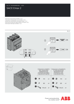
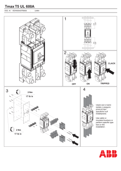
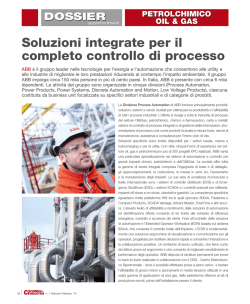
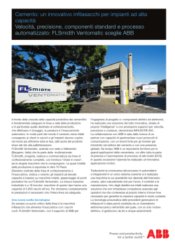
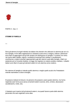
Doc. N.° 1SDH001000R0820 - L9324
SACE Emax 2
Parte fissa di interruttore estraibile - E2.2-E4.2-E6.2
Fixed part of withdrawable circuit-breaker - E2.2-E4.2-E6.2
Unterteil des ausfahrbaren Leistungsschalters - E2.2-E4.2-E6.2
Partie fixe de disjoncteur débrochable sur chariot - E2.2-E4.2-E6.2
Parte fija de interruptor extraíble - E2.2-E4.2-E6.2
E2.2-E4.2-E6.2
2
1
OK
2
OK
1
A
B
C
D
1
42
44
Q4
32
D1
34
Q3
24
Q2
14
C2 C12 C22
YO YC2 Q1
D2
C2
48
Rca
46
K2
Ne+
Ne-
W4
K51
27
K1
46
48
45
RTC
71
45
D2
YU YC
RTC YO2
41
31
C3
YC
73
74
D2
C12
C1
D1
78
C2
C1 C11 C21
YO
W3
72
D1
K51
C13
Ne-
C1
K51
Ne
77
YC
C12
C11
YO
76
YU
YO
C11
YO2
75
C21
C22
YC
79
22
YC2
Q/1
21
Q/2
12
Q/3
81
11
42
44
41
32
34
31
22
24
21
12
14
11
Q/4
C3 C13
Figure number of the diagram
K51
2
SACE Emax | ABB
Contact ready to close
71
Input of current sensor on the external
neutral
27
Ventilation operating mechanism
31 32
Auxiliary power supply and local bus
33 34
72 73 74
EKIPSupply
Module
Module
Module
Trip Unit I/O
Signalling modules
41 42 43
and/or Ekip synchro check
48
and/or Communication modules
51 ..
.. 58
and/or redundant communication
modules
61 ..
.. 66
Zone selectivity
26
25
Input of the residual-current protection
RC sensor
24
Ekip Measuring voltage sockets
20 21 22 23
Trip reset coil YR
14
Closing springs loading motor
13
Springs loaded position signalling
contact
12
U2
U1
38
98
04
K10
K9
36
96
K6
K5
35
95
94
74
K7
84
K4
K8
H4
01
02
H3
1
Q5..Q10 EKIP Signalling 4K
Q/6
Q/5
HC
K7
64
Q/7
K3
Q/8
02
04
01
92
94
91
82
84
81
72
74
71
62
64
61
52
54
51
54
HC
Q/9
K8
K3
O 01
Q/10
36
38
35
96
98
95
HC
O 02
S51
K9
K4
K51/SIGN
S33M/2
52
I 02
H1
U2
K10
K5
O 03
K51/SIGN
U1
92
I 03
H3
S33M/1
91
K6
O 04
K51/SIGN
F1
H2
I 04
K51/SIGN
H4
I 01
K51/SIGN
R1
81
11
H2
77 78
YR
YR
M
12
K51/SIGN
First closing coil
Second opening coil
Under-voltage coil
Input of the TRAFO star centre sensor
R2
13
K51/SIGN
75 76
L1 L2 L3
14
K51/SIGN
79
First opening coil
M
23
N L1L2L3
VN
V1
V2
V3
K51/MEAS
VN
20
Second closing coil
S51 S33
K51/MEAS
21
22
V1 Gzo Szc Gzi
24
K51/MEAS
26
Rct
Rca
Ge+
Ge-
82
25
Szi
Szo
Gzi
Gzo
Szc
H1
Rct
Rca
66
Rct Ge- Szo
K51
..
72
K51
K33
61
..
W..R
V2
K31
I 31
HC3
K51/COM
R2
K51/SIGN
K32
K34
Szi
I 32
Ge
K51/SIGN
..
58
Vn
K21
V3
K23
W..
71
H31
I 21
K51/SIGN
51
..
K51/COM
K22
HC
H32
K24
62
K51/SIGN
O 32
K51/SIGN
I 22
VS1
VS2
61
O 22
H21
O 31
43
K13
K51/SIGN
HC2
Vs
K11
I 11
51
K51/SIGN
W4
R1
K51/SIGN
H22
O 21
K51/SIGN
W3
KS2
O ORTACOMUNIC.
COMMUN. O ORT
H11
81
48
KS1
XSC
K14
K2
K51/SYNC
HC1
42
K51/SYNC
K12
I 12
K1
ALIM.AUS. +/L
AUX. SUPPLY -/N
O ORTACOMUNIC.
COMMUN. O ORT
RIDONDANTE
REDUNDANT
K51/SIGN
K51/SIGN
H12
O 12
K51/SIGN
O 11
41
Open/closed auxiliary contacts
of the circuit-breaker (first set)
K51/..
LOCAL BUS
31
32
33
34
n
Trip signalling contact
11
Ekip signalling 4K
2
Additional auxiliary contacts
of the circuit-breaker (second set)
1
2
A
21 Nm
185.87 lb·in
C
OK
D
B
NO
SACE Emax | ABB
3
Max O 3,3mm
Max O 0,13"
8mm
0.31"
2
1
2
0,5 2,5mm
20 AWG 14 AWG
8mm
0.31"
Max O 3,3mm
Max O 0,13"
0,5 1,5mm
2
20 AWG 16 AWG
4
Esempio di cablaggio per parte fissa
Wiring example for fixed part
Verdrahtungsbeispiel für Unterteil
Exemple de câblage pour partie fixe
Ejemplo de cableado para parte fija
2 "CLICK"
1
5
Inserzione ed estrazione degli interruttori in esecuzione estraibile
Connection and disconnection of withdrawable-type CBs
Einschieben und herausfahren der Leistungsschalter in ausfahrbarer Ausführung
Embrochage et débrochage des disjoncteurs en version débrochable sur chariot
Inserción y extracción de los interruptores en ejecución extraíble
L’interruttore si può manovrare soltanto se il pulsante
“PUSH BEFORE OPERATE” non è premuto, e cioè
soltanto quando l’interruttore è in una di queste tre posizioni.
Lo stato del CB deve essere Aperto, durante l'inserimento ed il sezionamento.
Ulteriori info in accordo al manuale.
The circuit breaker can operate only when the “PUSH
BEFORE OPERATE” button is not pressed, i.e. only
when the CB is set to one of the following three positions.
The state of the CB must be opened during insertion and disconnection.
More info according to the manual.
Das Schalten des Leistungsschalters ist nur dann möglich,
wenn die Taste “PUSH BEFORE OPERATE” nicht
gedrückt ist, d.h. wenn sich der Leistungsschalter in
einer dieser drei Stellungen befindet.
Der Zustand des CB muss beim Einführen und Schneid geöffnet werden.
Mehr Infos nach dem Handbuch.
Le disjoncteur ne peut être manoeuvré que si le bouton
“PUSH BEFORE OPERATE” n’est pas enfoncé, c’estàdire uniquement quand le disjoncteur est dans l’une
de ces trois positions.
L'état de la CB doit être ouvert lors de l'insertion et de coupe.
Plus d'infos selon le manuel.
El interruptor puede manipularse sólo si el botón “PUSH
BEFORE OPERATE” no ha sido pulsado; es decir, sólo
cuando el interruptor se encuentra en una de las
siguientes tres posiciones.
El estado del IA se debe abrir durante la inserción y corte.
Más información de acuerdo con el manual.
SACE Emax 2| ABB
DISCONNECT
TEST
CONNECT
6
7
3
2
1
3
2
8
2
1
3 OK!
SACE Emax | ABB
9
1
2
3
1
2
10
Posizione di estratto
Disconnected position
Trennstellung
Position de débroché
Posición de extraído
11
PUSH
SACE Emax | ABB
12
13
Non tenere premuto il pulsante durante la manovra
Do not hold the button down during the operation
Sie während des Manövers nicht halten Sie die Taste gedrückt
Ne pas maintenir le bouton enfoncé pendant la manœuvre
No mantenga presionado el botón durante la maniobra
1
2
14
Posizione test
Test position
Prüfstellung
Position de test
Posición de prueba
SACE Emax | ABB
15
Non tenere premuto il pulsante durante la manovra
Do not hold the button down during the operation
Sie während des Manövers nicht halten Sie die Taste gedrückt
Ne pas maintenir le bouton enfoncé pendant la manœuvre
No mantenga presionado el botón durante la maniobra
Posizione di inserito
Connected
Betriebsstellung
Position embroché
Posición de insertado
1
2
16
17
SACE Emax | ABB
18
=
=
OK
NO!
ATTENZIONE! Accertarsi che, durante l'estrazione della parte mobile, entrambe le guide parte fissa
eseguano la medesima corsa mantenendo la parte mobile parallela alla parte fissa.
WARNING! When withdrawing the moving part, make sure that both guides on the fixed part travel to the
same extent, thereby keeping the moving part parallel to the fixed part.
ACHTUNG! Sicherstellen, dass während des Herausfahrens des beweglichen Teils beiden Führungen des
festen Teils den gleichen Hub ausführen, damit das bewegliche Teil parallel zum festen Teil halten.
ATTENTION! Vérifier, pendant l'extraction de la partie mobile, que les deux glissières de la partie fixe
effectuent la même course en maintenant la partie mobile parallèle à la partie fixe.
¡ATENCIÓN! Verificar que, durante la extracción de la parte móvil, ambas guías de la parte fija efectúen la
misma carrera, manteniendo la parte móvil paralela a la parte fija.
SACE Emax | ABB
19
Example for E2.2 III IEC Lockable shutters
n°2 Ømax 8mm
n°2 Ømax 0.31"
20
Example for E2.2 III UL Lockable shutters
n°2 Ømax 8mm
n°2 Ømax 0.31"
For more information please contact:
ABB S.p.A.
ABB SACE Division
Via Pescaria, 5
24123 Bergamo - Italy
Phone: +39 035 395 111
© Copyright 2014 ABB. All rights reserved.
www.abb.com
© Copyright 2026 Paperzz