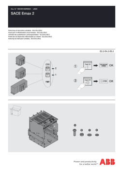
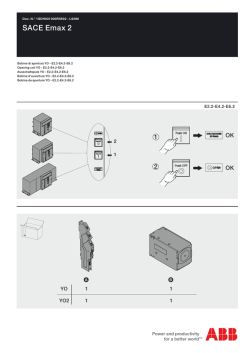
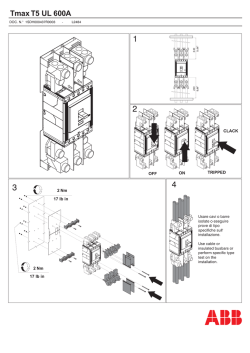
Doc. N.° 1SDH000999R0820 - L9324
SACE Emax 2
Parte fissa di interruttore estraibile - E1.2
Fixed part of withdrawable circuit-breaker - E1.2
Unterteil des ausfahrbaren Leistungsschalters - E1.2
Partie fixe de disjoncteur débrochable sur chariot - E1.2
Parte fija de interruptor extraíble - E1.2
E1.2
2
1
OK
2
OK
1
A
M6
x4
D
M8
x4
B
ø6
x4
E
ø8
x4
M6x30
x4
M8x25
x4
F
C
1
K51
Ne+
Ne-
27
H12
K51/SIGN
42
44
Q4
32
34
Q3
22
24
12
14
Q1
C2 C12
YO
YU YC
RTC YO2
D2
C3 C13
71
Input of current sensor on the
external neutral
27
W3
EKIP Supply
LOCAL BUS
Auxiliary power supply and Local Bus 31 32
23
SACE Emax | ABB
Module
Module
R1
R2
F1
S33M/1
U1
U2
S33M/2
S51
For more information see 1SPM000091
.. 58
and/or redundant
communication modules
61 ..
.. 66
36
38
35
96
98
95
Trip Unit I/O
Zone selectivity
26
Input of the TRAFO star centre sensor
25
Input of the residual-current
protection RC sensor
24
20 21 22 23
YR
12
51 ..
Trip reset coil YR
14
M
M
13
and/or Communication
modules
Ekip Measuring voltage
sockets
L1 L2 L3
14
48
Closing springs loading motor
13
S51 S33
N L1 L2 L3
YR
20
VN
V1
V2
V3
Rct Ge- Szo
K51/MEAS
VN
V1 Gzo Szc Gzi
K51/MEAS
21
22
V2
K51/MEAS
U2
24
Szi
Szo
Gzi
Gzo
Szc
26
Rct
Rca
Ge+
Ge-
U1
Rct
Rca
..
R2
K51
41 42 43
66
38
K51
K31
36
K33
W..R
98
I 31
61
..
K51/COM
K32
96
K34
K51/SIGN
HC3
25
I 32
K51/SIGN
58
Szi
H31
K23
Signalling modules
and/or Ekip synchro check
..
Ge
O 32
K51/SIGN
H32
K21
I 21
W..
Vn
K51/SIGN
K24
V3
I 22
51
..
K51/COM
K22
R1
K51/SIGN
35
H21
O 31
K51/SIGN
Contact ready to close
VS1
VS2
K13
HC2
43
W3
95
O 22
H22
O 21
K51/SIGN
73 74
KS2
Vs
K51/SIGN
HC1
K51/SIGN
72
77 78
48
KS1
XSC
K14
Second opening coil
Under-voltage coil
75 76
K51/SYNC
K51/SIGN
42
W4
K51/SYNC
K12
I 12
K2
COMMUN. O ORT
K51/SIGN
81
K1
ALIM. AUS. +/L
AUX. SUPPLY
-/N
COMMUN. O ORT
RIDONDANTE
REDUNDANT
41
O 12
31
32
Q2
41
K51
K51/..
48
71
46
46
48
45
Ne
D2
RTC
First closing coil
Rca
D1
K2
C2
First opening coil
K1
YC
73
74
D2
C3
W4
C2
K51
21
78
C12
C1
11
72
D1
C13
YO
n
Open/closed auxiliary contacts
of the circuit-breaker (first set)
C1 C11
YC
C1
K51
YC
77
YO
76
C12
YO2
75
YU
YO
Q/1
D1
Q/2
45
Q/3
81
Ne-
42
44
41
32
34
31
22
24
21
12
14
Q/4
31
Figure number of the diagram
Springs loaded position signalling
contact
12
Trip signalling contact
FLOOR MOUNTING
2
F
E
21 Nm
185.87 lb in
D
WALL MOUNTING
3
A
B
C
9 Nm
79.66 lb in
SACE Emax | ABB
4
Max O 3,3mm
Max O 0,13"
8mm
0.31"
2
2
0,5 2,5mm
1
8mm
0.31"
Max O 3,3mm
Max O 0,13"
0,5 1,5mm
2
5
2 "CLICK"
1
6
Inserzione ed estrazione degli interruttori in esecuzione estraibile
Connection and disconnection of withdrawable-type CBs
Einschieben und herausfahren der Leistungsschalter in ausfahrbarer Ausführung
Embrochage et débrochage des disjoncteurs en version débrochable sur chariot
Inserción y extracción de los interruptores en ejecución extraíble
DISCONNECT
TEST
CONNECT
SACE Emax 2 | ABB
7
8
Posizione di estratto
Disconnected position
Trennstellung
Position de débroché
Posición de extraído
9
SACE Emax | ABB
10
Non tenere premuto il pulsante durante la manovra
Do not hold the button down during the operation
1
Ne pas maintenir le bouton enfoncé pendant la manœuvre
No mantenga presionado el botón durante la maniobra
Posizione test
Test position
Prüfstellung
Position de test
Posición de prueba
2
3
Non tenere premuto il pulsante durante la manovra
Do not hold the button down during the operation
1
Ne pas maintenir le bouton enfoncé pendant la manœuvre
No mantenga presionado el botón durante la maniobra
Posizione di inserito
Connected
Betriebsstellung
Position embroché
Posición de insertado
2
12
SACE Emax | ABB
13
14
1
2
15
Example of Lockable Shutters for E1.2 Fixed part 3 poles IEC
n°2 Ømax 8mm
n°2 Ømax 0.31"
SACE Emax | ABB
16
Example of Lockable Shutters for E1.2 Fixed part 3 poles UL
n°2 Ømax 8mm
n°2 Ømax 0.31"
For more information please contact:
ABB S.p.A.
ABB SACE Division
Via Pescaria, 5
24123 Bergamo - Italy
Phone: +39 035 395 111
© Copyright 2014 ABB. All rights reserved.
www.abb.com
© Copyright 2026 Paperzz