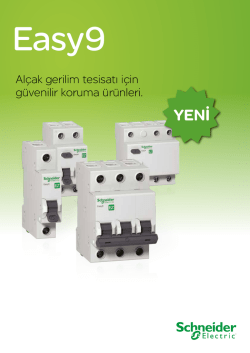
Ditec Smart Reset
0DT833
rev. 2014-06-13
Kılavuz türü kurulum, bakım, kullanım.
TR
Installation manual, maintenance, use.
EN
(Orijinal talimatral)
(Original instructions)
www.ditecentrematic.com
İçindekiler
Böl.
Konu Başlığı ....................................................................................................................... Sayfa.
1.
TEKNİK ÖZELLİKLER ................................................................................................................. 2
2. GENEL GÜVENLİK UYARILARI . ................................................................................................ 3
3. MEKANİK KURULUM
3.1 Geçiş aralığı kontrolleri............................................................................................................ 4
3.2 Dikey destek direklerinin sabitlenmesi..................................................................................... 4
3.3 Sarım şaftının kurulumu........................................................................................................... 4
3.4 Tahrik motorunun kurulumu (K22)............................................................................................ 4
3.5 SLEC (Lineer enkoder) güvenlik cihazının kurulumu.............................................................. 4
3.6 Örtünün konumlandırılması...................................................................................................... 4
3.7 Fotosellerin kurulumu (varsa).................................................................................................. 4
4. ELEKTRİK BAĞLANTILARI
4.1 Elektrik panosu........................................................................................................................ 5
4.2 Elektrik panosu / motor / emniyetler......................................................................................... 5
4.3 Emniyet fotoselleri.................................................................................................................... 5
5. ELEKTRONİK KUMANDA PANELİ
5.1 48E - bağlantılar....................................................................................................................... 6
5.2 47E (inverter) - bağlantılar..................................................................................................... 10
6.
KONTROLLER VE ÇALIŞTIRMA
6.1 SLEC (Lineer enkoder) güvenlik cihazının ayarlanması........................................................ 14
6.2 Örtü gerginliğinin ayarlanması............................................................................................... 14
7.
ARIZA ARAŞTIRMASI................................................................................................................ 15
8. BAKIM PLANI ............................................................................................................................ 16
1. GENEL GÜVENLİK UYARILARI
Bu kurulum kılavuzu sadece profesyonel personele yönelik olarak hazırlanmıştır.
Kurulum, elektrik bağlantıları ve ayarlar, Best Practice uygulamaları çerçevesinde ve yürürlükteki mevzuata uygun
olarak gerçekleştirilmelidir.
Ürünün kurulumuna başlamadan evvel talimatları dikkatle okuyunuz. Hatalı kurulum tehlikeli durumlara neden olabilir.
Ambalaj malzemeleri (plastik, polistiren vs.) doğada yok olmaz ve potansiyel tehlike kaynağı oluşturduğu için çocukların
erişebileceği yerlerde bırakılmamalıdır.
Kuruluma başlamadan evvel ürünün eksiksiz olduğunu kontrol ediniz. Ürünü patlayıcı ortam veya atmosferde kurmayınız:
yanıcı gaz veya dumanlar, emniyet açısından büyük tehlike oluşturur. Kapının kurulumuna geçmeden önce, ezme, kesme,
taşıma alanları ile genelde tehlike arz eden tüm bölgelerin muhafaza ve tecrit edilebilmesi için, gerekli olan tüm yapısal
değişiklikler gerçekleştirilmelidir.
Mevcut yapının gerekli sağlamlık ve denge özelliklerine sahip olduğunu kontrol ediniz. Emniyet cihazları (fotosel, hassas
kenarlar, acil durum durdurma tertibatları vs.) aşağıdaki hususlara dikkat edilerek kurulmalıdır: Yürürlükte bulunan mevzuat
ve direktifler, Best Practice kriterleri, kurulumun yapıldığı ortam, sistemin işleyiş mantığı ve motorlu kapılardan kaynaklanan
kuvvetler.
Güvenlik tertibatları, olası ezme, kesme, taşıma ve genelde tehlike eden alanlar ile kapı korumalıdır. Tehlikeli bölgeleri
belirtmek için yürürlükte olan yönergelerle belirlenen işaretleri kullanınız.
Her kurulum, kapının kimlik bilgilerini, görünür bir şekilde ihtiva etmelidir.
Elektrik bağlantısını gerçekleştirmeden önce, plakadaki verilerin elektrik dağıtım şebekesine ait olanlarla aynı
olduklarından emin olunuz. Besleme şebekesine, bağlantı teması açıklığı 3 mm veya yukarısı olan bir adet çok kutuplu
şalter veya devre kesici monte ediniz. Elektrik tesisatının yukarı elektrik akımında uygun bir diferansiyel şalter ve aşırı
akım emniyeti olması gerekmektedir. Kapıyı, yürürlülükteki güvenlik normlarına uygun şekilde döşenmiş olan bir topraklama
hattına bağlayınız. Kapı, güvenli ve düzgün çalıştırma için uygun olmayan parçalar ile takılırsa veya üreticinin izni dışında
herhangi bir değişiklik yapılırsa üretici hiçbir sorumluluk kabul etmez. Ürünlerin tamiri veya değiştirilmesi durumunda sadece
orijinal Entrematic Group AB yedek parçalar kullanılmalıdır. Kurulumu yapan kişi kullanıcıya motorize edilmiş olan kapının
otomatik, manuel ve acil durum işlevleriyle ilgili tüm bilgileri verecek ve kullanma talimatlarını teslim edecektir.
İsteğe bağlı aksesuar
C
Safety Confort
T
Safety Top
Tüm hakları saklıdır
Verilen bilgiler azami dikkat gösterilerek düzeltilmiş ve kontrol edilmiştir. Bununla birlikte, olası hatalar, ihmaller veya teknik
ya da grafiksel gereksinimler dolayısıyla yapılan yuvarlamalar için herhangi bir sorumluluk kabul etmemiz mümkün değildir.
0DT833 2014-06-13
-2-
TR
4
14
3
1
2
6
15
7
13
20
12
18
16
17
8
10
9
22
5
21
6
11
Ref.
1
2
3
4
5
6
7
8
9
10
11
19
7
Tanım
Yan kafalar
Kasa
Kasa kapağı
Sarım şaftı
SLEC (Lineer enkoder)
Polizenden yapılma üst bölüm kılavuzu
Polizenden yapılma alt bölüm kılavuzu
Kılavuz sabitleme desteği
Dik köşe parçası
Kılavuz desteği yayı
Kılavuz sabitleme vidası
Ref.
12
13
14
15
16
17
18
19
20
21
22
Tanım
Kolon kapağı
Tahrik motoru K22
Manuel manevra aygıtı
Manuel manevra çubuğu
Elektronik panosu
Fotosel LAB4
Fotosel 5FB
Polyester örtü
Şeffaf PVC pencereler
Dikey takviye şeritleri
Kum balastlı alt kenar
2. TEKNİK ÖZELLİKLER
ELEKTRİK PANOSU TRİFAZE (48E)
ELEKTRİK PANOSU 47E (INVERSEUR)
Besleme gerilimi ................................. 400 V, 50/60 Hz
Emiş ........................................................................ 6 A
Yardımcı kumandaların beslenmesi.................24V
Motor gücü.....................................................0,75 KW
Kumanda paneli koruma derecesi....................... IP 55
Çalışma sıcaklığı........................................ - 5 + 50 °C
Besleme gerilimi ................. 230 V monofaze 50/60 Hz
Emiş ...................................................................... 16 A
Yardımcı kumandaların beslenmesi.................24V
Motor gücü..................................................... 0,75 KW
Kumanda paneli koruma derecesi....................... IP 55
Çalışma sıcaklığı........................................ - 5 + 50 °C
Kabloların emiş uzunluğu ve konumu göz önünde bulundurularak belirlenen hat iletkenlerinin doğru şekilde
boyutlandırılması.
-3-
0DT833 2014-06-13
3. YAPI MEKANİK
Sayfa 22 - 23'teki mekanik kurulumla ilgili şekillere bakınız (ortadaki sayfa çıkarılacaktır)
3.1 Geçiş aralığı kontrolleri (fig.1).
• Aralığın boyutlarını kontrol ediniz ve tedarik edilen kapının ölçülerine uygun olduğundan emin olunuz; kurulum sırasında
gerekli olabilecek payları da göz önünde bulundurmayı unutmayınız.
• Mevcut olası aksamların, yapının montajı açısından engel teşkil etmediklerinden emin olunuz.
• Destek düzlemlerinin seviyelerini kontrol ediniz; gerektiğinde uygun kalınlıklar kullanarak seviyeye getiriniz.
• Aralığın yapısının sağlamlığını kontrol ediniz: Etriye ve takozlar aracılığı ile sağlam ankrajın tesis edilmesi şarttır. Sağlamlığın
yetersiz olması veya bu yönde kuşkuların bulunması durumunda, kendini taşıyabilme özelliğine sahip uygun metal bir
yapının oluşturulması şarttır.
3.2 Dikey destek direklerinin sabitlenmesi (fig.2).
• Dikey destek direklerini ayarlayınız ve (A) noktalarına tespit ediniz. Takozların boyları: M8.
• Montaj sonrasında örtünün yana doğru gerilmesini sağlamak için yuvarlak deliğin merkez eksenini (A) deliniz.
• Diyagonal ölçüleri kontrol ederek, montajın dik olarak gerçekleştirildiğinden emin olunuz.
3.3 Sarım şaftının kurulumu (fig.3).
• Kalıpları (B) kullanarak kirişteki tespit deliklerin konumlarını işaretleyiniz.
• Forklift veya diğer bir kaldıracı kullanmak sureti ile traversi dikkatlice kaldırınız; kaldırma işlemi sırasında düşmemesine
özen gösteriniz ve örtüyü olası zararlardan koruyunuz.
• Kenar uç kısımları (C ve D), dikey direklerin dış kısmına hizalayınız
• Yan uç kısımlarını, (E) deliklerini kullanmak sureti ile uygun ve güvenli bir şekilde tespit ediniz. Takozların boyları: M8.
Mevcut olan sabitleme yuvalarının tümünü kullanarak, yan plakaları 8 vida ile sabitleyiniz. Metre başına düşen
yaklaşık ağırlık 40 kg/m'dir.
merdane karteri ve muhafazası; PL > 4000 kapıları söz konusu olduğunda, kirişin orta kısmını tespit etmeniz önerilir
(estetik olmayan bel vermelerin önlenmesi için).
3.4 Tahrik motorunun kurulumu (K22) (fig.4).
Manuel manevra (öngörülmüş ise); res. 4'teki talimatları uygulayınız
Emniyet miktrosviçini ilgili şemasına uygun olarak bağlayınız ve doğru çalıştığından emin olunuz: Mikrosviç, manuel
kullanımın başlaması ile motorun dönmesine engel olmalıdır.
• (F) anahtarını, sarım şaftının üzerinde bulunan (G) yuvasına yerleştiriniz (res.5).
• Tahrik motorunu şafta geçiriniz.
• (H) takozunu kullanmak sureti ile tahrik motorunu baş kısma tespit ediniz.
• Motoru birlikte verilen M8 x 55 vida (J) vasıtasıyla şafta sabitleyiniz.
3.5 SLEC (Lineer enkoder) güvenlik cihazının kurulumu
• SLEC cihazı, (res.6)'de gösterildiği gibi, esnek kapının sol tarafındaki sürgülü ray üzerine monte edilmelidir, bağlanın
(bölüm 5)'de gösterildiği üzere.
3.6 Örtünün konumlandırılması
• Kılavuzların üst kısmına (I) yaklaşınız (res.6).
• Örtünün (L) her bir tespit elemanını ilgili kılavuza geçiriniz, gerekirse, daha uzun olan ilk vidayı (K) çıkarınız
• Örtüyü, alt kenarı örtünün geri sarım açıklığının yarım metre altında yer alacak şekilde açınız (res.8).
3.6 Fotosellerin kurulumu (varsa) (res.9).
• Muhafazaları dikey destek direklerine monte ediniz ve yerden azami yüksekliğinin 200 mm olmasına dikkat ediniz.
• Fotoselleri bağlayınız (res.12)'de gösterildiği üzere
0DT833 2014-06-13
-4-
TR
4. ELEKTRİK BAĞLANTILARI
4.1 Elektrik panosu
• Önceden kablolanmış bağlantı tabları ile kabloları kaba yerleştiriniz ve kartlara bağlantıları yapınız (fig.10). Kabloları
kanallara yerleştiriniz ve motorun üzerinde bulunan konektörleri bağlayınız (res.11).
4.2 Elektrik panosu bağlantıları / motor / emniyetler
• Resim 12'de, tedarik edilen kablolar ile kapıya yerleşimleri gösterilmektedir; her bir kablo, üzerinde bulunan yapışkanlı bir
etikete yazılı koda sahiptir.
4.3 Emniyet fotoselleri
• Bağlantıları, (res.12)'de gösterildiği üzere gerçekleştiriniz.
• Elektronik pano bağlantılarını, şemalara göre tesis ediniz.
10
11
12
FC
4328
4327
8132
8132
7825A
8457
7979
7978
SLEC
PH ≤ 4000mm (A935C)
PH ≥ 4000mm (A935L)
0 1
0 1
Rx
Siyah
Mavi
Tx
C
Siyah
Mavi
Turuncu
Kırmızı
C
Tx
Rx
T
T
Tx
8265A
Rx
Mavi
Siyah
Kahverengi
0 6 1
Mavi
Kahverengi
0 1
8265B
Kabloların emiş uzunluğu ve konumu göz önünde bulundurularak belirlenen hat iletkenlerinin doğru şekilde
boyutlandırılması.
-5-
0DT833 2014-06-13
48E
5.1 ELEKTRİK PANOSU 48E - Bağlantılar
GIRIŞLER
Komut
İşlev
Tanım
1
2
N.A Otomatik kapanma
Kontağın sürekli kapalı olması, otomatik kapanmayı devreye sokar.
1
3
N.A Açılma
DIP1=ON ile kontağın kapanması açılma manevrasını aktive eder.
Kademeli
1
4
N.A Kapanma
1
6
N.K
41
8
1
DIP1= OFF ile kontağın kapatılması aşağıdaki sıraya göre işleyen bir
açılma veya kapanma manevrasını aktive eder: açma-stop-kapatmaaçma.
NOT: Otomatik kapanmanın devrede olması halinde stop kalıcı değildir
ve süresi TC tarafından ayarlanır.
Kontağın kapanması kapanma manevrasını aktive eder.
Ters yön emniyeti
Emniyet kontağının açılması kapanma etabı esnasında hareketin tersinin
(tekrar açılma) uygulanmasına neden olur.
N.K
Ters yön emniyeti
Emniyet kontağının açılması kapanma etabı esnasında hareketin tersinin
(tekrar açılma) uygulanmasına neden olur.
9
N.K
Stop
Emniyet kontağının açılması hareketin durmasına neden olur.
1
9
N.A Darbesiz komut
Emniyet kontağının daimi olarak açılması, darbesiz komutun
çalıştırılmasına imkan verir.
Bu durumda (1-3/1-20) açılma ve (1-4) kapanma kumandaları sadece
basılı tutuldukları sürece çalışır, bırakıldıkları zaman otomasyon durur.
Emniyetler, kademeli komut ve otomatik kapanma işlevi devre dışı olur.
1
20
N.A Kısmi açılma
Kontağın kapanması, süresi RP trimeri ile ayarlanmış olan bir kısmi açılma
manevrasını tetikler.
Otomasyon durur haldeyken kısmi açılma kumandası durmadan önceki
manevranın tersini uygular.
0
11
N.K
Devre kesme
Devre kesici kontağının açılması, kapanma hareketini durdurur.
0
12
N.K
Devre açma
Devre kesici kontağının açılması, açılma hareketini durdurur.
0
17
N.A Devre fotosel
By-pass fotosel
Darbesiz komutla çalışma
Darbeli komutla çalışma
17 14 12 11 0 0 0 1 1 2 3 4 6 8 9 20 41
17 14 12 11 0 0 0 1 1 2 3 4 6 8 9 20 41
ÇIKIŞLAR
Çıkış
Değer
Tanım
1
0
+
–
24 V = / 0,5 A
Aksesuarların beslemesi.
Otomasyon durumunu gösteren lambalar dahil, harici aksesuarların beslenme
çıkışı için.
0
14
24 V = / 50 W
(2 A)
Yanıp sönme (LAMPH).
Açma ve kapama manevraları sırasında aktive olur.
-Y
+Z
200 V = / 0,2 A
Kapının hareketi esnasında çıkış aktive olur.
UWV
M
3~
0DT833 2014-06-13
400 V~ / 4 A
Trifaz motor.
NOT: Motor dönüş yönünün hareket yönüne uymaması durumunda, U - W
fazlarının yerini değiştiriniz
-6-
TR
48E
17
0
Beyaz
12
11
0
Siyah
Mavi
B
By-pass fotosel
A
C
F.C Açılma
F4
EL07L
0000000000000
F.C Kapanma
SE
Kahverengi
FU
K22
www.ditec.it
Stop
Kahverengi
U
V
M
3~
J7
Siyah
COM
Fren
W
Gri
EO
SO
Kırmızı
RP TC
EL07PW2
0000000000000
Beyaz
1
3
9
4
LDV
LDR
20
PRG
140
Sarı/Yeşil
U W V
ON
ON
1 2 3 4 5 6
- LK +
12
17
IN
SA
Y Z X
11
POWER
17 14 12 11 0 0 0 1 1 2 3 4 6 8 9 20 41
4328
4327
NIO
7979
Kahverengi
Beyaz
Siyah
Mavi
8457
Beyaz
Pembe
Kırmızı
Kahverengi
Mavi
Gri
Sarı
Yeşil
Beyaz
Kırmızı
L3
L2
L1
F5
Siyah
Kırmızı
Mavi
turuncu
Beyaz
Kahverengi
1-9 kapatınız:
Darbeli komutla
çalışma
F1
F2
F3
7825A
LAB4
0 1 6 1
ON
0 1
1 2 3 4
C T
SLEC
Mavi
Siyah
Kahverengi
8265B
Siyah
Mavi
0 1
R1
8265A
Kırmızı
Mavi
Sarı
Yeşil
Pembe
Beyaz
Kahverengi
Gri
0 1 9 41 FC FA OUT
PWR SA
0 6 1
5FB
Tx
Rx
Power 400V~
0 1
Siyah
turuncu
Mavi
0 1 6 1
8132
Siyah
Mavi
0 1
8132
Mavi
Kahverengi
8132
Siyah
Mavi
turuncu
Kırmızı
8132
0 6 1
Rx
Tx
C
T
7978
-7-
0DT833 2014-06-13
Ayarlar VE Sinyaller
48E
Trimer
TC
RP
Tanım
0s
30 s
0s
30 s
Otomatik kapanma zamanının ayarlanması. 0 ila 30 saniye arası
NOT: Stop komutunun aktive edilmesinden sonra, 1-9 kontağı tekrar kapanırken, otomatik kapanma
işlevi sadece bir tam açılma, kısmi açılma veya kademeli açılma komutundan sonra aktive olur.
Motorun kısmi açılımı ayarı. 0 ila 30 saniye arası.
Ditec Smart Reset için
Dip-switch
şu şekilde
konumlandırınız:
Dip-switch
ON
1 2 3 4 5 6
Köprüler
Tanım
OFF
ON
DIP 1
Çalıştırma kumandası 1-3.
DIP 2
DIP 3
Otomatik kapanma zamanının
yenilenmesi.
Çalışma öncesi 3 saniye sabit
süre yanan lamba.
DIP 4
Uygulama tipi.
Kullanmayınız. Esnek kapı.
DIP 5
Dİnamik kapanma freni.
Kullanmayınız. Devrede.
DIP 6
Çift hızlı.
Devre dışı.
Tanım
Kademeli.
Açılma.
Kullanmayınız. % 100
Açılmada
devre dışı.
Hem açılmada hem
kapanmada devrede.
Kullanmayınız.
OFF
ON
SO
Ters yön emniyetinin Otomasyon durur haldeyken, 41-8 Otomasyon durur haldeyken, 41-8
çalışması
bağlantısının açık olması durumunda, açma bağlantısının açık olması durumunda,
manevrasının başlatılması mümkündür.
her türlü manevra engellenir.
EO
Elektro fren.
LED
Kullanmayınız.
Normal.
Açık
Yanıp sönme
GÜÇ
24 V= besleme mevcut.
SA
- STOP işlevinin, PT4 tuş takımından (varsa) çalıştırıldığını
bildirir.
- SOFA1 düzeneği kullanıldığında, emniyet testinin başarısız
En az bir emniyet kontağının açık
olduğunu belirtir (41 no'lu uç).
olduğunu belirtir. ( 6 - 8 - 9 )
- Çalıştırma esnasında LED ışığı yanıp sönerek yapılan
manevraların sayısını belirtir:
her bir hızlı yanıp sönme = 10000 manevra
her bir yavaş yanıp sönme = 100000 manevra
IN
Her bir komut ve kısa anahtar ile
köprü değişiminde yanar.
/
11
Kapama devre kesici kontağının
kullanımda, 0-11'in açık olduğunu gösterir.
/
12
Kapama devre kesici kontağının
kullanımda, 0-12'in açık olduğunu gösterir.
/
17
0-17 hat sonu devre kesici kontağının açık
olduğunu gösterir. (By-pass fotosel)
/
/
Tuş
LED
ON
Açılma manevrasını aktive eder.
Yanan yeşil led ışığı, 24 V= beslemesinin bulunduğuna işaret eder.
Kısmı açılma manevrasını aktive eder.
STOP işlevini aktive eder kapatır.
Kırmızı led, STOP'un aktive edildiğine işaret eder.
Yanıp sönen kırmızı led, emniyetlerin aktif hale getirildiklerine işaret eder.
Kapanma manevrasını aktive eder.
0DT833 2014-06-13
-8-
TR
48E
SE
F4
FU
EL07L
0000000000000
www.ditec.it
ON
COM
EO
SO
RP TC
EL07PW2
0000000000000
J7
PRG
1
3
9
4
LDV
LDR
20
U W V
ON
ON
1 2 3 4 5 6
- LK +
12
17
IN
SA
POWER
NIO
17 14 12 11 0 0 0 1 1 2 3 4 6 8 9 20 41
Y Z X
11
L3
L2
L1
F5
SİGORTALAR
ID
Değerler
Boyut
Devre
F1 - F2 - F3
8A - 500V
10.3 x 38
Üç Fazlı Hat
F4
3.15A - 230V
5 x 20
Trasformatör
F5
2.5A - 500V
5 x 30
Dİnamik freni + Fren
F1
F2
F3
Devre kesicilerin ayarlanması
1 Düğmelere basarak kapıyı hareket ettiriniz ve doğru yöne hareket
ettiğinden emin olunuz ve gerektiğinde, fazların sırasını değiştirerek
kabloları kullanarak U - W.
C
2. Örtüyü kapama konumuna getiriniz.
B
A
3 Bir tornavida ile “C” kamını, ilgili mikrosviçi hareket ettirene kadar
çeviriniz.
A
4 Benzer şekilde açma devre kesicisini ayarlayınız: Örtüyü, açık kapı konumuna
getiriniz ve “A” kamını ayarlayınız.
5 LAB4 fotosellerinin bulunması durumunda, baypas devre kesicisini
(“B” kamı), mikrosviçin yerden 200 mm mesafede devreye girmesini
sağlayacak şekilde ayarlayınız.
6 Otomasyonu çalıştırmak sureti ile ayarları kontrol ediniz ve gerektiğince
“ince” ayar yapınız.
-9-
B
C
200 mm
0DT833 2014-06-13
5.2 47E ELEKTRONİK KUMANDA PANELİ (INVERTER) - Bağlantılar
47E
GIRIŞLER
İşlev
Komut
Tanım
1
2
N.A Otomatik kapanma
Kontağın sürekli kapalı olması, otomatik kapanmayı devreye sokar.
1
3
N.A Açılma
Kontağın kapanması açılma manevrasını aktive eder.
1
4
N.A Kapanma
Kontağın kapanması kapanma manevrasını aktive eder.
41
40
1
8
1
Ters yön emniyeti
Emniyet kontağının açılması kapanma etabı esnasında hareketin tersinin
(tekrar açılma) uygulanmasına neden olur.
N.K
Ters yön emniyeti
Emniyet kontağının açılması kapanma etabı esnasında hareketin tersinin
(tekrar açılma) uygulanmasına neden olur.
9
N.K
Stop
Emniyet kontağının açılması hareketin durmasına neden olur.
1
9
N.A Darbesiz komut
Emniyet kontağının daimi olarak açılması, darbesiz komutun çalıştırılmasına
imkan verir.
Bu durumda (1-3/1-20) açılma ve (1-4) kapanma kumandaları sadece
basılı tutuldukları sürece çalışır, bırakıldıkları zaman otomasyon durur.
Emniyetler, kademeli komut ve otomatik kapanma işlevi devre dışı olur.
1
20
N.A Kısmi açılma
Kontağın kapanması, süresi RP trimeri ile ayarlanmış olan bir kısmi açılma
manevrasını tetikler.
1
11
N.K
Devre kesme
Devre kesici kontağının açılması, kapanma hareketini durdurur.
1
12
N.K
Devre kesici
yavaşlama
Devre kesici kontağının açılması, açılma sırasında yavaşlamayı tetikler.
1
13
N.K
Devre açma
Devre kesici kontağının açılması, açılma hareketini durdurur.
N.K
ÇIKIŞLAR
Çıkış
Değer
+
-
1
0
LAMP
24 V = / 0,5 A
230 V~ / 50 W
RF
100Ω 32w
+F
Aksesuarların beslemesi.
Otomasyon durumunu gösteren lambalar dahil, harici aksesuarların beslenme
çıkışı için.
Yanıp Söner (LAMP).
Açma ve kapama manevraları sırasında aktive olur.
RF fren direncinin devreye girmesi.
Direnç her manevrada devreye girer.
CNT
-F
Tanım
200 V = / 0,2 A
Motor elektro freni.
Çıkış, hem açılma hem de kapanma hareketinin tümü boyunca aktif haldedir.
UWV
M
3~
0DT833 2014-06-13
230 V~ / 6 A
Trifaz motor.
- 10 -
47E
TR
Ditec Smart Reset kapısının üzerindeki J2 köprüsünü daima kesiniz
K22
Kahverengi
12
Beyaz
13
11
0
Siyah
Mavi
B
A
C
CNT
F.C Yavaşlama
17
F.C Açılma
1
140
Sarı/Yeşil
Siyah
U
V
Fren
M
3~
GND
W
Gri
16
F.C Kapanma
Stop
Kahverengi
+F -F U V W
U24
13
Beyaz
J2
OFF
T3
T2
9
4328
1 11 12 13
8
7
6
5
4
3
2
1 DL
41 40 20 9
8
4
3
2
1
1
0 LAMP
230 V 50/60 Hz
230 V ~
Mavi
Siyah
Kahverengi
Beyaz
7979
8457
1-9 kapatınız:
Darbeli komutla
çalışma
Pembe
Beyaz
Yeşil
Gri
Sarı
Mavi
Kahverengi
Kırmızı
Siyah
Mavi
Kırmızı
Turuncu
Beyaz
Kahverengi
7825A
8132
8132
PWR SA
C T
0 1 8 1
5FB
Rx
Tx
0 1
LAB4
0 1 8 1
0 40 1
Tx
SLEC
T
Siyah
Mavi
Turuncu
Kırmızı
Siyah
Mavi
Mavi
Siyah
Kahverengi
Siyah
Mavi
Mavi
Kahverengi
0 1
1 2 3 4
8132
0 1
8265B
R1
ON
0 8 1
8265A
0 1 9 41 FC FA OUT
8132
Siyah
Turuncu
Mavi
0 1
Kırmızı
Mavi
Sarı
Yeşil
Pembe
Beyaz
Kahverengi
Gri
4327
J1
10
F2
T4
14
T1
11
F1
T5
1 2 3 4
15
N
T6
12
ON
Kırmızı
L
Rx
C
7978
- 11 -
0DT833 2014-06-13
Ayarlar VE Sinyaller
47E
Trimer
Tanım
T1
0s
30 s
Otomatik kapanma zamanının ayarlanması. 0 ila 30 saniye arası.
T2
0s
10 s
Kısmi açılmanın ayarlanması. 0 ila 10 saniye arası.
0
MAX
0
MAX
0
MAX
0
MAX
T3
T4
T5
T6
Açılma hızının ayarlanması.
Kapanma hızının ayarlanması.
Açılma sırasında yavaşlamanın ayarlanması.
Kapanma sırasında yavaşlamanın ayarlanması.
Dip-switch
Tanım
DIP 1
Trimer aracılığı ile ayarlamaya
imkan sağlar
Devre dışı.
Devrede.
DIP 2
Açılma öncesi yanıp sönme
Devre dışı.
Devrede.
DIP 3
Gelecekteki Kullanım
Kullanmayınız.
Kullanmayınız.
DIP 4
Gelecekteki Kullanım
Kullanmayınız.
Kullanmayınız.
Fren Beslemesi
Fren 200 vcc
J2
LED
Input
DL1
(2)
DL2
OFF
LED
Input
Otomatik kapanma
DL10
(12)
F.C Yavaşlama
(3)
Açılma
DL11
(11)
F.C Kapanma
DL3
(4)
Kapanma
DL12
Yanıp sönme
DL4
(9)
Stop
DL13
RUN OK
DL5
(20)
Kısmi Açılma
DL14
Hata
DL6
(40)
Bar güvenliği
DL15
Otomatik test
Stop düğmesi
DL16
Fren
DL17
Manevra sayacı
DL7
Açık
ON
DL8
(8)
Kapanma sırasında emniyet
DL9
(13)
F.C Açılma
Tuş
Açık
LED
ON
Açılma manevrasını aktive eder.
Yanan yeşil led ışığı, 24 V= beslemesinin bulunduğuna işaret eder.
Kısmı açılma manevrasını aktive eder.
STOP işlevini aktive eder kapatır.
Kırmızı led, STOP'un aktive edildiğine işaret eder.
Yanıp sönen kırmızı led, emniyetlerin aktif hale getirildiklerine işaret eder.
Kapanma manevrasını aktive eder.
0DT833 2014-06-13
- 12 -
47E
TR
Ditec Smart Reset kapısının üzerindeki J2 köprüsünü daima kesiniz
CNT
17
+F -F U V W
16
ON
1
GND
U24
13
J2
OFF
J1
10
F2
T4
14
T3
T2
T1
11
F1
T5
1 2 3 4
15
N
T6
12
ON
L
9
1 11 12 13
8
7
6
5
4
3
2
1 DL
41 40 20 9
8
4
3
2
1
1
0 LAMP
230 V 50/60 Hz
SİGORTALAR
ID
Değerler
Boyut
Devre
F1 - F2
12A - 500V
10.3 x 38
Tek Fazlı Hat
Devre kesicilerin ayarlanması
C
1. Yavaşlama rampalarını sıfıra ayarlayınız. (T5 - T6)
B
A
2. Tahrik motoru üzerindeki (C) devre kesicisini, kapını kapanma noktasından
200/300 mm mesafede durmasını sağlayacak şekilde ayarlayınız.
3. (A) açma devre kesicisini açılma noktasına ayarlayınız.
A
4. (B) yavaşlama devre kesicisini, açılma mesafesinin yaklaşık ¾'ünde devreye
girecek şekilde ayarlayınız.
B
5. Açılma ve kapanma (T4) hızlarını trimer (T3) aracılığı ile ayarlayınız.
6. Durmanın efektif kapalı ve açık konumlarında gerçekleşmesini sağlamak için,
açma (T5) ve kapama (T6) yavaşlama rampalarının trimerlerini ayarlayınız.
¾
C
300
ARIZA ARAŞTIRMASI
KUMANDA
SORUN
DOĞRULAMA
Ör tünün herhangi bir Ör tü ve motor hareket • Elektrik panosu testi başarısız (yeşil led 13 sönük ve kırmızı
konumunda, herhangi etmiyor
14 yanık halde)
bir kumanda
Açılma kumandası
Il motor zorlanarak hareket • J2 köprüsünün kesiltmiş olup olmadığını kontrol ediniz (fren
ediyor veya ayarlı hıza
aktive olmuyor)
ulaşmıyor
• Manevra sırasında ana elektrik voltajının sabit kaldığını
kontrol ediniz
• Trimer açılma hızını düşürünüz (T3)
K a p a m a m a n e v r a s ı Motor yavaşlama rampasını • Kapama devre kesicisinin (C) zeminden yaklaşık 300 mm'ye
esnasında
gerçekleştirmiyor
ayarlanması
• Yavaşlama rampasının T6 trimeri vasıtasıyla ayarlanması
NOT: Genel arıza-teşhis için ayrıca syf. 15'e bakınız
- 13 -
0DT833 2014-06-13
6. ayarlamaları
6.1 SLEC (Lineer enkoder) güvenlik cihazının ayarlanması
Trimer
R1
MAX
LED
SA
ON
1 2 3 4
47E için
Dip - switch
şu şekilde
konumlandırınız:
ON
1 2 3 4
MIN
Engel hassasiyet ayarı.
Yanıyor / Yanıp sönüyor
PWR
48E için
Dip - switch
şu şekilde
konumlandırınız:
Tanım
Sönük
Besleme var
Besleme yok
• Başlatma
• Engele müdahale
• Test devam ediyor
• Test başarısız / Alarm
Engelsiz
normal çalışma.
Dip switch
Tanım
DIP 1
fonksiyon rüzgar
geçirmezlik
OFF
ON
Devre dışı
Devrede
DIP 2
Devre kesici
FC'nin
kapanmasından
sonra engel
algılanması
Devre dışı
Devrede (sadece İNVERTER'e
sahip elektronik
paneller)
DIP 3
Hassasiyet
ölçeği
YÜKSEK
DÜŞÜK
(kapılar hızlı kapa- (kapılar yavaş
nıyor)
kapanıyor)
DIP 4
Devre kesici
polaritesi
0 = Devre kesici
ortak noktası
(elektronik paneller
48-49-51)
1 = Devre kesici
ortak noktası
(elektronik paneller
47E)
6.2 Örtü gerginliğinin ayarlanması (fig.13)
• Kapıyı kapatınız.
• Dikey direklerin konumuna müdahale ederek örtünün gerginliğini ayarlayınız. Yer değiştirme iki direk üzerinde simetrik
olmalıdır. Montajın ayarlama bakımından doğru geometride olduğundan emin olunuz.
• Optimum ayarlama, polizen kılavuzlar çelik destekler üzerine dayalı halde, ancak yaylar sıkıştırma dengesinde iken
gerçekleştirilir.
Kılavuzları Vazelin sprey, yedek parça kodu 5VSGP (Wurth makale 0893060) yağlayınız
13
0DT833 2014-06-13
- 14 -
TR
7. ARIZA ARAŞTIRMASI
TEHLIKE
Elektronik cihazların içerisinde gerçekleştiren her işlem ve çalışma öncesinde, elektrik besleme hattının
çıkarılmış olduğundan emin olunuz.
DIKKAT
Aşağıdaki talimatlar yalnızca kalifiye ve yetkili personele yöneliktir. Açık şekilde belirtilmemiş olsalar
bile, özel kanunlara ve standartlara daima uyulmalıdır.
Tamir veya değiştirme işlemlerinde daima orijinal Entrematic Group AB yedek parçalarını kullanınız.
KUMANDA
SORUN
DOĞRULAMA
Ör tünün herhangi bir Örtü ve motor hareket • Şebeke beslemesi veya F1, F2, F3 sigortaları
konumunda, herhangi etmiyor
• STOP aktif halde (Tuş takımındaki “Stop” ledi sabit şekilde
bir kumanda
yanık halde)
• Motor yanlış kelepçelere bağlanmış ve/veya Dip-switch yanlış
konumda (bkz syf. 8)
• Açma ve kapama devre kesicileri (A ve C) aynı anda aktif halde
(led 11 ve 12 yanık halde)
• Motor termik korumada (led 11 ve 12 yanık halde)
• Manuel manevra emniyet mikro-sivici aktif halde (led 11 ve 12
yanık halde)
• Güç aygıtlarından biri arızalı (Elektrik panosu, motor, motor
bağlantı kablosu)
M ot o r t e r s r ot asyon • Besleme hattının iki fazının konumunu tersine çeviriniz
yönünde dönüyor
Örtü kapalı halde açılma Motor hareket etmiyor
kumandası
• Açılma kumandası doğru bağlanmamış veya arızalı (kumanda
aktive edildiğinde IN ledi yanmıyor)
• SO köprüsü kapalı iken emniyet aktive edilmiş (Stop düğmesinin
ledi yanıp söner halde ve SA ledi sabit şekilde yanık halde)
• Açılma devre kesicisi (A) aktif halde (12 ledi yanık halde)
• Kapanma kumandası daima aktive edilmiş halde veya kısa
devre (IN ledi daima yanık halde)
Örtü açık halde kapanma Motor hareket etmiyor
kumandası
• Kapanma kumandası doğru bağlanmamış veya arızalı
(kumanda aktive edildiğinde IN ledi yanmıyor)
• Emniyet aktive edilmiş (Stop düğmesinin ledi yanıp söner halde
ve SA ledi sabit şekilde yanık halde)
• Kapanma devre kesicisi (C) aktif halde (11 ledi yanık halde)
• Açılma kumandası daima aktive edilmiş halde veya kısa devre
(IN ledi daima yanık halde)
• Emniyet otomatik testi başarısız (tuş takımındaki Stop ledi
sönük halde ve SA ledi yanıp söner halde)
Bir manevra esnasında Motor durmuyor
Stop aktivasyonu
• Stop kumandası çalışmıyor veya doğru bağlanmamış (tuş
takımındaki Stop ledi yanmıyor ve SA ledi yanıp sönmüyor)
Motor durmakta gecikiyor • Motor freni aşınmış veya arızalı
Kapanma esnasında bir Kapının hareketi tersine • Emniyet aygıtı arızalı veya doğru bağlanmamış (tuş takımındaki
emniyetin aktive edilmesi çevrilmiyor
Stop ledi yanıp sönmüyor ve SA ledi yanmıyor)
Kapı hareketi ters yönde • 17 girişi kapalı (17 ledi sönük halde)
işlemiyor, ya da sadece • Kam B iyi ayarlanmamış (LED 17 yanmıyor veya hatalı
pozisyonda yanıyor)
h a r e ke t h a t t ı n ı n b i r
kısmında ters yönde işliyor
Örtü açık iken otomatik Kapı TC ile ayarlanmış • Otomatik kapanmanın devreye alınması doğru şekilde
kapanma aktif halde
süre sonrasında otomatik
gerçekleştirilmiyor (bağlantı 1-2)
olarak kapanmıyor
• Açılma kumandası daima aktive edilmiş halde veya kısa devre
(IN ledi daima yanık halde)
• Emniyet otomatik testi başarısız (tuş takımındaki Stop ledi
sönük halde ve SA ledi yanıp söner halde)
Bir manevra esnasında
Ö r tü d ev r e ke sic i ye • Devre kesici kontağı kısa devre (led 11 veya led 12 daima
ulaşınca durmuyor
sönük halde)
• Devre kesicide mekanik arıza (led 11 veya led 12 daima sönük
halde)
• Frende aşınma veya arıza (led 11 veya led 12 yanık halde)
Ö r t ü d ev r e ke s i c i ye • DIP-anahtarı 5 OFF konumunda
ulaşınca düzgün olarak • F5 sigortası atmış
durmuyor
NOT: 47E inverterli panoda özel arıza-teşhis için ayrıca syf. 13'e bakınız
- 15 -
0DT833 2014-06-13
8. BAKIM (6 ayda bir)
Yürürlülükte bulunan ulusal mevzuat ve ürün belgelerine uygun olarak, düzenli kontrollerin Entrematic Group AB tarafından
eğitilen ve tescil edilen teknik elemanlar tarafından yapılması şarttır. Bakım faaliyetlerinin aralığı, yürürlülükte bulunan ulusal
mevzuat ve ürün belgelerine uygun olmalıdır.
Güvenlik tertibatları
• SLEC (Lineer enkoder) aygıtının düzgün çalıştığını kontrol ediniz
• Güvenlik fotosellerinin düzgün çalıştığını kontrol ediniz
Yan kılavuzlar
• Yan kılavuzların aşınıp aşınmadığını kontrol ediniz
Kılavuzları Vazelin sprey, yedek parça kodu 5VSGP (Wurth makale 0893060) yağlayınız
Tespit / Montaj
• Dikey direklerin birleştirme vidalarını üst traversle sıkınız
• Kapının menteşeye ankrajını kontrol ediniz
Motorizasyon
• Motorun doğru şekilde tespit edildiğini kontrol ediniz
• Devre kesicinin çalıştığını ve kamların hizalı olduklarını kontrol ediniz
• Fren diskinde aşınma olup olmadığını kontrol ediniz. Gerekiyorsa diski değiştiriniz
Sarım şaftı
• Rulman desteklerinin tespit edildiğini kontrol ediniz
• Rulman desteklerini yağlayınız
8.1 Bakım planı
Aşağıda yer alan tabloda, önleyici bakım işlemleri sırasında parçaların değiştirilme sıklığı, çalışma ayı cinsinden verilmiştir.
Tanım
Kod
6DODGF
5M
22337
28106
V8144BP48
28125
6GLSLEC
Devre kesici grubu
Devre kesici (mikro sviç)
Fren diski
Polizenden yapılma üst kılavuz
Polizenden yapılma alt kılavuz
Kılavuz dengeleme yayı
Lens grubu ve boşluk SLEC
<10
Low Traffic
Ayda
36
48
36
36
48
36
36
Döngü / saat
<30
Medium Traffic
Ayda
24
36
24
24
36
24
24
>30
High Traffic
Ayda
12
24
12
12
24
12
12
Kirli ortam
(1)
12
24
12
12
24
12
12
(1) Kirli veya tozlu ortam, 0°C’ye yakın veya 35°C’den yüksek çalışma sıcaklığı, belirtilen maksimum sınırı %20 geçen rüzgar basıncı durumu.
ÖRTÜNÜN GERİ TAKILMASI
L
K
I
• Kılavuzların (I) üst kısmını dış kısımdan tutup kaldırarak yaklaştırınız.
• Örtünün (L) her bir tespit elemanını ilgili kılavuza geçiriniz, gerekirse, daha uzun olan ilk vidayı (K) çıkarınız.
• Örtüyü, alt kenar örtü giriş açıklığının yarım metre altında olacak şekilde çözünüz.
0DT833 2014-06-13
- 16 -
TR
KULLANIM VE BAKIM KILAVUZU
GENEL EMNİYET UYARILARI
İşbu kılavuz ürünün tamamlayıcı bir parçası olup, kullanıcıya teslim edilmelidir. İşbu belge muhafaza edilmeli ve
tesisin olası devri halinde yeni kullanıcılara teslim edilmelidir. Bahse konu otomasyon türü bir “dikey hareketli
kapı” olup, sadece tasarlanmış olduğu amaçlar çerçevesinde kullanılmalıdır. Diğer her tür kullanım yersiz ve
tehlikelidir. Entrematic Group AB, hatalı, meşru olmayan veya kusurlu kullanımdan kaynaklanan zarar ile ilgili
sorumluluk kabul etmez.
KULLANIM TEDBİRLERİ
• Hareket halindeyken, kapının hareket menzilinin içine girmeyiniz.
• Arıza veya hatalı çalışma halinde, ana şalteri kapatınız. Bakım, ayar ve tamir işlemleri, sadece eğitimli ve
yetkili personel tarafından yapılmalıdır.
• Her bir otomasyon sistemi "kurulum ve bakım kılavuzu" ile donatılmış olup, periyodik bakıma dair planı ihtiva
etmektedir; bu bağlamda, özellikle tüm emniyet tertibatlarının kontrol edilmesi tavsiye edilir.
TUŞLAR
• Komple açma: Kapıyı sonuna kadar açar. Hareketin ayarı, devre kesici mikrosviçler aracılığı ile yapılır.
• Kısmi açılma: Kapıyı, RP trimeri tarafından zamana göre ayarlanmış noktaya kadar açar.
• STOP: Kapının anında durmasını sağlar.
KESİNİZ VE KULLANICIYA VERİNİZ
• Kapanma: Kapıyı sonuna kadar kapar. Hareketin ayarı, devre kesici mikrosviçler aracılığı ile yapılır.
OPSİYONEL DS - MANUEL MANEVRA
• Elektrik kesintisi veya arıza söz konusu olduğunda, örtüyü elle kaldırmak için, şekilde gösterildiği üzere örtüyü
kapı açık konumuna kadar kaldırınız.
Kapının normal çalışması
sırasında süspansiyon halkasının
manuel manevra çubuğunu asılı
şekilde bırakmayınız. Duvara
montaj için uygun klipsleri
kullanınız.
Kapatma
Açar
Yükleyici:
Entrematic Group AB
Lodjursgatan 10
SE-261 44, Landskrona
Sweden
www.ditecentrematic.com
- 17 -
0DT833 2014-06-13
8. BAKIM (6 ayda bir)
Yürürlülükte bulunan ulusal mevzuat ve ürün belgelerine uygun olarak, düzenli kontrollerin Entrematic Group AB tarafından
eğitilen ve tescil edilen teknik elemanlar tarafından yapılması şarttır. Bakım faaliyetlerinin aralığı, yürürlülükte bulunan ulusal
mevzuat ve ürün belgelerine uygun olmalıdır.
Güvenlik tertibatları
• SLEC (Lineer enkoder) aygıtının düzgün çalıştığını kontrol ediniz
• Güvenlik fotosellerinin düzgün çalıştığını kontrol ediniz
Yan kılavuzlar
• Yan kılavuzların aşınıp aşınmadığını kontrol ediniz
Kılavuzları Vazelin sprey, yedek parça kodu 5VSGP (Wurth makale 0893060) yağlayınız
Tespit / Montaj
• Dikey direklerin birleştirme vidalarını üst traversle sıkınız
• Kapının menteşeye ankrajını kontrol ediniz
Motorizasyon
• Motorun doğru şekilde tespit edildiğini kontrol ediniz
• Devre kesicinin çalıştığını ve kamların hizalı olduklarını kontrol ediniz
• Fren diskinde aşınma olup olmadığını kontrol ediniz. Gerekiyorsa diski değiştiriniz
Sarım şaftı
• Rulman desteklerinin tespit edildiğini kontrol ediniz
• Rulman desteklerini yağlayınız
8.1 Bakım planı
Aşağıda yer alan tabloda, önleyici bakım işlemleri sırasında parçaların değiştirilme sıklığı, çalışma ayı cinsinden verilmiştir.
Tanım
Devre kesici grubu
Devre kesici (mikro sviç)
Fren diski
Polizenden yapılma üst kılavuz
Polizenden yapılma alt kılavuz
Kılavuz dengeleme yayı
Lens grubu ve boşluk SLEC
Kod
6DODGF
5M
22337
28106
V8144BP48
28125
6GLSLEC
<10
Low Traffic
Ayda
36
48
36
36
48
36
36
Döngü / saat
<30
Medium Traffic
Ayda
24
36
24
24
36
24
24
>30
High Traffic
Ayda
12
24
12
12
24
12
12
Ay cinsinden
sıklık Döngü/
saat
(1)
12
24
12
12
24
12
12
(1) Kirli veya tozlu ortam, 0°C’ye yakın veya 35°C’den yüksek çalışma sıcaklığı, belirtilen maksimum sınırı %20 geçen rüzgar basıncı durumu.
Tarih
0DT833 2014-06-13
Devir sayacı
İmza
Tarih
- 18 -
Devir sayacı
İmza
TR
KULLANMA TALİMATLARI
Servis sınıfı: 4 (günde 300 devir ile minimum 5 yıl kullanım)
Kullanım: YOĞUN (yoğun kullanımlı sanayi tipi ve ticari tip girişler için)
• Servis sınıfı, kullanım süresi ve ardıl devir sayısı değerleri yaklaşık değerlerdir. Ortalama kullanım koşullarında istatistiksel
olarak belirlenmiş olup her durum için kesinlik gösteremez. Ürünün olağan dışı bakıma ihtiyaç duymaksızın çalıştığı dönemle
ilgilidir.
• Her otomatik giriş şunlar gibi değişken öğeler gösterir: otomatik giriş kapısının veya kapının bileşen parçalarının (bunlara
otomasyon da dahildir) gerek dayanıklılık süresini gerekse çalışma kalitesini önemli ölçüde değiştirebilecek sürtünmeler,
dengelemeler ve çevre koşulları. Her montaj esnasında uygun güvenlik faktörlerinin uygulanması kurulumcunun
sorumluluğundadır.
Uygunluk Beyanı
Aşağıda imzası bulunan bizler:
Entrematic Group AB
Lodjursgatan 10
SE-261 44 Landskrona
İsveç
her türlü sorumluluğu üstlenerek aşağıda adı/açıklaması Performans Beyanında ve ürün etiketinde belirtilen performans
seviyesi ve ürün ile birlikte verilen kurulum kitapçığında belirtilen elektrik motoruna sahip cihazın:
Smart RESET
Karşı ağırlığı bulunmayan hızlı katlanır kapı
aşağıdaki direktiflere uygun olduğunu beyan ederiz direktif:
2006/42/EC
2004/108/EC
Makina Direktifi (MD)
Elektromanyetik uyumluluk direktifi (EMCD)
Uyumlaştırılmış Avrupa Standartları
EN 13241-1
EN 61000-6-2
EN 61000-6-3
EN 60335-1
EN 60204-1
Uygulanan diğer standart ve teknik şartnameler:
EN 60335-2-103
Aşağıdaki onaylanmış kuruluş (tam adresi için Entrematic Group AB ile irtibata geçiniz) ilgideki cihaz Tipi ile ilgili test sertifikası
yayınlamıştır:
CSI Spa Sicil. - N° 0497
Sertifika No.: DE/3382/09
Üretim süreci cihazın teknik dosyaya uygunluğunu garanti etmektedir.
Üretim süreci üçüncü kişiler tarafından düzenli olarak kontrol edilmektedir.
Teknik dosya sorumlusu:
Marco Pietro Zini
Entrematic Group AB
Lodjursgatan 10
SE-261 44 Landskrona
İsveç
Yer
Landskrona
E-mail: [email protected]
Tarih
2013-07-01
İmza
Marco Pietro Zini
- 19 -
Görevi
Entrance Automation şirketi Başkanı
0DT833 2014-06-13
0DT833 2014-06-13
- 20 -
TR
BİLEŞENLER LİSTESİ
Referans
Tanım
Miktar
A
Sol Kolon
1
B
Sağ Kolon
1
C
Sol Kapak
1
D
Sağ Kapak
1
E
Sarım şaftı
1
F
Motor K22
1
G
Elektrik panosu
1
H
Aksesuar kutusu
1
F
E
C
A
D
G
H
B
- 21 -
0DT833 2014-06-13
MEKANİK KURULUM ÇİZİMLERİ
1
330
LT = (PL + 380)
620
200 330
*250 180
PH
530
max. 200
150
PH
HT = (PH + 530)
200
LAB4ASR
LAB4ASRY
PL
100
60
360
100
3
E
B
C
D
5
F
H
J
G
6
MECHANICAL INSTALLATION DRAWINGS
2
X=Y± 10mm
X
A
A
Y
PL
4
12
11
0
STOP
U
V
W
M4x8
Ø9
DS
7
C NO
9
8
L
X
K
I
~ 0,5 m
MAX
200 mm
C
EN Packing List
Reference
Description
Quantity
A
Left column
1
B
Right column
1
C
Left Cover
1
D
Right Cover
1
E
Transom with rolled curtain
1
F
K22 Motor
1
G
Control unit
1
H
Hardware box
1
F
E
C
A
D
G
B
0DT833 2014-06-13
- 24 -
H
- 25 -
0DT833 2014-06-13
CONTENTS
Chap.
Topic . .................................................................................................................................... Page
1. 2.
3. 4.
5.
6.
7.
8.
GENERAL SAFETY PRECAUTIONS ........................................................................................ 26
TECHNICAL CHARACTERISTICS ............................................................................................ 27
MECHANICAL INSTALLATION
3.1 Checking the opening............................................................................................................ 28
3.2 Fitting the uprights................................................................................................................. 28
3.3 Installation of the rolling shaft................................................................................................ 28
3.4 Gearmotor installation (K22).................................................................................................. 28
3.5 Installation of the Safety Linear Encoder (SLEC).................................................................. 28
3.6 Positioning the curtain............................................................................................................ 28
3.7 Installing the photocells (when foreseen)............................................................................... 28
Electric connections
4.1 Control panel.......................................................................................................................... 29
4.2 Connecting the control panel / automation............................................................................ 29
4.3 Safety photocells.................................................................................................................... 29
ELECTRONIC CONTROL PANEL
5.1 48E - connections.................................................................................................................. 30
5.2 47E (inverter) - connections................................................................................................... 34
Adjusting and starting
6.1 Adjustment of the Safety Linear Encoder (SLEC).................................................................. 38
6.2 Tensioning adjustment of the curtain..................................................................................... 38
TROUBLESHOOTING ............................................................................................................... 39
MAINTENANCE ......................................................................................................................... 40
1. GENERAL SAFETY PRECAUTIONS
This installation manual is intended for professionally competent personnel only.
The installation, the electrical connections and the settings must be completed in conformity with good workmanship
and with the laws in force.
Read the instructions carefully before beginning to install the product. Incorrect installation may be a source of danger.
Packaging materials (plastics, polystyrene, etc) must not be allowed to litter the environment and must be kept out of the
reach of children for whom they may be a source of danger.
Before beginning the installation check that the product is in perfect condition.
Do not install the product in explosive areas and atmospheres: the presence of flammable gas or fumes represents a serious
threat to safety.
Before installing the door, make all the structural modifications necessary in order to create safety clerance and to guard
or isolate all the compression, shearing, trapping and general danger areas.
Check that the existing structure has the necessary strength and stability.
The safety devices must protect against compression, shearing, trapping and general danger areas of the motorized door.
Display the signs required by law to identify danger areas.
Each installation must bear a visible indication of the data identifying the motorised door.
Before connecting to the mains check that the rating is correct for the destination power requirements.
A multipolar isolation switch with minimum contact gaps of 3 mm must be included in the mains supply.
Check that upstream of the electrical installation there is an adequate differential switch and a suitable circuit breaker.
Ensure that the motorised door has an earth terminal in acwireance with the safety adjustements in force.
The manufacturer of the door declines all responsability in cases where components which are incompatible with the safe
and correct operation of the product only original spare parts must be used or whenever modifications of any nature are
made that have not been specifically authorised by the manufacturer.
For repairs or replacements of products only Entrematic Group AB original spare parts must be used.
The fitter must supply all information corcerning the automatic, the manual and emergency operation of the motorised door
or gate, and must provide the user the device with the operating instructions.
Optional accessory
C
Safety Confort
T
Safety Top
All right reserved
All data and specifications have been drawn up and checked with the greatest care. The manufacturer cannot however take
any responsibility for eventual errors, ommisions or incomplete data due to technical or illustrative purposes.
0DT833 2014-06-13
- 26 -
EN
4
14
1
2
3
6
15
7
13
20
12
18
16
17
8
10
9
22
5
21
6
11
Ref.
1
2
3
4
5
6
7
8
9
10
11
19
7
Description
Lateral plate of the transom
Transom
Transom cover
Rolling shaft
Linear Encoder (SLEC)
Polyzene guide upper section
Polyzene guide lower section
Fixing plate of the guide
Angular vertical post
Supporting spring
Fixing screw
Ref.
12
13
14
15
16
17
18
19
20
22
22
Description
Column cover
Geared motor K22
Manual driving device
Manual driving rod
Electronic board
Photocell LAB4
Photocell 5FB
Polyester curtain
PVC transparent window
Vertical re reinforcing strips
Bottom edge with sand ballast
2. TECHNICAL CHARACTERISTICS
CONTROL PANEL TRIPHASE (48E)
CONTROL PANEL INVERTER (47E)
Power supply voltage ..........................400 V, 50/60 Hz
Power input ............................................................. 6 A
Auxiliary control power voltage.........................24V
Motor rating....................................................0,75 KW
Control board protection class............................. IP 55
Operating temperature............................... - 5 + 50 °C
Power supply voltage ......... 230 V monofase 50/60 Hz
Power input ........................................................... 16 A
Auxiliary control power voltage.........................24V
Motor rating.................................................... 0,75 KW
Control board protection class............................. IP 55
Operating temperature............................... - 5 + 50 °C
Correctly size the line conductor cross-section by referring to the indicated absorption and taking the length and
installation of the cables into account.
- 27 -
0DT833 2014-06-13
3. MECHANICAL INSTALLATION
See the relevant drawings of the mechanical installation at page. 22 – 23 (central sheet to be removed).
3.1 Checking the opening (fig.1).
• Check the dimensions of the opening, and their correspondence to the overall dimensions of the door supplied, taking into
consideration any necessary tolerances in the case of installation in an archway.
• Check that no existing structures obstruct the assembly of the door.
• Ensure the resting surfaces are level and, if necessary, adapt them using appropriate shims.
• Check the solidity of the opening: secure anchorage must be ensured by means of brackets or anchor plugs. In the case
of insufficient or dubious solidity, it is necessary to create an adequate self-supporting metal structure
3.2 Fitting the uprights (fig.2).
• Put the uprights in plumb and secure them in correspondence with the points indicated (A). Use M8 anchor plugs.
• Drill on the middle axis of the oval slot (A) to allow the lateral tensioning of the curtain at the end of the fitting.
• Check the perpendicularity of the assembly by measuring the diagonals.
3.3 Installation of the rolling shaft (fig.3).
• Trace the position of the crosspiece fastening holes using the relevant templates (B).
• Carefully hoist the crosspiece with a lift truck or other hoisting means, making sure it cannot fall during the operation.
Protect the curtain from any possible damage.
• Align the side heads (C and D) with the outer edge of the uprights.
• Fasten the side heads firmly by means of the holes (E), using M8 anchor plugs.
Use all the fixing outfitted slots, secure the side plates by 8 screws. Indicative weight of the transom about 40 kg/m.
roller housing and casing, for doors with PL > 4000, you are advised to fasten the crosspiece cover in the centre (to
avoid any anti-aesthetic bending of the structure).
3.4 Gearmotor installation (K22) (fig.4).
For manual operation (if foreseen), insert the device following the indications (fig.4).
Connect the micro-contact by observing the relevant diagram, and check it functions correctly: the micro-contact must
cut off motor rotation when manual operation is activated.
• Insert key (F) in its slot (G) on the winding shaft shaft (fig.5).
• Insert the gearmotor on the shaft.
• Fix the gearmotor on the head by means of the bracket (H).
• Fix the motor to the shaft by means the screw (J) M8 x 55 foreseen in the equipment.
3.5 Installation of the Safety Linear Encoder (SLEC)
• The SLEC must be fixed to the sliding guide of the flexible door on the left side as shown in (fig.11) and connected as
shown at the paragraph 5.
3.6 Positioning the curtain
• Close the upper part of the plastic guides (I) by pushing on the outer side (fig.6)
• Insert each tooth side edge (L) of the curtain in the relevant guide, if necessary to make easier the operation remove the
higher screw (K).
• Roll down the curtain so the bottom edge is 0.5m beneath the curtain inlet slot (fig.8).
3.7 Installing the photocells (when foreseen) (fig.9).
• Fix the photocells housing to the uprights at max 200 mm from the floor.
• Connect the photocells as shown in (fig.12).
0DT833 2014-06-13
- 28 -
EN
4. Electric connections
4.1 Control panel
• Insert the cables with pre-wired terminal boards in the housing, and connect them to the cards (fig.10). Fit the cables in
the conduit and connect the connectors on the motor (fig.11).
4.2 Connecting the control panel / motor / security
• Figure 12 shows the layout of the cables supplied, and their position in the door; each cable is identified by a special code
on an adhesive label.
4.3 Safety photocells
• Wire the device as per the diagram (fig.12).
• Make the connections in the control panel, as shown in the diagrams
10
11
FC
4328
4327
8132
8132
7825A
8457
7979
7978
SLEC
PH ≤ 4000mm (A935C)
PH ≥ 4000mm (A935L)
0 1
0 1
Rx
Black
Blue
Tx
C
Black
Blue
Orange
Red
C
Tx
Rx
0 6 1
Blue
Brown
T
T
Tx
8265A
Rx
Blue
Black
Brown
0 1
8265B
Correctly size the line conductor cross-section by referring to the indicated absorption and taking the length and
installation of the cables into account.
- 29 -
0DT833 2014-06-13
48E
5.1 48E ELECTRONIC CONTROL PANEL - Connections
INPUTS
Command
Function
Description
1
2
N.O Automatic closing
Permanently closing the contact enables automatic closing.
1
3
N.O Opening
With DIP1=ON the closure of the contact activates an opening operation.
Step-by-step
With DIP1=OFF the closure of the contact activates an opening or closing
operation in the following sequence: open-stop-close-open.
Note: if automatic closing is enabled, the stop is not permanent but at a
time that is set by the TC.
1
4
N.O Closing
The closing manoeuvre starts when the contact is closed.
1
6
N.C Reversal safety
device
Opening the safety contact triggers a reversal of the movement (reopening)
during a closing operation.
41
8
N.C Reversal safety
device
Opening the safety contact triggers a reversal of the movement (reopening)
during a closing operation.
1
9
N.C Stop
Opening the safety contact stops the current operation.
1
9
N.O Non-pulse command Permanently opening the safety contact enables the operation by nonpulse command.
In this state, the opening (1-3/1-20) and closing (1-4) controls function only
if held in the pressed position, and the automation stops when the controls
are released.
All safety switches, the step-by-step control and the automatic closing
function are disabled.
1
20
N.O Partial opening
The closing of the contact activates a partial opening operation of the
duration set with the RP trimmer.
Once the automation stops, the partial opening control performs the
opposite operation to the one performed before stoppage.
0
11
N.C Closure limit switch
The opening of the limit switch contact stops the closure operation.
0
12
N.C Opening limit switch
The opening of the limit switch contact stops the opening operation.
0
17
N.O limit switch photocell By-pass photocell
Operation by non-pulse command
Operation by pulse command
17 14 12 11 0 0 0 1 1 2 3 4 6 8 9 20 41
17 14 12 11 0 0 0 1 1 2 3 4 6 8 9 20 41
OUTPUTS
Output
Value
Description
1
0
+
–
24 V = / 0,5 A
Accessories power supply.
Power supply output for external accessories, including automation status
lamp.
0
14
24 V = / 50 W
(2 A)
Flashing light (LAMPH).
Activated during opening and closing operations.
-Y
+Z
200 V = / 0,2 A
Output activated during the door running.
UWV
M
3~
0DT833 2014-06-13
400 V~ / 4 A
Three-phase motor.
Note: if the direction of rotation of the motor is incorrect for the desired direction
of movement, swap the U - W phases.
- 30 -
EN
48E
17
0
White
12
11
0
Black
Blue
B
A
C
By-pass fotocellule
Opening limit switch
F4
EL07L
0000000000000
Closing limit switch
SE
Brown
FU
K22
www.ditec.it
Stop
U
V
Brown
M
3~
J7
Black
COM
Brake
W
Grey
EO
SO
Red
RP TC
EL07PW2
0000000000000
White
1
3
9
4
LDV
LDR
20
PRG
140
Yellow/Green
U W V
ON
ON
1 2 3 4 5 6
- LK +
12
17
IN
SA
Y Z X
11
POWER
17 14 12 11 0 0 0 1 1 2 3 4 6 8 9 20 41
4328
4327
NIO
7979
Brown
White
Black
Blue
8457
White
Pink
Red
Brown
Blue
Gray
Yellow
Green
White
Red
L3
L2
L1
F5
Black
Red
Blue
Orange
White
Brown
1-9 To close:
Operation by pulse
command
F1
F2
F3
7825A
0 6 1
0 1 6 1
ON
0 1
1 2 3 4
PWR SA
C T
SLEC
8265B
LAB4
8265A
Black
Blue
0 1
R1
Blue
Black
Brown
Red
Blue
Yellow
Green
Pink
White
Brown
Gray
0 1 9 41 FC FA OUT
5FB
Tx
Rx
Power 400V~
0 1
Black
Orange
Blue
0 1 6 1
8132
Black
Blue
0 1
8132
Blue
Brown
8132
Black
Blue
Orange
Red
8132
0 6 1
Rx
Tx
C
T
7978
- 31 -
0DT833 2014-06-13
SIGNALS AND SETTING
48E
Trimmer
TC
RP
Description
0s
30 s
0s
30 s
Setting automatic closing time. From 0 to 30 s.
Note: after the activation of the stop command, once contact 1-9 has closed again, the
automatic closing is only activated after a total, partial or step-by-step opening command.
Motor partial opening adjustment. From 0 to 30 s.
Dip - switch
Ditec Smart Reset
Dip-switches setting
ON
1 2 3 4 5 6
Jumpers
Description
OFF
ON
DIP 1
Control 1-3 function.
Step-by-Step
Opening
DIP 2
Restore automatic closing
time.
Do not use
100 %
DIP 3
Preflashing set at 3 s.
Disabled during
opening
Enabled for both
opening and closing
DIP 4
Application type.
Do not use
Rapid door
DIP 5
Dynamic brake.
Do not use
Enable
DIP 6
Double speed
Disabled
Do not use
Description
OFF
ON
SO
Reversal safety switch
function.
With the automation blocked, if the With the automation blocked, if
contacts 41-8 are open, it is possible to the contacts 41-8 are open, any
activate the opening operation.
operation is impossible.
EO
Electric brake.
Do not use
LED
POWER
Normal.
On
Flashing
24 V= power supply.
/
- Indicates the STOP operation activated by pushbutton panel
PT4 (if present).
- If the AUTOTEST device is installed, this indicates a safety
test failure (terminal 41).
- On power on, the LED flashes to indicate the number of
operations performed:
each rapid flash = 10000 operations
each slow flash = 100000 operations
SA
Indicates that at least one of the safety
contacts is open. ( 6 - 8 - 9 )
IN
Activated at every command and
adjustment to the dip-switch and jumper.
/
11
Indicates that the 0-11 limit switch
contact is open.
/
12
Indicates that the 0-12 limit switch
contact is open.
/
17
Indicates that the 0-17 limit switch
contact is open. (By-pass photocell)
/
Button
LED
ON
Starts the opening operation.
The green LED on indicates the presence of the 24 V=power supply.
Starts the partial opening operation.
Starts and stops the STOP operation.
the red LED on indicates that the STOP has been activated.
the flashing red LED indicates that the safety devices have been activated.
Starts the closing operation.
0DT833 2014-06-13
- 32 -
EN
48E
SE
F4
FU
EL07L
0000000000000
www.ditec.it
ON
COM
EO
SO
RP TC
EL07PW2
0000000000000
J7
PRG
1
3
9
4
LDV
LDR
20
U W V
ON
ON
1 2 3 4 5 6
- LK +
12
17
IN
SA
POWER
NIO
17 14 12 11 0 0 0 1 1 2 3 4 6 8 9 20 41
Y Z X
11
L3
L2
L1
F5
FUSES
ID
Value
Dimension
Circuit
F1 - F2 - F3
8A - 500V
10.3 x 38
Three phase line
F4
3.15A - 230V
5 x 20
Transformer
F5
2.5A - 500V
5 x 30
Dynamic brake + Brake
F1
F2
F3
ADJUSTment limit switch
1. Activate the door by pressing the appropriate buttons, and check it
moves in the correct direction and If necessary, reverse the movement
direction by modifying the phase sequence, U - W.
C
2. Carry the curtain in the closed position.
B
A
3. By means of a screwdriver, turn the “C” cam until the relative micro-switch
is triggered.
A
4. Carry out the same procedure for the opening limit switch: bring the
curtain to the open door position, and adjust cam “A”.
5. When LAB4 photocells are present, adjust the bypass limit switch (cam
“B”) so the microswitch is engaged at 200mm from the ground.
6. Activate the automation to check the calibration and, if necessary, make
a further adjustment.
B
C
- 33 -
200 mm
0DT833 2014-06-13
5.2 47E (INVERTER) ELECTRONIC CONTROL PANEL - Connections
47E
INPUTS
Command
Function
Description
1
2
N.O
Automatic closing
Permanently closing the contact enables automatic closing.
1
3
N.O
Opening
The closure of the contact activates an opening operation.
1
4
N.O
Closing
The closing manoeuvre starts when the contact is closed.
41
40
N.C
Reversal safety
device
Opening the safety contact triggers a reversal of the movement (reopening)
during a closing operation.
1
8
N.C
Reversal safety
device
Opening the safety contact triggers a reversal of the movement (reopening)
during a closing operation.
1
9
N.C
Stop
Opening the safety contact stops the current operation.
1
9
N.O
Non-pulse
command
Permanently opening the safety contact enables the operation by nonpulse command
In this state, the opening (1-3/1-20) and closing (1-4) controls function only
if held in the pressed position, and the automation stops when the controls
are released.
All safety switches, the step-by-step control and the automatic closing
function are disabled.
1
20
N.O
Partial opening
The closing of the contact activates a partial opening operation of the
duration set with the RP trimmer.
1
11
N.C
Closure limit switch
The opening of the limit switch contact stops the closure operation.
1
12
N.C
Limit switch
slowdown
The opening of the limit switch contact activates the slowdown in opening.
1
13
N.C
Opening limit switch
The opening of the limit switch contact stops the opening operation.
OUTPUTS
Output
+
-
1
0
LAMP
Value
Description
24 V = / 0,5 A
Accessories power supply.
Power supply output for external accessories, including automation status
lamp.
230 V~ / 50 W
Flashing light (LAMP).
Activated during opening and closing operations.
RF
100Ω 32w
Enabling RF brake resistance.
Resistance is enabled during all operations.
CNT
-F
+F
200 V = / 0,2 A
Electric motor brake.
The output is active for the duration of both the opening and closing operation.
UWV
M
3~
0DT833 2014-06-13
230 V~ / 6 A
Three-phase motor.
- 34 -
47E
EN
Always cut the jumper J2 on door Ditec Smart Reset
K22
Brown
12
White
13
11
0
Black
Blue
B
CNT
Slowdown
limit switch
A
C
17
Opening limit switch
1
140
Yellow/Green
U
V
Black
Grey
16
Closing limit switch
Stop
Brown
+F -F U V W
Brake
M
3~
GND
W
U24
13
White
J2
OFF
T3
T2
9
4328
1 11 12 13
8
7
6
5
4
3
2
1 DL
41 40 20 9
8
4
3
2
1
1
0 LAMP
230 V 50/60 Hz
230 V ~
Blue
Black
Brown
White
7979
8457
1-9 To close:
Operation by pulse
command
Pink
White
Green
Gray
Yellow
Blue
Brown
Red
Black
Blue
Red
Orange
White
Brown
7825A
8132
8132
0 8 1
8132
0 1
0 1 8 1
Black
Blue
Black
Orange
Blue
0 1
8132
ON
0 1
1 2 3 4
PWR SA
C T
5FB
Rx
Tx
0 1
LAB4
0 1 8 1
0 40 1
Tx
SLEC
T
Black
Blue
Orange
Red
Black
Blue
Blue
Black
Brown
8265B
R1
8265A
0 1 9 41 FC FA OUT
Blue
Brown
Red
Blue
Yellow
Green
Pink
White
Brown
Gray
4327
J1
10
F2
T4
14
T1
11
F1
T5
1 2 3 4
15
N
T6
12
ON
Red
L
Rx
C
7978
- 35 -
0DT833 2014-06-13
SIGNALS AND SETTING
47E
Trimmer
Description
T1
0s
30 s
Setting automatic closing time. From 0 to 30 s.
T2
0s
10 s
Partial opening adjustment. From 0 to 10 s.
0
MAX
0
MAX
0
MAX
0
MAX
T3
T4
T5
T6
Dip - switch
Adjust opening speed.
Adjust closing speed.
Adjust deceleration in opening.
Adjust deceleration in closing. It define the exact closing point.
Description
OFF
ON
DIP 1
Enable adjustment through
trimmer
Disabled.
Enabled.
DIP 2
Preflashing opening
Disabled.
Enabled.
DIP 3
Future Use
Do not use.
Do not use.
DIP 4
Future Use
Do not use.
Do not use.
Brake power supply
200 Vcc Brake
J2
LED
Input
DL1
(2)
DL2
LED
Input
Automatic closing
DL10
(12)
Slowing down limit switch
(3)
Opening
DL11
(11)
Closing limit switch
DL3
(4)
Closing
DL12
Flashing lamp
DL4
(9)
Stop
DL13
Run OK
DL5
(20)
Partial opening
DL14
Fault
DL6
(40)
Safety edge
DL15
Autotest
Stop push button
DL16
Brake
DL17
Cycles counter
DL7
ON
DL8
(8)
Closing Safety
DL9
(13)
Opening limit switch
Button
ON
LED
ON
Starts the opening operation.
The green LED on indicates the presence of the 24 V=power supply.
Starts the partial opening operation.
Starts and stops the STOP operation.
the red LED on indicates that the STOP has been activated.
the flashing red LED indicates that the safety devices have been activated.
Starts the closing operation.
0DT833 2014-06-13
- 36 -
47E
EN
Always cut the jumper J2 on door Ditec Smart Reset
CNT
17
+F -F U V W
16
ON
1
GND
U24
13
J2
OFF
J1
10
F2
T4
14
T3
T2
T1
11
F1
T5
1 2 3 4
15
N
T6
12
ON
L
9
1 11 12 13
8
7
6
5
4
3
2
1 DL
41 40 20 9
8
4
3
2
1
1
0 LAMP
230 V 50/60 Hz
FUSES
ID
Value
Dimension
Circuit
F1 - F2
12A - 500V
10.3 x 38
monophase line
ADJUSTment limit switch
C
1. Set the deceleration ramps to zero. (T5 - T6)
B
A
2. Calibrate the limit switch (C) on the gearmotor so the door stops approximately
200-300mm from the closure point.
3. Calibrate the opening limit switch (A) at the opening point.
A
4. Calibrate slowdown limit switch (B) in such a way that it engages at
approximately ¾ of the opening stroke.
B
5. Calibrate the opening speeds using trimmer (T3) and closure (T4).
6. Calibrate the opening (T5) and closure (T6) trimmers of the deceleration
ramps in such a way as to cause stopping in the actual door open and door
closed positions.
¾
C
300
TROUBLESHOOTING
COMMAND
TROUBLE
VERIFY
Every command, in every The curtain and the motors • Control unit test was failed
curtain position
don’t move
(led 13 green OFF, led 14 red ON)
Opening Command
Themotormoveserratically • Check if the J2 jumper has been cut (brake is not activated)
or does not reached the set • Check that the mains voltage is constant during the operation
speed
• Lower the opening speed trimmer (T3)
During the closing
movement
The motors doesn’t made • Adjustment of the closing limit switch (C) at 300 mm from
deceleration ramp
the floor
• Adjustment of the deceleration ramp by means the trimmer T6
NB for general diagnostics see also at page. 39
- 37 -
0DT833 2014-06-13
6. Adjusting and starting
6.1 Adjustment of the Safety Linear Encoder (SLEC)
Trimmer
R1
MAX
LED
SA
ON
1 2 3 4
ON
1 2 3 4
Obstacles sensitivity adjustment
Off
Power supply on
Power supply off
• Initialization
• Intervention due to obstacle
• Test running
• Test failed / Alarm
Normal operating no
obstacle
Dip switch
For 47E
Dip-switches
setting:
MIN
On / Flashing
PWR
For 48E
Dip-switches
setting:
Description
Description
OFF
ON
DIP 1
Windproof function Disabled
Enabled
DIP 2
Obstacle detection
after FC closing
limit switch
Disabled
Enabled (only
control panels
with INVERTER)
DIP 3
Scale of sensitivity
HIGH
(doors close
quickly)
LOW
(doors close
slowly)
DIP 4
Limit switch
polarity
0 = Limit switch
common
(control panels
48-49-51)
1= Limit
switch common
(control panels
47E)
6.2 Tensioning adjustment of the curtain (fig.13)
• Close the door curtain.
• Adjust the curtain adjustment moving the position of the guide support. The movement must be symmetrical on the two
supports. Verify the good geometry after the final adjustment.
• The right adjustment has the polizene guides rest to the steel angle supports, but with the springs kept in balance.
Lubricate the guides by vaseline spray, spare part code 5VSGP (Wurth art. 0893060)
13
0DT833 2014-06-13
- 38 -
EN
7. TROUBLESHOOTING
DANGER
When working with electrical or electronic controls, make sure that the power source has been locked
out and tagged according to approved local electrical codes.
WARNING
The following instructions are intended only for qualified personnel, authorized to operate under the
owners responsibility. Safety rules and local codes must be applied also when our instructions are not
specifying it in each single operation.
For repair or replacement only Entrematic Group AB original spare parts must be used.
COMMAND
TROUBLE
VERIFY
Any command, in all the The curtain and motor do • Mains power failure or fuses F1, F2, F3
curtain position
not move
• The stop is activated (led “Stop” of the keyboard ON)
• The motor is connected to wrong terminals and/or Dip-switch
is in wrong position (see page 8)
• The opening (A) and closing (C) limit switches are activated
(led 11 and 12 ON)
• Motor with thermal switch activated (led 11 and 12 ON)
• Safety switch of the manual rod activated (led 11 and 12 ON)
• One of the power devices is faulty (control unit, motor, motor
cabling, etc.)
The motor turns in the • Reverse the two phases of the mains power supply
opposite direction
Opening command at The motor does not move • The opening command is not correctly connected or it is faulty
closed curtain
(led IN does not switch ON).
• Safety device activated (led “Stop” flashing on the keyboard
and led SA fixed ON) with bridge SO closed.
• The opening limit switch (A) is activated
• Closure command always activated (led IN always ON).
Closure command at The motor does not move • The closing command is not correctly connected or is faulty
opened curtain
(led IN does not switch ON).
• Safety device activated (led “Stop” flashing on the keyboard
and led SA fixed ON).
• The closing limit switch (C) is activated (led 11 fixed in ON).
• Opening command always activated (led IN always ON).
• Self-test of the safety device failed (led Stop on the keyboard
OFF and led SA flashing)
Activation of the stop The motor does not stop • The stop command is faulty or is not correctly connected (led
during a door cycle
stop on the keyboard never in ON and led SA not flashing)
The motor stops with • The motor brake worn-out or faulty
delay
Activation of one safety The motor movement is • The safety device is faulty or is not correctly connected (led
device during closing
not reversed
Stop on the keyboard OFF and led SA never flashing)
The door movement does • Input 17 closed to 0 (led 17 OFF)
not reverse, or reverses • Cam B incorrectly adjusted (led 17 off, or on in the wrong
for only a part of its stroke.
position)
Door open with automatic The door does not close • The automatic closure enable signal has not been carried out
closure activated
automatically after closing
properly (connection 1-2)
time TC
• Opening command always activated (led IN always ON).
• Self-test of the safety device failed (led Stop on the keyboard
OFF and led SA flashing)
During operation
The curtain doesn't stop • The limit switch contact is short-circuited (led 11 or led 12
at the limitswitch
always OFF)
• A mechanical fault in the limit switch (led 11 or led 12 always OFF)
• The motor brake worn-out or faulty or brake (led 11 or led 12
always OFF)
The curtain doesn't stop • Dip-switch 5 in OFF
regularly at the limitswitch • Fuse F5 fault
NB for inverter control unit 47E see also at page 37.
- 39 -
0DT833 2014-06-13
8. MAINTENANCE TO BE CARRIED OUT EVERY 6 MONTHS
Regular inspections should be made according to national regulations and product documentation by a Entrematic Group AB
trained and qualified technician. The number of service occasions should be in accordance with national requirements and
with the product documentation.
Safety Devices
• Check the correct operation of the safety device Linear Encoder (SLEC)
• Check the correct operation of the safety photocells
Side guides
• Check the guides wearing and the relevant curtain sliding
Lubricate the guides by vaseline spray, spare part code 5VSGP (Wurth art. 0893060)
Installation / Fitting
• Tighten the fitting screws of the uprights with the crosspiece
• Check the anchoring of the door to the door frame
Motor
• Check the fixing of the motor to the relevant support
• Check the limit switches functioning and the good alignment with the cams.
• Check the brake disc wearing. If necessary replace the disc
Main Shaft
• Check the good bearing supports fixing
• Lubricate the support of the bearings by suitable grease inlet
8.1 Maintenance Plan
The table below shows the recommended interval - in months - when to replace parts during preventive maintenance.
Part
Limit switch group
Limit switch
Brake disc
Upper polizene guide
Lower polizene guide
Guide compensation spring
Lens group and spacer for SLEC
Part number
6DODGF
5M
22337
28106
V8144BP48
28125
6GLSLEC
Cycles / hour operation
<10
<30
>30
Low Traffic Medium Traffic High Traffic
Months
Months
Months
36
24
12
48
36
24
36
24
12
36
24
12
48
36
24
36
24
12
36
24
12
Abusive
Environment
(1)
12
24
12
12
24
12
12
(1) Dirty or dusty environment, operating temperature near to 0°C or over 35°C, wind pressure within 20% of maximum limit.
reinsert the curtain
L
K
I
• Close the upper part of the plastic guides (I) by pushing on the outer side.
• Insert each tooth side edge (L) of the curtain in the relevant guide, if necessary to make easier the operation remove the
higher screw (K).
• Roll down the curtain so the bottom edge is 0.5m beneath the curtain inlet slot.
0DT833 2014-06-13
- 40 -
EN
USE INSTRUCTIONS
GENERAL SAFETY PRECAUTIONS
This user handbook is an integral and essential part of the product and must be delivered to the users. Keep
this document and pass it on to any future users.
This automation is a “vertical-roll door”; it must be used for the specific purpose for which it was designed. Any
other use is to be considered inappropriate and so dangerous. Entrematic Group AB declines all responsibility
for damage caused by improper, incorrect or unreasonable use.
USE PRECAUTIONS
• Do not enter the door action area while the door is moving.
• In the event of a fault or malfunctioning, turn off the main switch. The operations of maintenance, adjustment
and repair must be carried out by skilled and authorised staff.
• Each automation has its own “Installation and Maintenance handbook”, reporting the periodical maintenance
plan. Please take care to check all the safety devices.
BUTTONS
• Full opening: the door opens completely. The stroke can be fixed via the end stop microswitch.
• Partial opening: the door opens partially, to a point time-regulated by the RP trimmer.
DETACH AND DELIVER TO THE CUSTOMER
• STOP: the door stops immediately.
• Closing: the door closes completely. The stroke can be fixed via the end stop microswitch.
OPTIONAL DS - MANUAL OPERATION
• To manually raise the curtain in the event of a power failure or fault, raise the curtain to the “open door”
position, as shown.
Do not leave the manual
operation rod hanging on the ring
during normal door operating.
Use the special wall-mounted
fastening clip.
Close
Open
Installer:
Entrematic Group AB
Lodjursgatan 10
SE-261 44, Landskrona
Sweden
www.ditecentrematic.com
- 41 -
0DT833 2014-06-13
8. MAINTENANCE TO BE CARRIED OUT EVERY 6 MONTHS
Regular inspections should be made according to national regulations and product documentation by a Entrematic Group AB
trained and qualified technician. The number of service occasions should be in accordance with national requirements and
with the product documentation.
Safety Devices
• Check the correct operation of the safety device Linear Encoder (SLEC)
• Check the correct operation of the safety photocells
Side guides
• Check the guides wearing and the relevant curtain sliding
Lubricate the guides by vaseline spray, spare part code 5VSGP (Wurth art. 0893060)
Installation / Fitting
• Tighten the fitting screws of the uprights with the crosspiece
• Check the anchoring of the door to the door frame
Motor
• Check the fixing of the motor to the relevant support
• Check the limit switches functioning and the good alignment with the cams.
• Check the brake disc wearing. If necessary replace the disc
Main Shaft
• Check the good bearing supports fixing
• Lubricate the support of the bearings by suitable grease inlet
8.1 Maintenance Plan
The table below shows the recommended interval - in months - when to replace parts during preventive maintenance.
Part
Limit switch group
Limit switch
Brake disc
Upper polizene guide
Lower polizene guide
Guide compensation spring
Lens group and spacer for SLEC
Part number
6DODGF
5M
22337
28106
V8144BP48
28125
6GLSLEC
Cycles / hour operation
<10
<30
>30
Low Traffic Medium Traffic High Traffic
Months
Months
Months
36
24
12
48
36
24
36
24
12
36
24
12
48
36
24
36
24
12
36
24
12
Abusive
Environment
(1)
12
24
12
12
24
12
12
(1) Dirty or dusty environment, operating temperature near to 0°C or over 35°C, wind pressure within 20% of maximum limit.
Date
0DT833 2014-06-13
Cycle counter
Signature
Date
- 42 -
Cycle counter
Signature
EN
APPLICATIONS
Use: 4 (minimum 5 years of working life with 300 cycles a day)
Applications: INTENSE (for industrial and commercial access with intense use).
• Service class, running times, and the number of consecutive cycles are to be taken as merely indicative having been
statistically determined under average operating conditions, and cannot therefore be applied to each individual case.
Reference is to the period when the product functions without the need for any extraordinary maintenance.
• Independent variables such as friction, balancing and environmental factors may substantially alter the lifespan or
performance characteristics of the automatic access or parts thereof (including the automatic systems). It is the responsibility
of the installer to adopt suitable safety measures for each single installation.
DECLARATION OF CONFORMITY
We:
Entrematic Group AB
Lodjursgatan 10
SE-261 44 Landskrona
Sweden
declare under our sole responsibility that the type of equipment with name / description:
Smart PRESET
Roll-up high speed door
With performance levels as declared in the accompanying Declaration of Performance and the product label, and electrical
drive unit as identified in the log book provided with it, is in compliance with the following directives:
2006/42/EC 2004/108/EC Machinery Directive (MD)
ElectroMagnetic Compatibility Directive (EMCD)
Harmonized European standards which have been applied:
EN 13241-1
EN 61000-6-2
EN 61000-6-3
EN 60335-1
EN 60204-1
Other standards or technical specifications, which have been applied:
EN 60335-2-103
EC type examination or certificate issued by a notified or competent body (for full address, please contact Entrematic Group
AB) concerning the equipment:
CSI Spa Reg. - N° 0497
Certificate Nr.: DE/3382/09
The manufacturing process ensures the compliance of the equipment with the technical file. The manufacturing process is
regularly accessed by 3rd party.
Compilation of technical file:
Marco Pietro Zini
Entrematic Group AB
Lodjursgatan 10
SE-261 44 Landskrona
Sweden
Place
Landskrona
E-mail: [email protected]
Date
2013-07-01
Signature
Marco Pietro Zini
- 43 -
Position
President Entrance Automation
0DT833 2014-06-13
0DT833 - 2014-06-13
Entrematic Group AB
Lodjursgatan 10
SE-261 44, Landskrona
Sweden
www.ditecentrematic.com
© Copyright 2026 Paperzz