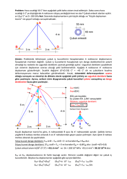
P
P
0.2 in.
0.05 in.
Prob. 4–68
B as shown. The pipe has an outer diame
wall thickness of 0.25 in. The connectio
T1 = 70°F. If the turbines’ points of
assumed to have a stiffness of k = 8011032 k
the force the pipe exerts on the turbines
and thus the pipe reach a temperature of T
•4–69.
Three bars each
made
Ödev
Noof7different materials are
connected together and placed between two walls when the
temperature is T = 12°C. Determine the force exerted
A
Soru 1. Her biri farklı malzemeden imal1 edilmiş üç çubuk birleştirilerek T1=12 Co de iki duvar
on the (rigid) supportso when the temperature becomes
arasına yerleştirilmişlerdir.
T2=18
C yeproperties
çıkartıldığında
ankastre mesnetlerde meydana
T2 Sıcaklık
material
and cross-sectional
= 18°C. The
gelecek kuvvetleri hesaplayınız.
area of each bar are given in the figure.
6 ft
B
Probs.
4–71/72
4.6
THERMAL
STRESS
272
BENDING
SteelC H A P T E R 6 Brass
Copper
Est ! 200 GPa
Ebr ! 100 GPa
Ecu ! 120 GPa
•4–81. The three
bars are made of A-36 steel and form
ast ! 12(10"6)/#C abr ! 21(10"6)/°C acu ! 17(10"6)/#C
•4–73. The pipe is made of A-36 steel an
*4–84.
Theat AM1004-T61
magnesium
all
the collars
A and B. When
the temperatu
HAPTER 6
BENDING
a pin-connected truss. If the truss is constructed when
capped
withload
a rigid
E. The
gapgas
between
is no axial
in plate
the pipe.
If hot
trave
mm2when
Aeach
cu ! 515
FUNDAMENTAL
PROBLEMS
determine
the force in
bar
the
6061-T6
alloy solid
circular
T1 = 50°F,
pipe
causes aluminum
its temperature
to rise
by ¢Tro
2 Abr ! 450 mm2
A
!
200
mm
st
Each bar has a cross-sectional area of 2 in2.
when
is at the
30° average
C. Determ
T2 = 110°F.
wherethe
x istemperature
in feet, determine
no
stress
developed
in the tube
and
rod iftht
pipe.
The
inner
diameter
is
2
in.,
the
wall
DAMENTAL PROBLEMS
4–82.
threethe
bars
areand
made
of A-36
steel and
form
F6–1. The
Express
shear
moment
functions
in terms
F6–4.to 80°
Express
the shear
moment
rises
C. Neglect
theand
thickness
of functi
the ri
aof pin-connected
truss.
If the200
truss
is constructed
when
4–74. 0 The
pipe
x, and then300
draw
the shear
and
moment
diagrams for
the
where
6 x bronze
6 1.5 mC86100
and 1.5 m
6 xhas6 an
3m
mm
mm
100 mm of joint A
determine the vertical displacement
•the
4–85.
The
magnesium
all
T
0.5
in. and
wall thickness
of
If
cantilever
shear
andaAM1004-T61
moment
diagrams
for0.2
thein.
canti
1 = 50°F,beam.
the shear and moment functions in terms
F6–4.
the shear and moment functions in terms of x,
when TExpress
capped
a rigid plate.
The gap between
throughwith
it changes
the temperature
of th
2 = 150°F. Each bar has a cross-sectional area of
aw the shear and moment diagrams for the
where
0 6 x 6 1.5 m andProb.
1.5 m4–69
6 x 6 3 m, and then draw
2 in2. edilmiş
the
6061-T6
alloy
solid
circular
9 kN
from
at A
to T
B
= aluminum
200°F
60°F atro
Soru 2. A36 çeliğinden imal
üç çubuk, mafsallı bir şekilde birleştirilerek
birTAkafes
teşkil
B =
9 kN
the
shear
and moment diagrams for the cantilever
beam.
o
when
the temperature
is at
30° The
C. Determ
axial force
itdüşey
exerts on the
walls.
pipe w
edilmiştir. Kafes T1=50 F de imal edildiğine göre, T2=150 Fo olduğunda A noktasının
temperature
to Twhich
it can be raised w
4–70.
The rod
is made
of A-36
the walls when
= 60°F.
deplasmanını hesaplayınız.
Herbir
çubuk
alanı
2 in92steel
dir.and has a diameter of
kN
yielding either in the tube or the rod. Negle
0.25 in. If the rod is 4 ft long when the springs are compressed
of the
rigid cap.
0.5 in. and the temperature of the rod is T = 40°F, determine
4 kN!m
A
the force in the rod when its temperature is T = 160°F.
x
x
4 kN!m
3m
t
5f
F6–1
1.5 4mft
3m
1.5 m
k ! 1000 lb/in.
t
5f
k ! 1000
x lb/in.
F6–4
A
1.5 m
1
8 ft
25 mm
20 mm
a
4 ft
F6–4
Section a-a
F6–2. Express
and moment Cfunctions in terms
E and moment fun
F6–5. Express the shear
B the shear D
of x, and then draw the shear
and
moment
diagrams
for
the
Prob. 4–70
of x, and then draw theProbs.
shear 4–73/74
and moment
cantilever beam.
simply
supported
beam.
3
ft
3
ft
the shear and moment functions in terms
C
F6–5. Express the shear and moment functions in terms
B
A
25 mm
aw the shear and moment diagrams for the
of x, and then draw the shear and moment diagrams for the
a
Probs.
4–81/82
simply supported
Soru 3. Şekildeki basit6 mesnetli
kirişin beam.
kayma ve moment
fonksiyonlarını x’e bağlı elde ettikten 0.2 mm
2 kip/ft
F6–1
sonra kayma ve moment diyagramlarını çiziniz.
300 mm
18 kip·ft
2 kip/ft
450 mm
A
30 kN·m
Probs. 4–84/85
4–83. The wires AB
x and AC are made of steel, and wire
x
B
AD is made
of
copper.
Before
the
150-lb
force
is
applied,
A
9 ft
AB and AC are each 60 in. long and AD is 40 in. long. If
6m
x
the temperature
F6–2 by 80°F, determine the
x is increased
9 ft
F6–5
force in each wire needed to support the load. Take
4–86. The steel bolt has a diameter of
6m 3
3
-6
E
=
29(10
)
ksi,
E
=
17(10
)
ksi,
=
8(10
)>°F,
a
st
cu
st
F6–2
through an aluminum sleeve as shown. Th
-6 the shear and moment functions in terms
Express
has a cross-sectional area of
aF6–3.
cu = 9.60(10 )>°F. Each wire
F6–5
inner diameter of 8 mm and an outer diam
2then draw the shear and moment diagrams for the
of
x,
and
0.0123 in .
F6–6.
the shearsoand
moment
fun
Soru 4. Şekildeki konsol cantilever
kirişte kesme
ve
moment
fonksiyonlarını
x’e
bağlı
elde
ettikten
The
nutExpress
at A issonra
adjusted
that
it just pre
beam.
the shear and moment functions in terms
of
x,
and
then
draw
the
shear
and
moment
the sleeve. If the assembly is originally at
kesme ve moment diyagramlarını çiziniz.
aw the shear and moment diagrams for the
simply
F6–6. Express the shear and moment functions in terms
of
then is heated to a
20°C andbeam.
T =supported
of x, and then draw the shear and moment diagrams
for the
12 kN/m
simply supported beam.
40 in.
60 in.
50 kN!m
A
3m
45!
x
3m
x
45!
A
150 lb
F6–3
6m
Prob. 4–83
F6–3
C
D
B
12 kN/m
F6–6
60 in.
20 kN!m
B
1
T2 = 100°C, determine the average norm
bolt and the sleeve. Est = 200 GPa, Eal =
-6
14(10-6
50)>°C,
kN!maal = 23(10 )>°C.
A
x
6m
F6–6
Prob. 4–86
© Copyright 2026 Paperzz