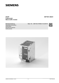
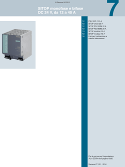
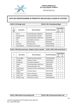
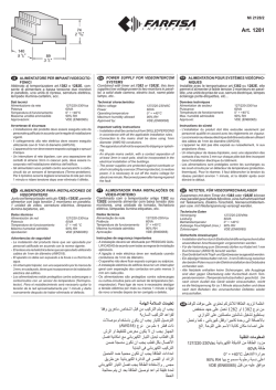
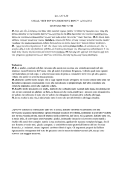
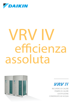
DEUTSCH
SITOP PSU200M
6EP1333-3BA10 5A
6EP1334-3BA10 10A
Betriebsanleitung (kompakt)
Operating Instructions (compact)
Notice de service (compacte)
Istruzioni operative (descrizione sintetica)
Instrucciones de servicio (resumidas)
Bild 1: Ansicht Gerät
Figure 1: View of unit
Figure 1: Vue de l'appareil
Figura 1: Vista dell'apparecchio
Figura 1: Vista del aparato
© Siemens AG 2014. All rights reserved
A5E33467757, 03.2014
FRANÇAIS
ITALIANO
ESPAÑOL
Beschreibung
Description
Description
Descrizione
Descripción
Siehe Bild 1 Ansicht Gerät (Seite 1)
See Figure 1 View of unit (Page 1)
Voir Figure 1 Vue de l'appareil (Page 1)
Vedere Figura 1 Vista dell'apparecchio
(Pagina 1)
Ver Figura 1 Vista del aparato (Página 1)
Sicherheitshinweise
Safety notes
Consignes de sécurité
Avvertenze di sicurezza
Consignas de seguridad
Die SITOP-Stromversorgungen PSU200M
sind Einbaugeräte, Schutzart IP20,
Schutzklasse I.
Primär getaktete Stromversorgung zum
Anschluss an 1-phasigen
Wechselstromnetz oder an 2 Außenleitern
von Drehstromnetzen (TN-, TT- oder ITNetz nach VDE 0100 T 300 / IEC 364-3)
mit Nennspannungen 120-230/230-500 V,
50/60 Hz; Ausgangsspannung +24 V DC,
potenzialfrei, kurzschluss- und leerlauffest.
SITOP power supplies PSU200M are builtin units, IP20 degree of protection,
protection class I.
Primary switched-mode power supplies for
connection to 1-phase AC system or to 2
line conductors of three-phase line supplies
(TN, TT or IT system in accordance with
VDE 0100 T 300 / IEC 364-3)) with rated
voltages of 120-230/230-500 V, 50/60 Hz;
+24 V DC output voltage, isolated, shortcircuit-proof and idling-proof.
Les alimentations SITOP PSU200M sont
des appareils encastrables, avec degré de
protection IP20 et de classe de protection I.
Alimentation à découpage au primaire pour
raccordement au réseau CA monophasé
ou aux 2 conducteurs de phase de réseaux
triphasés (réseau TN, TT ou IT selon VDE
0100 T 300 / IEC 364-3) avec des tensions
nominales de 120-230/230-500 V,
50/60 Hz ; tension de sortie +24 V CC,
avec séparation galvanique, protection
contre les courts-circuits et tenue à la
marche à vide.
Gli alimentatori SITOP PSU200M sono
apparecchi da incasso con grado di
protezione IP20 e classe di protezione I.
Si tratta di un alimentatore a
commutazione del primario da collegare
alla rete alternata monofase o a 2
conduttori esterni dei reti trifase (rete TN,
TT o IT secondo VDE 0100 T 300 / IEC
364-3)) con tensioni nominali 120-230/
230-500 V, 50/60 Hz, tensione di uscita
+24 V DC, a potenziale libero, a prova di
cortocircuito e resistente al funzionamento
a vuoto.
Las fuentes de alimentación SITOP
PSU200M son aparatos empotrables con
grado de protección IP20 y clase de
protección I.
Fuente de alimentación conmutada en
primario para la conexión a la red alterna
monofásica o a 2 conductores de fase de
redes trifásicas (redes TN, TT o IT según
VDE 0100 T 300 / IEC 364-3) con
tensiones nominales de 120-230/
230-500 V, 50/60 Hz; tensión de salida
+24 V DC, aislada, resistente a
cortocircuito y a marcha en vacío.
ACHTUNG
NOTICE
IMPORTANT
ATTENZIONE
ATENCIÓN
Der einwandfreie und sichere Betrieb
dieses Gerätes/Systems setzt
sachgemäßen Transport, sachgemäße
Lagerung, Aufstellung und Montage
sowie sorgfältige Bedienung und
Instandhaltung voraus.
Dieses Gerät/System darf nur unter
Beachtung der Instruktionen und
Warnhinweise der zugehörigen
Technischen Dokumentation eingerichtet
und betrieben werden.
Nur qualifiziertes Personal darf das
Gerät/System installieren und in Betrieb
setzen.
WARNUNG: KEINE SPANNUNGSANPASSUNGEN ODER DIP-SCHALTERBETÄTIGUNG IN EXPLOSIVER
ATMOSPHÄRE DURCHFÜHREN!
Appropriate transport, proper storage,
mounting, and installation, as well as
careful operation and service, are
essential for the error-free, safe and
reliable operation of the device/system.
Setup and operation of this
device/system are permitted only if the
instructions and warnings of the
corresponding documentation are
observed.
Only qualified personnel are allowed to
install the device/system and set it into
operation.
WARNING: UNDER NO
CIRCUMSTANCES MAKE ANY
VOLTAGE ADAPTATIONS OR
CHANGE DIP SWITCH SETTINGS IN
EXPLOSIVE ATMOSPHERES!
L'exploitation de cet appareil / ce
système dans les meilleures conditions
de fonctionnement et de sécurité
suppose un transport, un stockage, une
installation et un montage adéquats,
ainsi qu'une manipulation soigneuse et
un entretien rigoureux.
Cet appareil / ce système ne peut être
configuré et exploité qu'à condition de
respecter les instructions et les
avertissements figurant dans la
documentation technique
correspondante.
L'installation et la mise en service de
l'appareil / du système doit
impérativement être effectué par des
personnes qualifiées.
ATTENTION : NE PAS ADAPTER LA
TENSION NI ACTIONNER LE
COMMUTATEUR DIP EN
ATMOSPHERE EXPLOSIBLE !
Il funzionamento ineccepibile e sicuro di
questo apparecchio/sistema presuppone
un trasporto corretto, un
immagazzinaggio idoneo, una
installazione, un montaggio, un utilizzo e
una manutenzione accurati.
Questo apparecchio/sistema deve
essere installato e impiegato nel pieno
rispetto delle istruzioni e delle
avvertenze riportate nella
documentazione tecnica pertinente.
L'apparecchio/il sistema può essere
installato e messo in servizio solo da
personale qualificato.
AVVERTENZA: NON ADATTARE LA
TENSIONE E NON AZIONARE I DIP
SWITCH IN ATMOSFERA ESPLOSIVA
El funcionamiento correcto y seguro de
este aparato/sistema presupone un
transporte, un almacenamiento, una
instalación y un montaje conformes a las
prácticas de la buena ingeniería, así
como un manejo y un mantenimiento
rigurosos.
Este aparato/sistema debe ajustarse y
utilizarse únicamente teniendo en cuenta
las instrucciones y advertencias de la
documentación técnica correspondiente.
La instalación y puesta en marcha del
aparato/sistema debe encomendarse
exclusivamente a personal cualificado.
PRECAUCIÓN: ¡NO REALIZAR
ADAPTACIONES DE TENSIÓN NI
ACCIONAR INTERRUPTORES DIP EN
ATMÓSFERAS EXPLOSIVAS!
Montage
Bild 2: Montage / Demontage
Figure 2: Mounting / removal
Figure 2: Montage/démontage
Figura 2: Montaggio / smontaggio
Figura 2: Montaje/desmontaje
ENGLISH
Montage auf Normprofilschiene
DIN EN 60715-TH35-15/7,5.
Das Gerät ist so zu montieren, dass die
Eingangs- und Ausgangsklemmen unten
sind.
Unterhalb und oberhalb des Gerätes muss
mindestens ein Freiraum von je 50 mm
eingehalten werden.
Bei Installation des Gerätes in
explosionsgefährdeter Umgebung (
II
3G Ex nA nC IIC T4 Gc) ist dieses in einen
Verteilerkasten mit Schutzart IP54 oder
höher einzubauen. Dieser Verteilerkasten
muss den Anforderungen der EN 6007915:2010 entsprechen. Angewandte
Normen: EN 60079-0:2009 und
EN 60079-15:2010.
Siehe Bild 2 Montage / Demontage
(Seite 1)
Assembling
Mounting on a standard mounting rail
DIN EN 60715-TH35-15/7.5.
The device must be mounted in such a way
that the input and output terminals are at
the bottom.
A clearance of at least 50 mm must be
maintained above and below the device.
If the device is to be used in a hazardous
zone (
II 3G Ex nA nC IIC T4 Gc) it must
be installed in a distribution box with
degree of protection IP54 or higher. This
distribution box must comply with the
requirements of EN 60079-15:2010.
Applicable standards:
EN 60079-0:2009 and EN 60079-15:2010.
See Figure 2 Mounting / removal (Page 1)
Fixation
Fixation sur rail DIN symétrique
DIN EN 60715-TH35-15/7,5.
L'appareil doit être fixé de sorte que les
bornes d'entrée et les bornes de sortie se
trouvent en bas.
Un espace libre de 50 mm doit être prévu
en dessous et au-dessus de l'appareil.
Les appareils installés en atmosphères
explosibles (
II 3G Ex nA nC IIC T4 Gc)
doivent être montés dans un coffret de
distribution avec indice de protection IP54
ou supérieur. Ce coffret doit répondre aux
spécifications de la norme EN 6007915:2010. Normes applicables :
EN 60079-0:2009 et EN 60079-15:2010.
Voir Figure 2 Montage/démontage
(Page 1)
Montaggio
Montaggio su guida profilata normalizzata
DIN EN 60715-TH35-15/7,5.
L'apparecchio va montato con i morsetti
d'ingresso e quelli di uscita in basso.
Sopra e sotto l'apparecchio deve restare
uno spazio libero di almeno 50 mm.
Nel caso di installazione in aree a rischio
d'esplosione (
II 3G Ex nA nC IIC T4
Gc), l'apparecchiatura va incorporata in
una cassetta di distribuzione con grado di
protezione IP54 o superiore. Questa
cassetta di distribuzione deve essere
conforme alle specifiche della normativa
EN 60079-15:2010. Norme applicate:
EN 60079-0:2009e EN 60079-15:2010.
Vedere Figura 2 Montaggio / smontaggio
(Pagina 1)
Montaje
Fijación sobre perfil normalizado
DIN EN 60715-TH35-15/7,5.
El aparato debe montarse de modo que los
bornes de entrada y salida queden abajo.
Por encima y por debajo del aparato debe
dejarse un espacio libre de al menos
50 mm.
Si se va a instalar el aparato en una
atmósfera potencialmente explosiva (
II
3G Ex nA nC IIC T4 Gc), deberá montarse
en una caja de distribución con grado de
protección IP54 o superior. Esta caja debe
cumplir los requisitos de EN 6007915:2010. Normas aplicadas:
EN 60079-0:2009 y EN 60079-15:2010.
Véase Figura 2 Montaje/desmontaje
(Página 1)
1
Anschließen
Connecting
WARNUNG
Bild 3: Klemmendaten
Figure 3: Terminal data
Figure 3: Caractéristiques des bornes
Figura 3: Dati dei morsetti
Figura 3: Datos de los bornes
Bild 4: Eingangsklemmen
Figure 4: Input terminals
Figure 4: Bornes d'entrée
Figura 4: Morsetti d'ingresso
Figura 4: Bornes de entrada
Vor Beginn der Installations- oder
Instandhaltungsarbeiten ist der
Hauptschalter der Anlage auszuschalten
und gegen Wiedereinschalten zu
sichern. Bei Nichtbeachtung kann das
Berühren spannungsführender Teile Tod
oder schwere Körperverletzung zur
Folge haben.
Die Betätigung des Potenziometers ist
nur mittels isoliertem Schraubendreher
zulässig. Für die Installation der Geräte
sind die einschlägigen länderspezifischen Vorschriften zu beachten.
Wichtiger Hinweis: Eingangsseitig ist ein
Leitungs- oder Motorschutzschalter
vorzusehen.
Der Anschluss der Versorgungsspannung (AC 120/230/500 V) muss
gemäß IEC 60364 und EN 50178
ausgeführt werden.
Before installation or maintenance work
can begin, the system's main switch
must be switched off and measures
taken to prevent it being switched on
again. If this instruction is not observed,
touching live parts can result in death or
serious injury.
It is only permissible to use an insulated
screwdriver when actuating the
potentiometer. For installation of the
devices, the relevant country-specific
regulations must be observed.
Important note: A miniature circuit
breaker or motor circuit breaker must be
provided at the input side.
The supply voltage (AC 120/230/500 V)
must be connected in accordance with
IEC 60364 and EN 50178 .
ATTENTION
Conexión
AVVERTENZA
ADVERTENCIA
Avant de commencer les travaux
d'installation ou de maintenance, couper
l'interrupteur général de l'installation et le
condamner pour empêcher la remise
sous tension. Le non-respect de cette
consigne peut entraîner la mort ou des
blessures graves en cas de contact avec
des pièces sous tension.
Actionner le potentiomètre uniquement à
l'aide d'un tournevis isolé. L'installation
des appareils doit se faire en conformité
avec les prescriptions nationales.
Remarque importante : un disjoncteur de
ligne ou disjoncteur moteur doit être
prévu en entrée.
Le raccordement de la tension
d'alimentation (120/230/500 V CA) doit
être effectué conformément à IEC 60364
et EN 50178 .
Prima dell'inizio dei lavori di installazione
o manutenzione è necessario disinserire
l'interruttore principale dell'impianto e
assicurarlo contro la reinserzione. In
caso di mancata osservanza, il contatto
con parti sotto tensione può provocare la
morte o gravi lesioni personali.
È consentito azionare il potenziometro
solo utilizzando un cacciavite isolato. Per
l'installazione degli apparecchi occorre
osservare le normative nazionali vigenti.
Avvertenza importante: sul lato
d'ingresso si deve predisporre un
interruttore magnetotermico o un
salvamotore.
L'allacciamento della tensione di
alimentazione (AC 120/230/500 V) deve
essere eseguito in conformità alle norme
IEC 60364 ed EN 50178 .
Antes de comenzar los trabajos de
instalación o mantenimiento, se deberá
abrir el interruptor principal del
cuadro/tablero y protegerlo para evitar
su cierre. Si no se observa esta medida,
el contacto con piezas bajo tensión
puede provocar la muerte o lesiones
graves.
El potenciómetro solo deberá girarse
usando un destornillador aislado. A la
hora de instalar los aparatos, se tienen
que observar las disposiciones o
normativas específicas de cada país.
Nota importante: en el lado de entrada
debe preverse un automático
magnetotérmico o un guardamotor.
La conexión de la alimentación
(120/230/500 V AC) debe efectuarse
conforme a las normas IEC 60364 y
EN 50178 .
See Figure 3 Terminal data (Page 2)
See Figure 4 Input terminals (Page 2)
See Figure 5 Output terminals (Page 2)
See Figure 6 Signaling contact (Page 3)
Voir Figure 3 Caractéristiques des bornes
(Page 2)
Voir Figure 4 Bornes d'entrée (Page 2)
Voir Figure 5 Bornes de sortie (Page 2)
Voir Figure 6 Contact de signalisation
(Page 3)
Vedere Figura 3 Dati dei morsetti (Pagina 2)
Vedere Figura 4 Morsetti d'ingresso
(Pagina 2)
Vedere Figura 5 Morsetti di uscita (Pagina 2)
Vedere Figura 6 Contatto di segnalazione
(Pagina 3)
Ver Figura 3 Datos de los bornes
(Página 2)
Ver Figura 4 Bornes de entrada (Página 2)
Ver Figura 5 Bornes de salida (Página 2)
Ver Figura 6 Contacto de señalización
(Página 3)
Aufbau
Structure
Constitution
Struttura
Diseño
⑦
⑧
⑨
⑩
2
WARNING
Collegamento
Siehe Bild 3 Klemmendaten (Seite 2)
Siehe Bild 4 Eingangsklemmen (Seite 2)
Siehe Bild 5 Ausgangsklemmen (Seite 2)
Siehe Bild 6 Meldekontakt (Seite 3)
①
②
③
④
⑤
⑥
Bild 5: Ausgangsklemmen
Figure 5: Output terminals
Figure 5: Bornes de sortie
Figura 5: Morsetti di uscita
Figura 5: Bornes de salida
Raccordement
AC-Eingang
DC-Ausgang
Wahlschalter
Meldekontakt
Potenziometer 24 – 28,8 V
Kontrollleuchten (24 V O.K.,
OVERLOAD, SHUT DOWN)
Hutschienenentriegelung
Konvektion
Spannungsbereichsumschalter
Freiraum oberhalb/unterhalb
①
②
③
④
⑤
⑥
⑦
⑧
⑨
⑩
AC input
DC output
Selector switch
Signaling contact
Potentiometer 24 – 28.8 V
Pilot lamps (24 V O.K.,
OVERLOAD, SHUT DOWN)
Mounting rail release
Convection
Voltage range selector switch
Clearance above/below
①
②
③
④
⑤
⑥
⑦
⑧
⑨
⑩
Entrée CA
Sortie CC
Sélecteur
Contact de signalisation
Potentiomètre 24 – 28,8 V
Témoins (24 V O.K.,
OVERLOAD, SHUT DOWN)
Déverrouillage de la fixation au rail
Convection
Commutateur de plage de tension
Espace libre au-dessus / en dessous
①
②
③
④
⑤
⑥
⑦
⑧
⑨
⑩
Ingresso AC
Uscita DC
Selettore
Contatto di segnalazione
Potenziometro 24 – 28,8 V
Spie di controllo (24 V O.K.,
OVERLOAD, SHUT DOWN)
Sbloccaggio dalla guida profilata
Convezione
Commutatore del campo di tensione
Spazio libero superiore/inferiore
①
②
③
④
⑤
⑥
⑦
⑧
⑨
⑩
Entrada AC
Salida DC
Selector
Contacto de señalización
Potenciómetro 24 – 28,8 V
Pilotos de control (24 V OK,
OVERLOAD, SHUT DOWN)
Desmontaje de perfil sin herramientas
Convección
Conmutador de rango de tensión
Espacio libre arriba/abajo
Siehe Bild 7 Gesamtaufbau (Seite 3)
See Figure 7 Overall design (Page 3)
Voir Figure 7 Constitution (Page 3)
Vedere Figura 7 Struttura d'insieme (Pagina 3)
Ver Figura 7 Diseño general (Página 3)
Betriebsmodus
Operating mode
Mode de fonctionnement
Modo operativo
Modo de servicio
Parallelbetrieb und umschaltbares
Kurzschlussverhalten
Parallelschalten von zwei gleichartigen
Geräten zur Leistungserhöhung ist nur
zulässig durch Umschaltung der
Ausgangskennlinie mittels Wahlschalter A
auf ON.
Parallel operation and short-circuit
behavior that can be switched over
It is only permissible to connect two
identical devices in parallel to increase the
power rating when the output characteristic
is switched over using selector switch A to
ON.
Fonctionnement en parallèle et
comportement sur court-circuit
commutable
Le couplage en parallèle de deux appareils
de même type pour augmenter la
puissance n'est autorisé que par
commutation de la caractéristique de sortie
en plaçant le sélecteur A sur ON.
Funzionamento in parallelo e reazione al
cortocircuito commutabile
Il collegamento in parallelo di due
apparecchiature dello stesso tipo per
aumentare la potenza è unicamente
consentito con la commutazione della
caratteristica di uscita posizionando il
selettore A su ON.
Funcionamiento en paralelo y
comportamiento conmutable en caso de
cortocircuito
La conexión en paralelo de dos aparatos
del mismo tipo para aumentar la potencia
solo está permitida si se conmuta la
característica de salida colocando el
selector A en ON.
A5E33467757, 03.2014
ON
Bild 6: Meldekontakt
Figure 6: Signaling contact
Figure 6: Contact de signalisation
Figura 6: Contatto di segnalazione
Figura 6: Contacto de señalización
A
Parallelbetrieb:
Neigung der
Ausgangskennlinie
OFF Einzelbetrieb *
*
B
Speichernde
Abschaltung
Bei länger als ca.
100 ms
anstehender
Überlast erfolgt
die Abschaltung
des Gerätes. Ein
Rücksetzen erfolgt
durch
Netzversorgung
AUS für mind.
30 s
Konstantstrom *
typ. 1,2 × Nennstrom bei
Überlast/
Kurzschluss
* Auslieferzustand
Siehe Bild 8 Wahlschalter (Seite 3)
Signalisierung
LED grün
Ausgangsspannung OK
LED gelb
Überlast im Betriebsmodus
"Konstantstrom"
LED rot
speichernde Abschaltung
im Betriebsmodus "Shut
down"
A5E33467757, 03.2014
OFF Standalone
*
operation *
B
Latching
shutdown
The device is
shutdown if the
overload lasts
longer than
100 ms. Turning
the power supply
off for a minimum
of 30 s causes a
reset.
Constant current *
typ. 1.2 × rated
current for
overload/
short-circuit
* State when delivered
See Figure 8 Selector switch (Page 3)
Signaling
Green LED
Yellow LED
Red LED
Output voltage OK
Overload in the "constant
current" mode
Latching shutdown in the
"Shut down" operating
mode
ON
A
Fonctionnemen
t en parallèle :
inclinaison de
la courbe de
sortie
OFF Mode
*
individuel*
B
Coupure
mémorisée
En cas de
surcharge
présente pendant
plus de 100 ms
environ, l'appareil
est coupé. Une
remise à zéro a
lieu en désactivant
l'alimentation
réseau pendant
au moins 30 s.
Courant constant *
typ. 1,2 × courant
nominal en cas de
surcharge/
court-circuit
* Etat à la livraison
Voir Figure 8 Sélecteur (Page 3)
Signalisation
LED verte
LED jaune
LED rouge
Tension de sortie OK
Surcharge en mode de
fonctionnement "courant
constant"
Coupure mémorisée en
mode de fonctionnement
"Shut down"
ON
A
Funzionamento
in parallelo:
Inclinazione
della
caratteristica di
uscita
B
Disinserzione con
memorizzazione
Se il sovraccarico
supera i 100 ms,
l'apparecchiatura
si disinserisce. Il
ripristino avviene
azionando per
almeno 30 s il
comando OFF
dell'alimentazione
OFF Funzionamento Corrente costante *
*
singolo *
tip. 1,2 × corrente
nominale con
sovraccarico/
cortocircuito
* Stato di fornitura
ON
A
Funcionamient
o en paralelo:
Pendiente de la
característica
de salida
OFF Modo
*
autónomo*
* Ajuste de fábrica
B
Desconexión con
memoria
Si la sobrecarga
persiste más de
aprox. 100 ms, el
aparato se
desconecta. El
rearme se efectúa
si la alimentación
de red permanece
desconectada
durante al menos
30 s
Intensidad
constante *
típ.1,2 × intensidad
nominal con
sobrecarga/
cortocircuito
Vedere Figura 8 Selettore (Pagina 3)
Ver Figura 8 Selector (Página 3)
Segnalazione
LED verde
Tensione d'uscitaOK
LED giallo
Sovraccarico nel modo
operativo "corrente
costante"
LED rosso
Disinserzione con
memorizzazione nel modo
operativo "Shut down"
Señalización
LED verde
Tensión de salida OK
LED amarillo Sobrecarga en modo de
operación "Intensidad
constante"
LED rojo
Desconexión con memoria
en modo de operación
"Parada"
See Figure 9 Signaling (Page 4)
Voir Figure 9 Signalisation (Page 4)
Vedere Figura 9 Segnalazione (Pagina 4)
Ver Figura 9 Señalización (Página 4)
Siehe Bild 6 Meldekontakt (Seite 3)
See Figure 6 Signaling contact (Page 3)
Voir Figure 6 Contact de signalisation
(Page 3)
Vedere Figura 6 Contatto di segnalazione
(Pagina 3)
Ver Figura 6 Contacto de señalización
(Página 3)
Technische Daten
Technical data
Caractéristiques techniques Dati tecnici
6EP1333-3BA10
6EP1334-3BA10
24 V/5,0 A
24 V/10 A
Eingangsgrößen
Eingangsnennspannung Ue nenn:
AC 120-230/230-500 V, 50/60 Hz
Spannungsbereich:
AC 85-264/176-550 V
Siehe Bild 10
Spannungsbereichsumschalter (Seite 4)
Auslieferzustand: 230 V
Eingangsnennstrom Ie nenn bei Nennlast:
2,2/1,2 Aeff
4,4/2,4 Aeff
Eingangssicherung: intern
Empfohlener LS-Schalter Charakteristik C
(bzw.B) am 1-phasigen Wechselstromnetz
Bild 8: Wahlschalter
Figure 8: Selector switch
Figure 8: Sélecteur
Figura 8: Selettore
Figura 8: Selector
A
Parallel
operation:
Inclination of
the output
characteristic
Siehe Bild 9 Signalisierung (Seite 4)
Meldekontakt
Meldekontakt 13,14:
Ausgangsspannung O.K.
Kontaktbelastbarkeit:
AC 30 V/0,5 A DC 60 V/0,3 A DC 30 V/1 A
Bild 7: Gesamtaufbau
Figure 7: Overall design
Figure 7: Constitution
Figura 7: Struttura d'insieme
Figura 7: Diseño general
ON
6A
10 A
Für den zweiphasigen Betrieb an 2
Außenleitern eines Drehstromnetzes muss
als Schutzeinrichtung ein zweipolig
gekoppelter LS-Schalter oder ein
Motorschutzschalter vorgesehen werden.
Letzterer ist so anzuschließen, dass alle 3
Strombahnen bestromt sind.
z.B. 3RV1021-1EA10 (Einstellung 3,8 A)
oder 3RV1721-1ED10 (UL 489) bei 230 V
z.B. 3RV1021-1DA10 (Einstellung 3 A) oder
3RV1721-1DD10 (UL 489) bei 400/500 V
Signaling contact
Signaling contacts 13,14:
Output voltage OK
Contact rating:
30 V AC/0.5 A 60 V DC/0.3 A 30 V DC/1 A
6EP1333-3BA10
6EP1334-3BA10
24 V/5.0 A
24 V/10 A
Input variables
Rated input voltage Ue rated:
120-230/230-500 V AC, 50/60 Hz
Voltage range:
85-264/176-550 V AC
See Figure 10 Voltage range selector
switch (Page 4)
State when delivered: 230 V
Rated input current Ie rated at rated load:
2.2/1.2 Arms
4.4/2.4 Arms
Input fuse: Internal
Recommended miniature circuit breaker
characteristics C (or B) connected to a
1-phase AC line supply
6A
10 A
For two-phase operation connected to 2
line conductors of a three-phase line
supply, a two-pole, coupled miniature
circuit breaker or a motor circuit breaker
must be used as a protective device. The
latter must be connected so that current
flows through all 3 current paths.
e.g. 3RV1021-1EA10 (setting 3.8 A) or
3RV1721-1ED10 (UL 489) at 230 V
e.g. 3RV1021-1DA10 (setting 3 A) or
3RV1721-1DD10 (UL 489) at 400/500 V
Contact de signalisation
Contact de signalisation 13,14 :
Tension de sortie O.K.
Capacité des contacts :
30 V CA / 0,5 A 60 V CC / 0,3 A 30 V CC/1 A
6EP1333-3BA10
6EP1334-3BA10
24 V / 5,0 A
24 V / 10 A
Valeurs d'entrée
Tension d'entrée nominale Ue nom :
120-230/230-500 V CA, 50/60 Hz
Plage de tension :
85-264 / 176-550 V CA
Voir Figure 10 Commutateur de plage de
tension (Page 4)
Etat à la livraison : 230 V
Courant d'entrée nominal Ie nom dans des
conditions de charge nominale :
2,2 / 1,2 Aeff
4,4 / 2,4 Aeff
Fusible d'entrée : interne
Disjoncteur de caractéristique C (ou B)
recommandé sur le réseau CA monophasé
6A
10 A
Pour le fonctionnement biphasé avec les 2
conducteurs de phase d'un réseau
triphasé, un disjoncteur couplé bipolaire ou
un disjoncteur moteur doit être prévu en
tant que dispositif de protection. Ce dernier
doit être raccordé de manière à ce que les
3 circuits principaux soient alimentés.
Par ex. 3RV1021-1EA10 (réglage 3,8 A)
ou 3RV1721-1ED10 (UL 489) à 230 V
Par ex. 3RV1021-1DA10 (réglage 3 A) ou
3RV1721-1DD10 (UL 489) à 400/500 V
Contatto di segnalazione
Contatto di segnalazione 13,14:
Tensione di uscita O.K.
Capacità di carico del contatto:
AC 30 V/0,5 A DC 60 V/0,3 A DC 30 V/1 A
6EP1333-3BA10
6EP1334-3BA10
24 V / 5,0 A
24 V/10 A
Grandezze di ingresso
Tensione nominale di ingresso Ue nom:
AC 120-230/230-500 V, 50/60 Hz
Campo di tensione:
AC 85-264/176-550V
Vedere Figura 10 Commutatore del campo
di tensione (Pagina 4)
Stato di fornitura: 230 V
Corrente nominale di ingresso Ie nom con
carico nominale:
2,2/1,2 Aeff
4,4/2,4 Aeff
Fusibile di ingresso: interno
Caratteristica C (o B) consigliata per
l'interruttore automatico su rete alternata
monofase
6A
10 A
Per il funzionamento bifase su 2 conduttori
di linea di una rete trifase è necessario
predisporre un interruttore automatico di
protezione con collegamento bipolare
oppure un salvamotore. Quest'ultimo va
collegato in modo da alimentare tutte e 3 le
vie di corrente.
Ad es. 3RV1021-1EA10 (impostazione
3,8 A) o 3RV1721-1ED10 (UL 489) a 230 V
Ad es. 3RV1021-1DA10 (impostazione 3 A)
o 3RV1721-1DD10 (UL 489) a 400/500 V
Contacto de señalización
Contacto de señalización 13,14:
Tensión de salida OK
Capacidad de carga de los contactos:
AC 30 V/0,5 A DC 60 V/0,3 A DC 30 V/1 A
Datos técnicos
6EP1333-3BA10
6EP1334-3BA10
24 V/5,0 A
24 V/10 A
Magnitudes de entrada
Tensión nominal de entrada Ue nom:
120-230/230-500 V AC, 50/60 Hz
Rango de tensión:
85-264/176-550 V AC
Ver Figura 10 Conmutador de rango de
tensión (Página 4)
Ajuste de fábrica: 230 V
Intensidad nominal de entrada Ie nom con
carga nominal:
2,2/1,2 Aef
4,4/2,4 Aef
Fusible de entrada: interno
Se recomienda un magnetotérmico de
curva C (o B) en red alterna monofásica
6A
10 A
Para el servicio bifásico con conexión a 2
conductores de fase de una red trifásica,
debe preverse como dispositivo de
protección un magnetotérmico con dos
polos acoplado o un guardamotor. Este
último debe conectarse de forma que las 3
vías de corriente estén alimentadas.
p. ej. 3RV1021-1EA10 (ajuste 3,8 A) o
3RV1721-1ED10 (UL 489) con 230 V
p. ej. 3RV1021-1DA10 (ajuste 3 A) o
3RV1721-1DD10 (UL 489) con 400/500 V
3
Bild 9: Signalisierung
Figure 9: Signaling
Figure 9: Signalisation
Figura 9: Segnalazione
Figura 9: Señalización
Bild 10: Spannungsbereichsumschalter
Figure 10: Voltage range selector switch
Figure 10: Commutateur de plage de tension
Figura 10: Commutatore del campo di tensione
Figura 10: Conmutador de rango de tensión
Leistungsaufnahme (Wirkleistung) Volllast
(typisch)
140 W
270 W
Ausgangsgrößen
Ausgangsnennspannung Ua nenn:
24 V
24 V
Einstellbereich:
Einstellung über Potenziometer an der
Gerätevorderseite (in V)
24…28,8
24…28,8
Ausgangsnennstrom Ia nenn:
5A
10 A
Power Boost im Betrieb:
300 % Ia nenn für 25 ms
15 A
30 A
Umgebungsbedingungen
Temperatur für Betrieb:
-25 ... +70 °C;
Derating:
ab +60 °C: 3 % Ia nenn/K;
Ab Ua>24 V: 4 % [Ia]/V [Ua]
Bei Ue<100 V / <200 V: Ia max: 90 % Ia nenn
Power consumption (active power) full load
(typical)
140 W
270 W
Output variables
Rated output voltage Ua rated:
24 V
24 V
Setting range:
Set using a potentiometer at the front of
the device (in V)
24…28,8
24…28,8
Rated output current Ia rated:
5A
10 A
Power boost in operation:
300 % Ia rated for 25 ms
15 A
30 A
Ambient conditions
Temperature for operation:
-25 … +70 °C;
Derating:
from +60 °C: 3 % Ia rated/K;
from Ua>24 V: 4 % [Ia]/V [Ua]
At Ue<100 V / <200 V: Ia max: 90 % Ia rated
Verschmutzungsgrad 2
Eigenkonvektion
Schutzfunktion
Strombegrenzung bei permanenter
Überlast (>5 s),
Ansprechwert: typ 1,2 × Ia nenn,
ausgenommen Extra Power
Kennlinie der Strombegrenzung stetig
abfallend
Abmessungen
Breite × Höhe × Tiefe in mm:
70 x 125 x 125
70 x 125 x 125
Pollution degree 2
Natural convection
Protective function
Current limiting for permanent overload
(> 5 s),
response value: typ 1.2 × Iout rated,
exception Extra Power
Characteristic of current limitation
constantly dropping
Dimensions
width × height × depth in mm:
70 x 125 x 125
70 x 125 x 125
Potenza assorbita (potenza attiva) a pieno
carico (tipica)
140 W
270 W
Grandezze di uscita
Tensione nominale di uscita Ua nom:
24 V
24 V
Campo di impostazione:
Regolazione tramite potenziometro sul lato
frontale dell'apparecchio (in V)
24…28,8
24…28,8
Corrente d'uscita nominale Ia nom:
5A
10 A
Power Boost in esercizio:
300 % Ia nom per 25 ms
15 A
30 A
Condizioni ambientali
Temperatura in esercizio:
-25 ... +70 °C;
Derating:
da +60 °C: 3 % Ia nom/K;
Da Ua>24 V: 4 % [Ia]/V [Ua]
Per Ue<100 V / <200 V: Ia max: 90 % Ia nom
Consumo (potencia activa) a plena carga
(típico)
140 W
270 W
Magnitudes de salida
Tensión nominal de salida Us nom:
24 V
24 V
Rango de ajuste:
Ajuste por potenciómetro en el frente del
aparato (en V)
24…28,8
24…28,8
Intensidad nominal de salida Is nom:
5A
10 A
Aumento de potencia en servicio:
300 % Is nom para 25 ms
15 A
30 A
Condiciones ambientales
Temperatura de funcionamiento:
-25 ... +70 °C;
Reducción de potencia:
a partir de +60 °C: 3 % Is nom/K;
Desde Us>24 V: 4 % [Is]/V [Us]
Con Ue<100 V / <200 V: Is máx: 90 % Is nom
Grado di inquinamento 2
Convezione naturale
Funzione di protezione
Limitazione di corrente con sovraccarico
permanente (>5 s),
valore di intervento: tip. 1,2 × Iu nom,
escluso Extra Power
Caratteristica della limitazione di corrente
costantemente decrescente
Dimensioni
Larghezza x altezza x profondità in mm:
70 x 125 x 125
70 x 125 x 125
Grado de contaminación 2
Convección natural
Función de protección
Limitación de corriente con sobrecarga
permanente (> 5 s),
valor de reacción: típ. 1,2 × Is nom,
exceptuando Extra Power
Característica de limitación de corriente:
monótona decreciente
Dimensiones
Anchura x altura × profundidad en mm:
70 x 125 x 125
70 x 125 x 125
Zubehör
Accessories
Accessoires
Accessori
Accesorios
Entsorgungsrichtlinien
Disposal guidelines
Directives de recyclage
Direttive sullo
smaltimento
Directivas de eliminación
de residuos
Service & Support
Servicio técnico y asistencia
Funktionserweiterung durch Ergänzungsmodule Redundanzmodul, Puffermodul,
Diagnosemodul SITOP select oder
DC USV möglich
Verpackung und Packhilfsmittel sind
recyclingfähig und sollten grundsätzlich der
Wiederverwertung zugeführt werden. Das
Produkt selbst darf nicht über den
Hausmüll entsorgt werden.
Service und Support
Weiterführende Hinweise erhalten Sie über
die Homepage
www.siemens.de/sitop/manuals
http://support.automation.siemens.com
Telefon: + 49 (0) 911 895 7222
4
Puissance absorbée (puissance active),
pleine charge (typique)
140 W
270 W
Valeurs de sortie
Tension de sortie nominale Ua nom :
24 V
24 V
Plage de réglage :
Réglage par potentiomètre sur la face
avant de l'appareil (en V)
24…28,8
24…28,8
Courant de sortie nominal Ia nom :
5A
10 A
Power Boost en service :
300 % Ia nom pendant 25 ms
15 A
30 A
Conditions ambiantes
Température de fonctionnement
-25 ... +70 °C ;
Déclassement :
à partir de +60 °C : 3 % Ia nom/K ;
A partir de Ua>24 V : 4 % [Ia]/V [Ua]
Lorsque Ue<100 V / <200 V :
Ia max : 90 % Ia nom
Degré de pollution 2
Convection naturelle
Fonction de protection
Limitation de courant en cas de surcharge
permanente (> 5 s),
seuil de réponse : typ. 1,2 × Ia nom, sauf
Extra Power
Courbe de limitation de courant
décroissante
Dimensions
Largeur × hauteur × profondeur en mm :
70 x 125 x 125
70 x 125 x 125
Function expansion possible using
additional modules redundancy module,
buffer module, diagnostics module SITOP
select or DC UPS
Packaging and packaging aids can and
must always be recycled. The product itself
may not be disposed of by means of
domestic refuse.
Service and Support
You can obtain additional information
through the homepage
www.siemens.de/sitop/manuals
http://support.automation.siemens.com
telephone: + 49 (0) 911 895 7222
L'extension de fonction est possible au
moyen des modules d'extension module de
redondance, module tampon, module de
diagnostic SITOP select ou ASI CC
L'appareil et son emballage sont tous
recyclables et doivent donc être traités par
une filière de recyclage. Il est interdit de se
débarrasser de l'appareil via les déchets
domestiques.
SAV et assistance
Vous trouverez des informations
supplémentaires sur la page d'accueil
www.siemens.de/sitop/manuals
http://support.automation.siemens.com
Téléphone : + 49 (0) 911 895 7222
Ampliamento delle funzioni possibile
tramite moduli aggiuntivi: modulo di
ridondanza, modulo buffer, modulo di
diagnostica SITOP select o modulo
DC UPS
L'imballaggio e i materiali ausiliari di
imballaggio utilizzati sono riciclabili e
devono quindi essere destinati al
riciclaggio. Questo prodotto non deve
essere smaltito con i rifiuti ordinari.
Ulteriori informazioni si possono trovare
tramite la home page
www.siemens.de/sitop/manuals
http://support.automation.siemens.com
Telefono: + 49 (0) 911 895 7222
Posibilidad de ampliación funcional
mediante módulos complementarios:
módulo de redundancia, módulo de
respaldo, módulo de diagnóstico SITOP
select o SAI DC.
Todo el material usado para el embalaje es
reciclable, por lo que debería separarse
para su reutilización. El producto
propiamente dicho no deberá eliminarse a
través de la basura doméstica.
Encontrará información adicional en la
página web
www.siemens.de/sitop/manuals
http://support.automation.siemens.com
Teléfono: + 49 (0) 911 895 7222
A5E33467757, 03.2014
© Copyright 2026 Paperzz