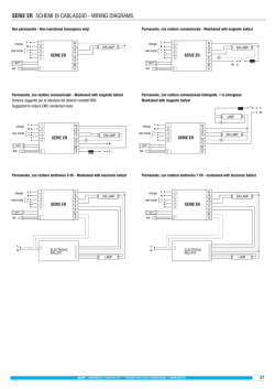
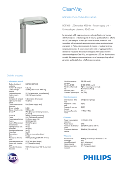
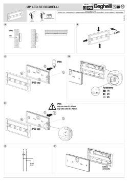
Come collegare il Fastinverter al reattore elettronico
How to connect the Fastinverter to the electronic ballast
ALIMENTATORE ELETTRONICO PER ILLUMINAZIONE DI
EMERGENZA CON POSSIBILITA' DI MODO DI RIPOSO
ELECTRONIC BALLAST FOR EMERGENCY
LIGHTING WITH POSSIBILITY OF REST MODE
made in Italy
Fig.11
Schema originale con reattore
Osram QTi 1x14W T5
Wiring Scheme with ballast
Osram QTi 1x14W T5
CARATTERISTICHE GENERALI:
- Led spia presenza rete e ricarica della batteria.
- Funzionamento con batterie al Ni-Cd.
- Dispositivo di protezione contro la scarica eccessiva della batteria.
- Prodotto conforme alle normative europee EN 61347-2-7
- Possibilità della messa nello stato di riposo tramite il comando remoto
Commander (opzionale).
- Il dispositivo di ricarica caricherà in modo normale dopo la prova par.22.3
LED
Alimentazione/Power Fastinverter
L
N
230V~
1 L
2 N
3 Lin
4 Lout
5 B
6 A
L 230V~N
FASTINVERTER T5
7
8
9
10
11
12
13
14
I
CONNESSIONE E FISSAGGIO DELL'APPARECCHIO: L'alimentatore è
previsto unicamente per essere alimentato da batterie non associate a circuiti
di ricarica a funzionamento continuo o intermittente. La scatola del Fastinverter
è stata disegnata in modo da impedire l'inversione della polarità della batteria,
effettuare la connessione come mostrato nelle figure successive..
CABLAGGIO DEL TUBO FLUORESCENTE: Nella connessione del tubo
fluorescente con il Fastinverter si raccomanda di usare cavi il più corti possibile
e ben distesi come mostrato negli schemi di collegamento.
LAMP1
NERO/BLACK
Batt.
ROSSO/RED
FASTINVERTER L
REST MODE - ENERGY TEST - SPY SYSTEM
GENERAL CHARACTERISTICS:
GB
- Indicator led for the presence of power supply and charge of battery.
- Operation with Ni-Cd batteries.
- Electronic protection device for excessive discharge of the battery.
- Device conform to rules EN 61347-2-7
- Possibility to be put in the stand-by mode by the remote control Commander
(optional)
- The racharge device will charge in the normal way after the test par.22.3
CONNECTION AND FIXING OF THE DEVICE: The plastic case of the
Fastinverter is designed to avoid the polarity inversion of the battery, connect the
battery as shown in subseguent pictrures.
CONNECTION OF THE FLUORESCENT TUBE: The device is provided only to
be supplied with batteries not associated to recharge circuits with intermittent or
continuous operation.
In the connection of the fluorescent tube to the Fastinverter the wires must be
short and straight as shown in the wiring schemes.
CARATTERISTICHE TECNICHE
BATT
TECHNICAL CHARACTERISTICS
230Vac - 50Hz
ALIMENTAZIONE/ POWER SUPPLY
L
N
MASSIMA POTENZA ASSORBITA/ MAX POWER ABSORPTION
13,5VA
TEMPERATURA DI FUNZIONAMENTO/ OPERATING TEMPERATURE
0÷40°C
2
Alimentazione/Power Ballast elettronico
SEZIONE DEL FILO PER COLLEGAM. / WIRE SECTION (mm )
TENSIONE A CIRCUITO APERTO/ VOLTAGE ON OPEN LOAD
Main Insulation
INSULATION BETWEEN POWER SUPPLY AND THE BATTERY
TEMPO DI RICARICA / CHARGING TIME
Schema originale con reattore
Osram QTP5 2x28W T5
Wiring Scheme with ballast
Osram QTP5 2x28W T5
3100VPk-Pk
Isolamento principale
ISOLAMENTO TRA ALIMENTAZIONE E BATTERIA
Fig.12
0,5÷1
12h
LED
NOTE:
1) Non mettere la batteria e il prodotto vicino a sorgenti di calore.
Don’t put the battery and the product near the Heat sources.
2) Attivare la rete 230VAC solo dopo aver completato il collegamento del prodotto ai
terminali di rete di alimentazione.
Turn on the 230Vac only after heaving connected the product to the mains terminals.
230V~
La garanzia sugli apparecchi di emergenza è di 2 anni dalla data di vendita. La garanzia decade
se il prodotto è stato manomesso o riparato da personale non autorizzato LINERGY.
The warranty on the emergency luminaire is 2 years from the sales date. The warranty voids if
the product has been mishandled or repaired by personnel not authorized by LINERGY.
-solo per i modelli Energy Test
WARNING
To connect the fastinverter T5 version to the commander in rest mode way, you
are invited to ask for the configuration of the product before buying it.
Test funzionale: viene effettuato ogni 15 giorni e consiste nella accensione della lampada per una
durata di circa 20 secondi.
-only for the Energy Test models
Test di autonomia: viene effettuato ogni 90 giorni e consiste nella completa scarica della batteria.
TEST FUNCTIONES:
- The Fastinverter T5 executes two types of Automatic test: Functional and Duration Test.
Dopo eventuali anomalie il led rosso si accenderà come spieghiamo sotto la fig.3
1 L
2 N
3 Lin
4 Lout
5 B
6 A
L 230V~N
SINCRONIZZAZIONE DEI TEST (Nell’orario stabilito ritenuto opportuno per il test)
CON COMMANDER (previa configurazione effettuate in fabbrica su richiesta):
1) Alimentare il FASTINVERTER T5, Premere il tasto OFF (il led avrà un lampeggio lento di colore
rosso) TEST DISABILITATI.
2) Premere il tasto ON (il led deve smettere di lampeggiare rosso e accendersi fisso di colore verde).
SENZA COMMANDER
1) Alimentare per la prima volta tutti i FASTINVERTER T5 presenti nell’impianto in un orario adatto
ad effettuare i test nella struttura (Alberghi, Sale convegni, scuole, etc).
2) Successivamente aprire il ponte a filo sui terminali A e B per circa 5 secondi su tutti i
FASTINVERTER T5.
NERO/BLACK
ROSSO/RED
Batt.
FASTINVERTER T5
7
8
9
10
11
12
13
14
LAMP1
ATTENZIONE:
COLLEGARE LA SCATOLA
METALLICA A TERRA
MODELLI
ENEGY TEST
LAMP2
Per ulteriori schemi di collegamento certificati
con reattori Osram, Philips, Vossloh, Helvar, ERC,
TCI, Tridonic etc, inviare una richiesta:
For any further certified wiring diagrams
with ballast Osram, Philips, Vossloh, Helvar, ERC,
TCI, Tridonic etc. send a request:
MODELLI
SPY SYSTEM
WARNING
CONNECT THE METAL CASE TO EARTH
[email protected]
+39 0735-597474
[email protected]
LINERGY SRL - via A. De Gasperi 9 - Acquaviva Picena (AP) - ITALY - tel.0735.5974 - fax 0735.597474 - www.linergy.it - [email protected] - ISTFTT5 - Ver. 3.1
Duration Test: It is performed every 90 days and consist to verify that the battery is ably to
keep the luminaire on for the nominal duration time.
After eventually fail test the red led will be on as explained under the picture n. 3
TEST SINCRONIZATION (In a suitable time to make the test)
WITH COMMANDER (prior configuration done in the factory on request)
1) Put the Main Power to the FASTINVERTER T5, Push the OFF button (Red led slow
flashing)
WITHOUT COMMANDER
1) At the first start up and in a suitable time to make the test, put the main power in all the
FASTINVERTER T5 that are in the system. (Hotels, Schools etc.)
2) Then open the jumper wire on terminal A and B for about 5 seconds on all the
FASTINVERTER T5.
MODELLI
REST MODE
LAMPADA (Resa) / LAMP (Flux Factor)
AUT.
BATTERIA
DUR.
BATTERY
CORRENTE
NOMINALE
MASSIMA
FREQUENZA
FREQUENCY
CODE
CODE
FT35N10ABRT
FT35N10ABRC
FT35N10ABR
T5: 14W (10%) 21W (12%) 24W (7%) 28W (11%) 35W (9%)
T8: 18W (7%)
1h
NiCd 6V 2,5Ah 1300mA
33 kHz
37 kHz
FT35N30ABRT
FT35N30ABRC
FT35N30ABR
T5: 14W (10%) 21W (12%) 24W (7%) 28W (11%) 35W (9%)
T8: 18W (7%)
CODE
FT80N10ABRT* FT80N10ABRC* FT80N10ABR T5: 39W (8%) 49W (9%) 54W (7%) 80W (7%)
0735-597474
Functional Test: it is performed every 15 days and consist in turning on the luminaire for a
suration of 20 seconds.
2) Push the ON button (Stop Red led slow flashing - Green led light ON)
BATT
L
N
Alimentazione/Power Ballast elettronico
CONDIZIONI DI GARANZIA / WARRANTY CONDITION
ATTENZIONE
Per collegare il FASTINVERTER T5 al Commander nella modalità REST MODE,
richiedere la configurazione del prodotto prima di acquistarlo.
FUNZIONI DI TEST:
- Il Fastinverter T5 esegue due tipi di test temporizzati: il test funzionale e il test di autonomia.
Alimentazione/Power Fastinverter
L
N
Il cassonetto barrato sull’apparecchio specifica che il prodotto deve essere consegnato ai centri
di raccolta autorizzati per un corretto smaltimento. Rivolgersi all’ufficio competente del proprio
ente locale per informazioni sulla raccolta e sui termini di legge.
The crossed out waste bin symbol indicates that the product should be taken to an authorized
waste collection centre which can dispose of it properly. For information on waste collection
centres and on current waste disposal legislation, please contact your local waste disposal
authority.
FT80N30ABRT
FT80N30ABRC
*Modello con Batteria Ni MH 6V 2,8Ah
*Model with Battery Ni MH 6V 2,8Ah
FT80N30ABR
T5: 39W (8%) 49W (8%) 54W (7%) 80W (5%)
MAX
NOMINAL
CURRENT
CON LAMPADA
WITH LAMP
SENZA LAMPADA
WITHOUT LAMP
3h
NiCd 6V 5,0Ah 1300mA
33 kHz
37 kHz
T8: 36W (6%) 58W (5%)
1h
NiCd 6V 2,5Ah 1700mA
35 kHz
37 kHz
T8: 36W (5%) 58W (5%)
3h
NiMH 6V 7,0Ah 1700mA
35 kHz
37 kHz
Le caratteristiche degli articoli e dei dati tecnici possono subire variazioni
senza preavviso ed obbligo di comunicazione per le ns.esigenze
di fabbricazione e per il miglioramento degli apparecchi.
The characteristics of the articles and the technical data contained in this
paper can be modified without notice according to our exigency.
- Schemi per Reattore Elettromagnetico
- Wiring Diagrams for Electromagnetic ballast
- Centralizzati Spy System / Centralized Spy System
Massimo 128 Plafoniere su questa linea Bus. Lunghezza massima del Cavo 500mt.
Terminare il Bus
su quest’ultima
Plafoniera.
Un tubo fluorescente ed un Reattore
One fluorescent tube and one ballast
Schema Standard
Standard Scheme
T
REATTORE/BALLAST
L
L
Plafoniere al Primo Piano
RETE/POWER 230V
s
Massimo 128 Plafoniere su questa linea Bus. Lunghezza massima del Cavo 500mt.
T
N
1
2
3
4
5
6
L
N
Lin
Lout
B
A
7
8
9
10
11
12
13
14
FASTINVERTER T5
+ -
L
A
M
P
s
Fig.4
Fig.5
Due tubi fluorescenti in serie e un reattore
Two fluorescent tubes in series and one ballast
L
Collegamento diretto delle linee Bus alla centrale Spy System
Direct connection of the Bus lines to the central Spy System
LED
Fig.1
RETE/POWER
230V~
COLLEGARE SOLTANTO IL BUS SPY SYSTEM
ONLY CONNECT SPY SYSTEM BUS
1
2
3
4
5
6
L
N
Lin
Lout
B
A
N
REATTORE/BALLAST
RETE/POWER 230V
L
L
A
M
P
Plafoniere al Piano Terra
Linea Bus 1
Rete di Alimentazione 230Vac
Linea Bus 2
Terminare il Bus
su quest’ultima
Plafoniera.
N
N
REATTORE/BALLAST
1
2
3
4
5
6
L
N
Lin
Lout
B
A
FASTINVERTER T5
+ -
7
8
9
10
11
12
13
14
L
A
M
P
s
FASTINVERTER T5
Batt.
L
A
M
P
Fig.2
s
- Modelli Energy Test con Autodiagnosi locale
- Modelli Rest Mode
Fig.7
- Energy Test with Self Test Models
- Rest Mode models
LED
Due tubi fluorescenti e due reattori
Two fluorescent tubes and two ballast
L
N
REATTORE/BALLAST
RETE/POWER
COLLEGARE SOLTANTO ILPONTE A FILO
230V~
1
2
3
4
5
6
L
N
Lin
Lout
B
A
RETE/POWER 230V
FASTINVERTER T5
L
N
Lin
Lout
B
A
FASTINVERTER T5
+ -
CONNECT ONLY THE JUMPER WIRE
Batt.
1
2
3
4
5
6
7
8
9
10
11
12
13
14
L
A
M
P
s
Fig.3
REATTORE/BALLAST
SEGNALAZIONI LED / LED SIGNALLING
SIGNIFICATO / LED MEANING
VERDE ACCESO FISSO / GREEN ON, NOT FLASHING
PRESENZA RETE, NESSUNA ANOMALIA / MAINS SUPPLY ON, NO WARNING
VERDE LAMPEGGIANTE / GREEN FLASHING
TEST IN CORSO / TEST IN PROGRESS
ROSSO LAMPEGGIANTE LENTO / RED SLOW FLASHING
TEST DISABILITATI - LAMPADA INIBITA* / TEST DISABLED - LUMINAIRE INHIBITED*
ROSSO LAMPEGGIANTE VELOCE / RED SLOW FLASHING
GUASTO BATTERIA / BATTERY FAULT
ROSSO ACCESO FISSO / RED ON, NOT FLASHING
LAMPADA GUASTA / LUMINAIRE FAULT
NOTE:
1) Non mettere la batteria e il prodotto vicino a sorgenti di calore.
Don’t put the battery and the product near the Heat sources.
L
A
M
P
s
2) Attivare la rete 230VAC solo dopo aver completato il collegamento del prodotto ai
terminali di rete di alimentazione.
Turn on the 230Vac only after heaving connected the product to the mains terminals.
Fig.6
© Copyright 2026 Paperzz