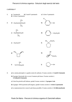
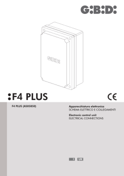
ISTRUZIONI PER USO ED INSTALLAZIONE
INSTRUCTIONS POUR L’UTILISATION ET L’INSTALLATION
OPERATING AND INSTALLATION INSTRUCTIONS
GEBRAUCHSANWEISUNGEN UND INSTALLATION
TAC10RKA
TAC10RKA/2
La ditta FERPORT S.a.s. non risponde per errati collegamenti e/o manomissioni delle centrali e tantomeno le riterrà in
garanzia.
La ditta FERPORT S.a.s. precisa di aver depositato il Mod. TAC 10RKA-RKA/2. Il medesimo sarà quindi tutelata in tutte le sue parti a
norma di legge. Nessuna parte del contenuto di questo manuale può essere riprodotta senza autorizzazione scritta della FERPORT S.a.s.
I collegamenti alla centrale devono essere eseguiti solo da personale specializzato e dopo aver attentamente letto le istruzioni sopra riportate.
N.B.: E’ richiesto l’inserimento di un interruttore onnipolare presso la centrale, con distanza di apertura minima dei contatti di 3 mm,
per lo spegnimento della stessa prima dell’apertura per manutenzione (CEI 64-8).
I
La maison FERPORT S.a.s. dégage toute responsabilité en cas de mauvaises connexions et/ou endommagement des unités. En pareil cas
la garantie n’est pas valable.
La maison FERPORT S.a.s.a déposé le Modèle TAC 10RKA-RKA/2. Toute pièce composant cette unité sera donc protégée d'après les normes en
vigueur. Aucune partie de ce manuel d’utilisation ne peut être reproduite sans l’autorisation écrite de FERPORT S.a.s.
Les connexions à l’unité ne seront effectuées que par des techniciens qualifiés et après avoir attentivement lu les instructions ci-dessus.
ATTENTION! Il est nécessaire d’équiper l’unité d’un interrupteur omnipolaire, avent une distance d’ouverture minimum des contacts de 3 mm. ce qui permet
la mise hors service de celle-ci avant l’ouverture lors des opérations l’entretien (CEI 64-8).
F
S.a.s. is not liable for damages due to incorrect connections and/or tampering of the receivers neither are such damages covered
GB byFERPORT
guarantee.
Model TAC 10RKA-RKA/2 is a registered trademark of FERPORT S.a.s. Such devices and all its parts are protected according to the existing laws.
No part of this guide may be reproduced without the prior written permission of FERPORT S.a.s.
The connections to the terminal board are to be carried out by qualified people after having read the above mentioned instructions.
NB: An omnipolar switch is required in the terminal with contacts having a minimum distance of 3 mm, in order to switch it off before servicing (CEI
64-8).
Die Firma FERPORT S.a.s. steht nicht für falsche Verbindungen und/oder Verletzungen der Steuereinheiten ein und wird sie auf jeden Fall nicht
in der Garantie einbeziehen.
Die Firma FERPORT S.a.s. gibt genau an, dass sie das Modell TAC 10RKA-RKA/2 hat patentieren lassen. Dieselbe Steuereinheit und all ihre Teile
werden deswegen auf Grund des Gesetzes geschützt. Man darf kein Teil dieses Handbuchs ohne die schriftliche Genehmigung der Firma FERPORT S.a.s.
vervielfältigen.
Die Anschlüsse an die Steuereinheit müssen nur von Fachleuten ausgeführt werden, nachdem sie die obengenannten Anweisungen aufmerksam
gelesen haben.
NB: Man braucht, einen allpoligen Schalter an die Steuereinheit mit mindestem Öffnungsabstand zwischen den Kontakten von 3 mm einzusetzen, der die
Steuereinheit vor der Instandhaltungsöffnung ausschaltet. (CEI 64-8)
D
1
Rev. 001 09/03
L1
L2
P
ITALIANO
TAC 10RKA
R1
M
TAC 10RKA/2
L1
L2
N.C.
L3
C
R1
N.A.
R2
M1
M
IMPULSO
LED L1
LED L2
LED L3
MODALITÁ
1
ON
OFF
OFF
Monostabile CH1
2
OFF
ON
OFF
Bistabile CH1
3
ON
ON
OFF
Temporizzato CH1
4
OFF
OFF
ON
Monostabile CH2
5
ON
OFF
ON
Bistabile CH2
6
OFF
ON
ON
Temporizzato CH2
2
Per la programmazione premere il
pulsante (P) seguendo le indicazioni.
Alimentazione
Assorbimento a riposo a 24 Vac
Assorbimento con relé eccitato a 24 Vac
Frequenza lavoro
Tipo ricevitore
Sensibilità
FI
Temperatura di esercizio
M Innesto Molex per centrali
produzione Ferport
M1 Morsettiera uscita CH2
NC Contatto normalmente chiuso
NA Contatto normalmente aperto
C Comune
R1 Relé canale 1
R2 Relé canale 2
P Pulsante funzioni
24 Vac/12Vcc
28,7 mA
63,5 mA
433,92 Mhz
Supereterodina
-100 dbm
455 Khz
da -20° a +60°
Una volta premuto il pulsante (P) n. volte a seconda del funzionamento voluto (monostabile/bistabile o temporizzato) e constatato
l’accensione del/i LED L1 - L2 nella giusta sequenza, premere sul trasmettitore (TAC) il canale che si desidera e constatare lo
spegnimento del LED.
A questo punto la ricevente avrà memorizzato il canale e il codice da voi dato con il radiocomando.
ESEMPIO DI FUNZIONAMENTO A TEMPO SUL CH2
Premere tre volte (6 volte x 2° CH-LED 2 e 3 ON) il pulsante, verificare l’accensione del LED 1, premere sul radiocomando il canale
che si vuole memorizzare e verificare l’accensione del LED 1 e 2.
In questo momento la scheda radio ha iniziato il conteggio del tempo.
Trascorso il tempo da noi desiderato premere nuovamente sul radiocomando il canale premuto in precedenza.
La scheda radio è pronta per il funzionamento e avrà il relé del canale temporizzato (CH2) che rimarrà eccitato per il tempo da voi
settato.
TRASMETTITORI A DIP 2K-4K
78 mm
I trasmettitori vengono forniti con 12 dip-switch. I primi 10 servono per la codifica. Il n. 11 e il n. 12 servono per assegnare il canale
al tasto CH2 (vedi illustrazione) sia sul trasmettitore a 2 che a 4 canali. La tabella qui riportata serve a configurare il CH.
CH 1
CH 2
CH 3
CH 4
ON
CH2
11
11
11
11
DIP
123456789101112
OFF
43,5 mm
Tasto configurabile attraverso i DIP 11 e 12
OFF
OFF
ON
ON
-
12
12
12
12
OFF
ON
OFF
ON
CH2
CH2
CH2
CH2
=
=
=
=
CH1
CH3
CH4
differente dagli altri 3 canali
18,5 mm
RICEVITORE A SCHEDA
I ricevitori a scheda potranno essere:
monocanali:
un relè
bicanali:
due relè
Le funzioni di questi canali saranno identiche a quelle del ricevitore da esterno.
N.B.: con questo tipo di ricevitori è necessario per una buona portata usare un’antenna esterna (AN433) dotata di cavo coassiale
RG58 (impedenza 50 ohm avente una lunghezza max di mt 10 (quella in dotazione all’antenna è di mt 5).
3
ITALIANO
CARATTERISTICHE TECNICHE
L1
L2
P
TAC 10RKA
FRANÇAISE
R1
M
TAC 10RKA/2
L1
L2
N.C.
L3
C
R1
N.A.
R2
M1
M
IMPULSE
VOYANT L1
VOYANT L2
VOYANT L3
MODALITÉ
1
ON
OFF
OFF
Monostable CH1
2
OFF
ON
OFF
Bistable CH1
3
ON
ON
OFF
Temporisé CH1
4
OFF
OFF
ON
Monostable CH2
5
ON
OFF
ON
Bistable CH2
6
OFF
ON
ON
Temporisé CH2
4
Lors de la programmation, presser le
bouton (P) comme inique.
CARACTERISTIQUES TECHNIQUES
24 Vac/12Vcc
28,7 mA
63,5 mA
433,92 Mhz
Superheterodyne
-100 dbm
455 Khz
da -20° a +60°
Aprés avoir pressé le bouton (P) selon le mode de functionnement souhalté (monostable/bistable ou temporisé) et controlé
l’activation du/des LEDS L1-L2 d’aprés la séquence appropirée, sélectionner par l’émetteur (TAC) le canal souhalté et le code que
vous avez introduits par l’intermédiaire de la radiocommande.
EXEMPLE DE FONCTIONNEMENT TEMPORISE SUR CH2
Presser trois fois (6 fois x 2° CH-LED 2 et 3 ON) le bouton, contrôler l’activation du LED 1, sélectionner pour la radiocommande le
canal qu’on souhaite mémoriser et contrôler l’activation du LED 1 et 2.
Maintenant la carte de radio a commencé le comptage du temps.
Le temps programmé écoulé, sélectioner de nouveau par la radiocommande le canal qu’on avait précédemment sélectionné.
La carte de radio est prête, à l’usage et le relais du canal sera donc temporisé (CH2): celui-ci restera excité pendant tout le temps
que vous avez programmé.
EMETTEURS POURVUS D’INTERRUPTEURS DIP 2K-4K
78 mm
Les émetteurs sont pourvus de 12 interrupteur dip. Les 10 premiers permettent le codage. Les n. 11 et n. 12 permettent d’attribuer
le canal à la touche CH2 (cf. photo ci-contre) aussi bien dans l’émetteur à 2 canaux qu’à cellui à 4 canaux. Le tableau montre
comment configurer la touche CH2.
CH 1
CH 2
CH 3
CH 4
ON
CH2
11
11
11
11
DIP
123456789101112
OFF
43,5 mm
Touche configurable à travers les DIP 11 et 12
OFF
OFF
ON
ON
-
12
12
12
12
OFF
ON
OFF
ON
CH2
CH2
CH2
CH2
=
=
=
=
CH1
CH3
CH4
diffèrent des autres 3 canaux
18,5 mm
RECEPTEUR A CARTE
Les récepteur à carte peuvent être:
monocanaux:
un relais
bicanaux:
deux relais
La fonction de ces canaux sera identique à ceux des récepteurs externe sous boîtier plastique.
N.B.: Avec types de récepteurs, pour avoir une bonne portée, il est nécessaire d’utiliser une antenne extérieure (AN433) dotée
d’une câble coaxiale RG58 (indépendance 50 OHM) d’une longueur de 5 à 10 mètres maximum.
5
FRANÇAISE
Alimentation
Absorption au repos 24 Vac
Absorption avec relais excitée 24 Vac
Fréquence de marche
Récepteur tipe
Sensibilité
FI
Température de service
M Branchement Molex pour unités de
production Ferport
M1 Boite à bornes sortie CH2
NC Contact généralement fermé
NA Contact généralement ouvert
C Broche de contact commun du râlais
R1 Relais canal 1
R2 Relais canal 2
P Bouton de fonctions
L1
L2
P
TAC 10RKA
R1
ENGLISH
M
TAC 10RKA/2
L1
L2
N.C.
L3
C
R1
N.A.
R2
M1
M
IMPULSION
LED L1
LED L2
LED L3
MODALITY
1
ON
OFF
OFF
Monostable CH1
2
OFF
ON
OFF
Bistable CH1
3
ON
ON
OFF
Timed CH1
4
OFF
OFF
ON
Monostable CH2
5
ON
OFF
ON
Bistable CH2
6
OFF
ON
ON
Timed CH2
6
Program by pressing the (P) key as
shown.
TECHNICAL SPECIFICATIONS
Power supply
Consumption quiescent at 24 Vac
Consumption with energised relays at 24 Vac
Operation frequency
Type receiver
Sensibility
FI
Operation temperature
M Molex connection for Ferport
stations
M1 Output terminal board CH2
NC Contact normally closed
NA Contact normally open
C Common contact
R1 Relay channel 1
R2 Relay channel 2
P Function key
24 Vac/12Vcc
28,7 mA
63,5 mA
433,92 Mhz
Supertherodine
-100 dbm
455 Khz
from -20° from +60°
Press the (P) key n. times according to the required operation (monostable/bistable or timed) and check that L1-L2 LEDS light in
the correct sequence, then press the required channel on the transmitter (TAC and check the LED is off.
The receiver will have stored the channel and the code set with the remote control.
Press the key (six key for 2° CH-LED 2 and 3 ON) three times check the LED lights, press th erequired channel on the remote
control and be sure that LED 1 and 2 turns on.
Now the radio board starts the time count.
At the end of the count press the channel again on the remote control.
The radio board is ready to operate, its channel relay is timed (CH2) and will be excited according to the set time.
DIP TRANSMITTER 2K-4K
78 mm
The transmitteurs are suplied with 12 dip-switches. The first 10 are for coding. Number 11 and 12 are for CH2 assign (see figure)
both on the 2 and 4 channel transmitters.
The table below is for CH2 configuration.
CH 1
CH 2
CH 3
CH 4
ON
CH2
11
11
11
11
DIP
123456789101112
OFF
43,5 mm
Key configurable via DIPs 11 and 12
OFF
OFF
ON
ON
-
12
12
12
12
OFF
ON
OFF
ON
CH2
CH2
CH2
CH2
=
=
=
=
CH1
CH3
CH4
different to the others 3 channels
18,5 mm
CARD RECEIVERS
The card receivers can be:
monochannel:
one relay
bichannel:
two relay
The functions of these channel are identical to those of the external receiver.
N.B.: With these types of receivers for good range it is necessary to use an external antenna (AN433) equipped with coaxial cable
RG58 (impedance 50 ohm) with a max length of 10 mt (the one provided with the antenna is 5 mt).
7
ENGLISH
EXAMPLE OF TIMED OPERATION ON THE CH2
L1
L2
P
TAC 10RKA
R1
M
TAC 10RKA/2
L1
L2
N.C.
L3
C
DEUTSCH
R1
N.A.
R2
M1
M
IMPULS
LED L1
LED L2
LED L3
MODALITÄT
1
ON
OFF
OFF
Monostabil CH1
2
OFF
ON
OFF
Bistabil CH1
3
ON
ON
OFF
Takmässig CH1
4
OFF
OFF
ON
Monostabil CH2
5
ON
OFF
ON
Bistabil CH2
6
OFF
ON
ON
Takmässig CH2
8
Für die Programmierung die Taste (P)
nach Anleitung drücken.
TECHNISCHE EIGENSCHAFTEN
Stromversorgung
Stromaufnahme in Ruhestellung zu 24 V Ws
Stromaufnahme mit erregtem Relais bei 24 V Ws
Arbeitsfrequenz
Schreiben Sie Empfänger
Empfindlichkeit
FI
Betriebstemperatur
M Molex Einsatz für von Ferport
produzierte Steuereinheiten
M1 Ausgangsklemmleiste CH2
NC Normalerweise geschlossener Kontakt
NA Normalerweise offener Kontakt
C Gemeinsame Erdungseinheit
R1 Relais des Kanals 1
R2 Relais des Kanals 2
P Taste der Funktionen
24 V Ws/12Vcc
28,7 mA
63,5 mA
433,92 Mhz
Superheterodyne
-100 dbm
455 Khz
von -20° zu +60°
Die Steuertaste (P), X Male je nach dem gewünschten Betrieb (monostabil / bistabil oder taktgemäss) drücken und sicherstellen,
dass die LED L1 - L2 mit der richtigen Reihenfolge leuchten, danach den für die Speicherung gewünschten Kanal auf dem
Funkensender (TAC) und sicherstellen, dass die LED sich ausschalten.
Der Empfänger hat jetzt den Code und den Kanal gespeichert, die Sie mit dem Funkensender zugeteilt haben.
BEISPIEL FÜR ZEITBETRIEB AN CH2
Drei Mal (6 Mal x 2° CH-LED 2 und 3 ON) den Knopf drücken, das Erleuchten der LED 1 überprüfen, auf der Funksteuerung den
Kanal drücken, den man speichern möchte, und das Erleuchten der LED 1 und 2 überprüfen
In diesem Moment hat der Radiodatenträger die Zeitrechnung begonnen.
Ist die von uns gewünschte Zeit vergangen, erneut auf den vorher gedrückten Kanal der Funksteuerung drücken.
Der Radiodatenträger ist bereit für den Betrieb, das Relais des zeitlich eingestellten Kanals (CH2) bleibt für die eingestellte
Zeitspanne erregt.
78 mm
Die Funksender werden mit 12 dip-switch geliefert. Die ersten 10 dienen zur Kodierung, Nr. 11 und 12 dienen dazu, der Taste CH2
den Kanal zuzuteilen (siehe Abb.), sei es auf dem Sender mit 2 als auch mit 4 Kanälen. Die hier angeführte Tabelle dient zur
Gestaltung der CH.
CH 1
CH 2
CH 3
CH 4
ON
11
11
11
11
DIP
123456789101112
OFF
43,5 mm
CH2
Taste konfigurierbar durch DIP 11 und 12
OFF
OFF
ON
ON
-
12
12
12
12
OFF
ON
OFF
ON
CH2
CH2
CH2
CH2
=
=
=
=
CH1
CH3
CH4
anders als die anderen Kanäle
18,5 mm
EMPFÄNGER MIT DATENTRÄGER
Die Empfänger mit Datenträger können sein:
Monokanal:
ein Relais
Bikanal: zwei Relais
Die Funktionen diese Kanäle sind identisch mit denen des Außenempfängers.
ANMERKUNG: mit dieser Art Empfänger ist es notwendig, eine Außenantenne anzuwenden (AN433), mit einem mindestens 10 m
langen, koaxialen Kabel RG58 (50 Ohm Impedanz). Das mitgelieferte Kabel der Antenne hat eine Länge von 5 m.
9
DEUTSCH
FUNKSENDER MIT DIP 2K-4K
NOTE
10
NOTE
11
STUDIO GRAFICO IMMAGINE (tel. 030.9913938)
Via Chienti, 10 - 20052 Monza (MI) Italy
Tel. +39.039.734095 - Fax +39.039.734951
web site: www.ferport.it - e-mail: [email protected]
12
© Copyright 2026 Paperzz