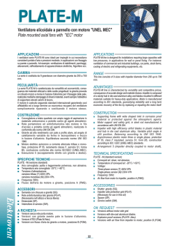
SI-BACK C
Ventilatore centrifugo pale rovesce portate basse e alte prevalenze
Centrifugal backward curved blade fan low capacities and high pressures
APPLICAZIONI
APPLICATIONS
SI-BACK C fans are designed for installations requiring modest air deliveries
with relatively high pressures, in duct mounted applications. For instance:
exhausting and filtering of industrial plants, pneumatic conveyance, transport
of solid material mixed with air, sawdust and woodchips).
I ventilatori della serie SI -BACK C sono destinati alle installazioni che
richiedono portate d’aria modeste con pressioni elevate, in istallazioni
canalizzate. Ad esempio: aspirazione e filtrazione grandi impianti industriali,
trasporto pneumatico, trasporto materiali in miscela con aria, trucioli e segatura,
con ventilatore non attraversato.
RANGE
GAMMA
This line consists of 12 sizes with impeller diameter from 350 up to 710 mm.
La gamma è composta da 7 taglie con diametro della girante da 350 a 710 mm.
ADVANTAGES
SI-BACK C line is characterized by the extreme sturdiness due to the rigid
construction in enamelled sheet metal and the thickness of the materials.
Another feature is the variety of models and versions composing the series.
PECULIARITÀ
La gamma di ventilatori SI-BACK C si caratterizza per l’estrema robustezza
dovuta alla costruzione in acciaio verniciato e agli spessori dei materiali
utilizzati. Un’altra caratteristica è la varietà di modelli e versioni che
costituiscono la gamma.
CONSTRUCTION
Volute in epoxy painted enamelled steel sheet. Fixing flanges according
to ISO 6580 / EUROVENT 1-2 standards.
High efficiency backward curved blade impeller. Balancing according
to ISO 1940.
Asynchronous three or single phase, electric motor, protection IP 55,
insulation class F, service S1, mounting type B3 or B5, construction
according to IEC/EEC (UNEL MEC).
Arrangement 4 or 5 (impeller directly coupled to motor shaft);
arrangement 1, 9, 12 (belt driven, with impeller coupled to the motor
by mean of transmission).
COSTRUZIONE
Coclea in lamiera di acciaio verniciato. Flangiatura a norme ISO
6580/EUROVENT 1-2.
Girante a pale curve rovesce ad alto rendimento. Bilanciatura a norme
ISO 1940.
Motore elettrico asincrono trifase o monofase , grado di protezione
IP 55, isolamento classe F, servizio S1, forma B3 o B5, costruzione a
norme IEC / EEC (UNEL MEC).
Esecuzioni 4 e 5 (girante direttamente accoppiata all’albero motore.
SPECIFICHE TECNICHE
TECHNICAL SPECIFICATIONS
SI-BACK C standard
Aria convogliata: anche polverosa, trasporto materiali.
Temperatura aria convogliata: -20°C / +80°C.
Tensione di alimentazione: Trifase (T) 400V – 50Hz.
Monofase (M) 230V – 50Hz
SI-BACK C standard
Conveyed air: very dusty, conveyence solid materials.
Temperature of conveyed air: -20°C / +80°C.
Voltage:
three phase version (T) 400V – 50Hz.
single phase version (M) 230V – 50Hz
ESECUZIONI
ARRANGEMENTS
SI-BACK C esecuzione 4: girante direttamente accoppiata all’albero
motore, motore posizionato su supporto (sedia)
SI -BACK C esecuzione 5: girante direttamente accoppiata all’albero
motore, motore flangiato sulla voluta del ventilatore.
SI-BACK C arrangement 4: impeller directly coupled to motor shaft,
motor placed on the motor support.
SI-BACK C arrangement 5: impeller directly coupled to motor shaft,
motor flanged on the fan volute.
ACCESSORI
ACCESSORIES
Rete di protezione lato aspirazione (IPG-SBC)
(Necessaria nell’utilizzo a bocca libera)
Rete di protezione lato mandata (OPG-SBC)
(Necessaria nell’utilizzo a bocca libera)
Giunto antivibrante aspirante (IFC-SBC)
Giunto antivibrante premente (OFC-SBC)
Controflangia aspirante (ICF-SBC).
Controflangia premente (OCF-SBC).
Portello d’ispezione (ID-SBC).
Supporti antivibranti (AM).
Foro scarico condensa (CD)
Inlet protection grid (IPG-SBC) (Necessary for use in free air)
Outlet protection grid (OPG-SBC) (Necessary for use in free air)
Inlet flexible joint (IFC-SBC)
Outlet flexible joint (OFC-SBC)
Inlet counter flange (ICF-SBC).
Outlet counter flange (OCF-SBC).
Inspection door (ID-SBC).
AV mounts (AM).
Condensation drain hole (CD)
ON REQUEST
Spark proof, explosion proof versions (SI-BACK C atex).
Stainless steel versions.
High temperature versions (150°C for direct coupling and 300°C for
belt coupling versions).
A RICHIESTA
Versione antiscintilla, antideflagrante (SI-BACK C atex).
Versioni in acciaio inox .
Versioni gas caldi (150°C per accoppiamento diretto).
SI-BACK C
Orientamenti
Discharge angles
RD 0
RD 45
RD 90
RD 135
RD 180
RD 225
RD 270
RD 315
LG 0
LG 45
LG 90
LG 135
LG 180
LG 225
LG 270
LG 315
RD
LG
158
SI-BACK C
Prestazioni
1 mm H2O= 9,8 Pa
Performances
2 POLI/POLES (3000 rpm) - T: trifase/three-phase (3Ph-400V-50 Hz)
Modello
Model
Pm
(kW)
In max
(A)
Mot
(H)
Lp
dB(A)
352/A T
352/B T
402/A T
402/B T
452/A T
452/B T
502/A T
502/B T
0,75
1,1
1,5
2,2
3
4
4
5,5
1,9
2,5
3,2
4,7
6,1
7,5
7,5
10,4
80
80
90
90
100
112
112
132
69
70
74
75
76
77
80
84
Pt (mm H2O)
Le prestazioni indicate nei diagrammi si riferiscono ad aria alla temperatura di 15°C ed all’altitudine di O mt s.l.m. , e sono state ottenute in installazioni di tipo “D” in assenza di reti e accessori .
Performance shown in the selection diagrams refer to air at 15°C temperature and 0 mt a.s.l. altitude, and they were obtained in installation type “D” with no grid nor accessories.
550
502B
525
500
502A
475
450
452B
425
400
452A
375
350
402 B
325
300
402A
275
250
352B
352A
225
200
175
150
125
100
0
500
1.000
1.500
2.000
2.500
3.000
3.500
4.000
4.500
5.000
2 POLI/POLES (3000 rpm) - T: trifase/three-phase (3Ph-400V-50 Hz)
Modello
Model
Pm
(kW)
In max
(A)
Mot
(H)
Lp
dB(A)
562/A T
562/B T
632/A T
632/B T
712/A T
712/B T
7,5
11
15
18,5
22
30
13,9
19,9
26,2
32,1
40,4
53,2
132
160
160
160
180
200
86
87
88
89
91
92
Pt (mm H2O)
Q (m3/h)
1.100
1.050
712B
1.000
950
712A
900
850
632B
800
750
632A
700
650
562B
600
550
562A
500
450
400
350
300
250
200
0
2.000
4.000
6.000
8.000
10.000
12.000
14.000
4 POLI/POLES (1500 rpm) - T: trifase/three-phase (3Ph-400V-50 Hz)
Modello
Model
Pm
(kW)
In max
(A)
Mot
(H)
Lp
dB(A)
714/A T
714/B T
804/A T
804/B T
4
5,5
7,5
9,2
8,3
11
14,6
18
112
132
132
132
71
72
74
75
Pt (mm H2O)
Q (m3/h)
325
804B
300
804A
275
714B
250
714A
225
Rpm= Numero di giri nominali del motore/ Nominal motor speed
Pm= Potenza motore/Motor power
In= Corrente assorbita/Absorbed current
Lp= il livello di pressione sonora è riferito ad una misurazione onnidirezionale
in campo libero a 1.5 m dal ventilatore con aspirazione e mandata
canalizzate.
Sound pressure level in measured in free field at 1.5 m from the fan, in
any direction, with ducted inlet and outlet.
Tolleranza sulla rumorosità - Noise tolerance: +3dB(A)
Tolleranza sulla potenza - Absorbed power tolerance: +3%
200
175
150
0
1.000
2.000
3.000
4.000
5.000
6.000
7.000
8.000
9.000
10.000
Q (m3/h)
159
SI-BACK C
Dimensioni
Esecuzione 4
Dimensions
Arrangement 4
Modello
Model
Mot
(H)
Pm Kg
(kW)
352/A T
352/B T
402/A T
402/B T
452/A T
452 B T
502/A T
502/B T
562/A T
562/B T
632/A T
632/B T
712/A T
712/B T
714/A T
714/B T
804/A T
804/B T
80
80
90
90
100
112
112
132
132
160
160
160
180
200
112
132
132
132
0,75
1,1
1,5
2,2
3
4
4
5,5
7,5
11
15
18,5
22
30
4
5,5
7,5
9,2
32
36
48
52
63
78
93
106
133
141
193
206
276
396
186
196
286
291
Ventilatore Fan
A
65
71
78
86
95
105
115
115
127
B
C
D
E
370
535 250 615
370
425
590 280 658
425
510
645 300 715
510
525
715 335 795
585
605
805 375 890
740
760
910 425 1000
760
785
1015 475 1122
860
585
1015 475 1122
650
675
1140 530 1265
675
Dimensioni in mm/Dimensions in mm
Basamento Base
H
F
G
0°
135°
180°
225°
270°
315°
I
L
M
N
O
P
Ø
215
56
355
250
355
121
14
180
45
203
225
10
238
63
375
280
375
133
17
205
55
234
260
10
265
70
400
300
400
197
23
250
30
289
324
12
297
78
450
335
450
337
89
500
375
500
23
28
250
300
300
415
30
40
40
50
289
337
337
395
324
372
372
440
12
14
381
99
560
425
560
426
108
630
475
630
426
108
630
475
630
481
122
710
530
710
197
237
237
337
337
337
357
381
197
237
28
415
50
395
440
14
33
39
23
23
460
500
250
300
70
80
30
40
434
506
289
337
488
568
324
372
17
19
237
23
300
40
337
372
12
23
12
12
Peso ventilatore in kg (completo di motore) • Weight of fan in kg (complete with motor)
B
(fig. 1)
185
205
228
255
285
320
360
405
219
241
265
292
332
366
405
448
250
275
298
325
365
400
440
485
8
8
8
8
8
8
8
12
8
8
8
10
10
10
10
10
a
b
a1
146
166
185
207
231
258
288
322
105
117
131
148
166
185
205
229
182
200
219
241
265
292
332
366
Flangia premente
(fig. 2)
Outlet flange
b1 a2 b2 n1xp n2xp
139
151
165
182
200
219
249
273
216
236
255
277
301
328
368
402
175
187
201
218
236
255
285
309
1X112
1X112
1X112
1X125
1X125
1x112
1x112
1x112
1x112
1x112
2x112
2x125
2x125
d1
n°
Ø
6
6
6
8
8
10
10
10
12
12
12
12
12
12
12
12
d2
b1
n 1p
(fig. 2)
a
a2
350
400
450
500
560
630
710
800
Flangia aspirante
(fig. 1)
Inlet flange
d
d1
d2 n° Ø
a1
n 2p
Modello
Model
Dimensioni in mm/Dimensions in mm
160
b
b2
SI-BACK SIROCCO Parti di ricambio
Spare parts
Esecuzione 4
Arrangement
7
9
8
33
1
26
6
4
2
3
30
35
Esecuzione 5
Arrangement
7
9
8
30
1
3
2
6
4
38
26
35
POS - DESCRIZIONE/DESCRIPTION
1234678917 18 19 21 22 24 -
Rete di protezione aspirante
Controflangia aspirante
Giunto antivibrante aspirante
Boccaglio di aspirazione
Girante
Rete di protezione premente
Controflangia premente
Giunto antivibrante premente
Supporto monoblocco
Puleggia
Bussola
Carter trasmissione a cinghia
Basamento
Slitte motore
Inlet protection grid
Inlet counter flange
Inlet flexible joint
Inlet nozzle
Impeller
Outlet protection grid
Outlet counter flange
Outlet flexibile joint
Single-block support
Pulley
Bush
Belt transmission guard
Base
Motor slides
25 - Trafile filettate per tensionamento
26 30 31 32 33 35 38 42 43 44 45 49 -
161
Motore elettrico
Portello d’ispezione
Cinghie trapezioidali
Ribaltina
Base di sostegno ( sedia)
Carpenteria ventilatore
Disco porta motore
Carter di protezione monoblocco
Drain plugs
Staffe di supporto carter
Supporto ribaltina
Carter coprigiunto
Threaded drawplates
for tensioning
Eletric Motor
Inspection door
V-belts
Tipper
Motor supporting base (pedestal)
Fan frame
Motor holding disc
Sigle-block protecting guard
Tappi di scarico
Carter supporting brackets
Tipper support
Joint-cover guard
SI-BACK SIROCCO Parti di ricambio
Spare parts
Esecuzione 9
Arrangement
7
43
9
8
1
6
4
2
3
35
Esecuzione 12
Arrangement
45
32
7
43
9
8
31
19
42
17
26
19
21
44
18
21
31
42
1
2
3
4
6
30
17
26
25
35
24
18
44
22
POS - DESCRIZIONE/DESCRIPTION
1234678917 18 19 21 22 24 -
Rete di protezione aspirante
Controflangia aspirante
Giunto antivibrante aspirante
Boccaglio di aspirazione
Girante
Rete di protezione premente
Controflangia premente
Giunto antivibrante premente
Supporto monoblocco
Puleggia
Bussola
Carter trasmissione a cinghia
Basamento
Slitte motore
Inlet protection grid
Inlet counter flange
Inlet flexible joint
Inlet nozzle
Impeller
Outlet protection grid
Outlet counter flange
Outlet flexibile joint
Single-block support
Pulley
Bush
Belt transmission guard
Base
Motor slides
25 - Trafile filettate per tensionamento
26 30 31 32 33 35 38 42 43 44 45 49 -
162
Motore elettrico
Portello d’ispezione
Cinghie trapezioidali
Ribaltina
Base di sostegno ( sedia)
Carpenteria ventilatore
Disco porta motore
Carter di protezione monoblocco
Drain plugs
Staffe di supporto carter
Supporto ribaltina
Carter coprigiunto
Threaded drawplates
for tensioning
Eletric Motor
Inspection door
V-belts
Tipper
Motor supporting base (pedestal)
Fan frame
Motor holding disc
Sigle-block protecting guard
Tappi di scarico
Carter supporting brackets
Tipper support
Joint-cover guard
© Copyright 2026 Paperzz